

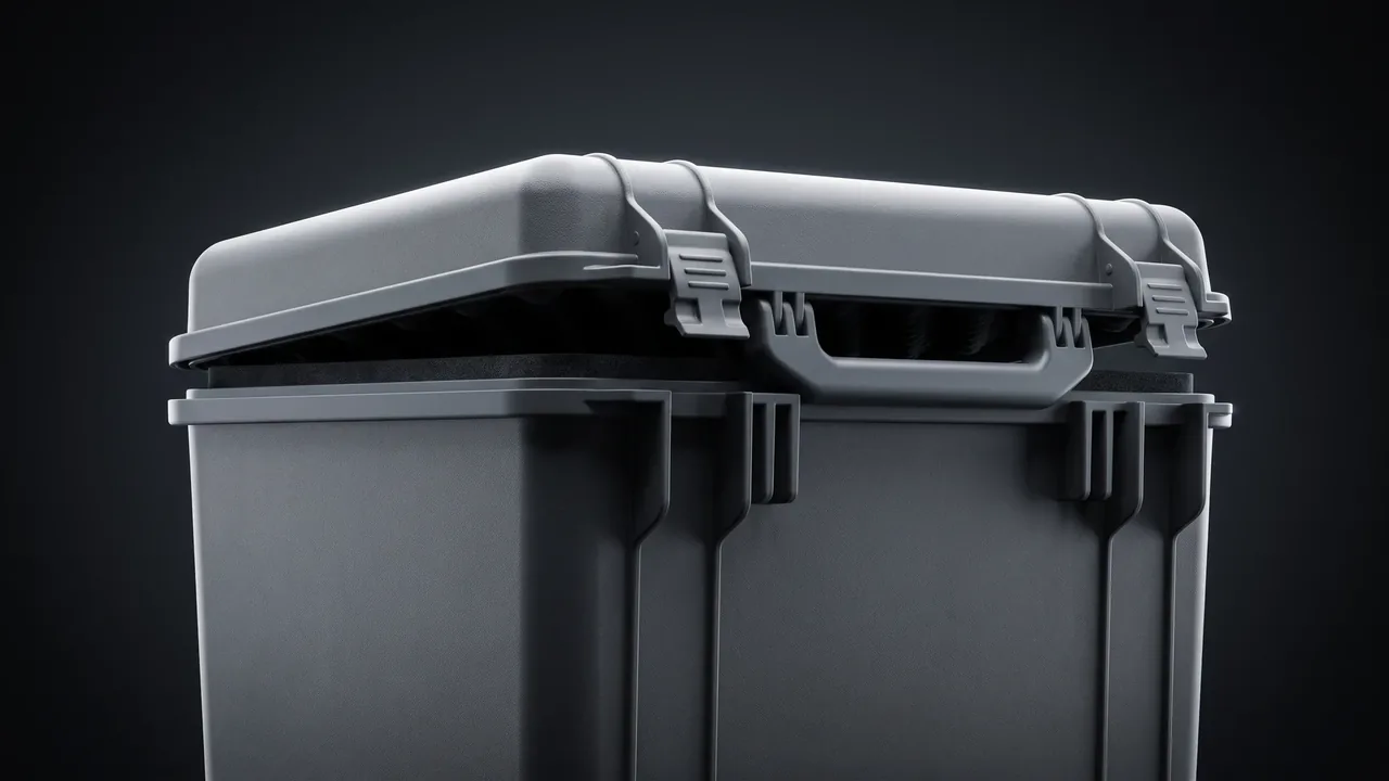
Moving equipment inside a dyeing mill is never just "load the parts on a truck." A high-temperature high-pressure dye vat is broken down for yard transfer, cross-floor relocation, or export shipment into a lid, a shell, a flange ring, a circulation pump, a seal kit and a control cabinet. The heat-setter and calender contribute a different family of parts entirely: heated rolls, rubber rolls and pneumatic pressure rolls, where a single point contact leaves a permanent mark on the roller face and a knock on the bearing seat ruins the bore. The dye liquor left in a vat is rarely clean either. Reactive dye hydrolysate is strongly alkaline, disperse dye carries dispersant residue, and the film that forms on a flange root stays invisible until a ring of red rust appears weeks later. With permanent steam haze and 80 percent relative humidity, a case left at the mill gate for half a day has already saturated its liner.
Protection does not come from making the shell harder; it comes from making the case manage three jobs at once: fully isolating residual liquor, breaking the heat path between hot components and foam, and driving contact marks on roller faces and flange faces to zero. JUNZHIJIA builds the liner for dyeing and finishing equipment around the failure mechanism of each part, splitting it into a thermal barrier layer, a chemical isolation layer and rigid locating hardware, then shipping humidity indication and documentation so incoming inspection rests on evidence rather than impression.
Table of Contents
- Steam Ageing and Compression Set of Dye Vat Flange Gaskets
- Chemical Attack of Reactive Dye Residue on Enamelled Liners
- Foam Creep and Thermal Gradient Design at 130 Degrees Celsius
- End Face Impact Protection and Rust Control for Heated and Rubber Rolls
- Maintaining Air Tightness of Pneumatic Pressure Rolls
- Condensate Retention and Drying over Long Haul Routes
- Sealing Circulation Pump Lines and Valve Ports
- Tolerance Fit and Location for Split Lid and Shell Packaging
- Fibre Dust and Humidity Exposure in Mill Workshops
- Impact Protection Boundaries for PTFE and 316L Liners
- Ballast Balance and Stacking Design for Forklift Handling
- Incoming Inspection Criteria for Residue, Ageing and Roller Marks
- Frequently Asked Questions FAQ
- Conclusion and Related Reading
Steam Ageing and Compression Set of Dye Vat Flange Gaskets
The lid and shell of a dye vat are clamped through a ring of flange gaskets. That ring rarely appears on the packing list as a critical item, yet it decides whether the vessel can be energised on arrival. The gasket spends its working life in saturated steam at 100 to 130 degrees Celsius, where rubber degrades in two ways at once. Heat breaks down the molecular chains and lowers crosslink density, so the surface turns tacky and the hardness drops. At the same time the flange holds the ring under sustained compression, squeezing the rubber into the groove until it takes a permanent set and no longer returns when the load comes off.
| Failure sign | What the site sees | What packaging can do about it |
|---|---|---|
| --- | --- | --- |
| Compression set | Bolts fully torqued and the joint still seeps | Pack the seal kit in its own box, stamp the replacement date, never let it sit under another part |
| Heat ageing and tackiness | Oily film on the sealing face, adhesion to metal | Separate dry agent and spacer pads; never bag it together with liquor-wetted metal parts |
| Groove extrusion | Lip-shaped bulge at the ring edge | Use a ring locator that blocks radial migration so the free state is never crushed |
The design rule is simple: do not drop the gasket ring into the shell as a convenient filler. The shell is a rigid body, and vibration in transit lets a small part hammer against the vessel interior. A better arrangement is a dedicated seal box with a ring locator machined to the groove diameter and an outer wrap of closed-cell foam to keep it off liquor-wetted metal. On arrival the inspector opens one box and sees immediately whether the ring is tacky, flattened or extruded, instead of digging inside the vessel. Ageing behaviour of the elastomer itself is covered under case gasket and o-ring material selection.
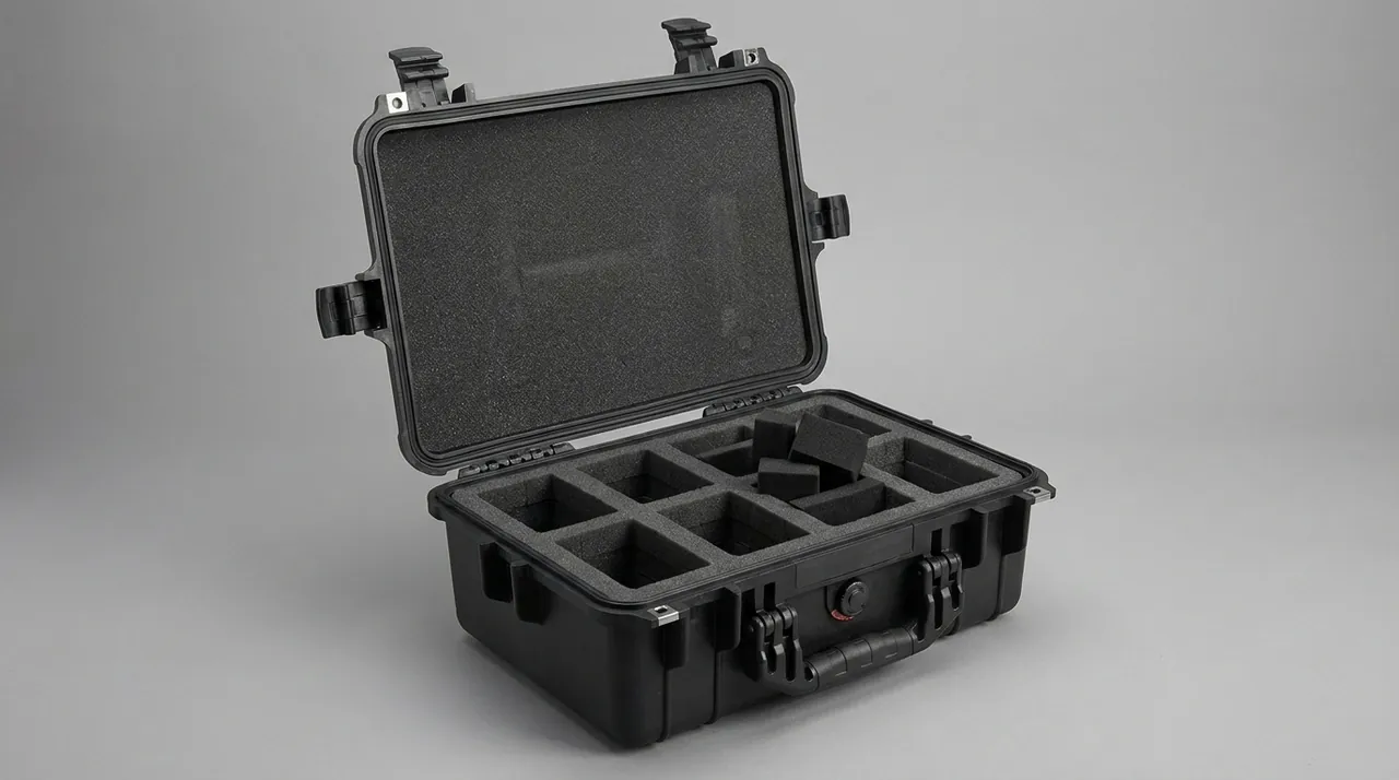
If the project requires a spare set, build a separate spare-parts box rather than mixing new rings into the vessel packaging. The spare box is small enough to ship alongside the main case and lets the site change a seal without disturbing the main liner.
Chemical Attack of Reactive Dye Residue on Enamelled Liners
Reactive dye hydrolysate attacks metal gradually but decisively. Dye vat shells commonly use 316L stainless or vitreous enamel as the corrosion barrier. One chip in the enamel glaze turns the pit bottom into bare steel, alkaline liquor collects there, and after a few weeks the rust layer spreads outward from the chip.
| Liner type | Where it usually starts | What the packaging must guarantee |
|---|---|---|
| --- | --- | --- |
| Vitreous enamel | Glaze chipping and knocked edges | Rigid edge guards, never stacked in direct contact with bare steel parts |
| PTFE lining | Scratches and pressure points that punch through | Flat continuous support, no point loading that opens a pinhole |
| 316L stainless | Pitting at welds and scratches | Passivation film plus separate bagging so residue and humidity stay sealed |
The rinse sequence matters more than the rinse volume. Flush three times with clean water until the pH reads neutral, dry, and only then close the part. Skipping any step means sealing an active corrosion reaction inside a closed box, where it runs faster. When the shell is loaded, keep the wetted inner surface facing up so residual liquor cannot pool or hang, and keep any rigid part from pressing directly on the enamel surface; a foam interlayer spreads the load. The same material-protection logic is developed further in chemical reactor parts cases.
Foam Creep and Thermal Gradient Design at 130 Degrees Celsius
A vat coming off the line can still carry 90 to 120 degrees Celsius on the lid, the flange and the pump lines. Ordinary EPE foam softens fast at that temperature: the closed-cell structure breaks down, compression set grows and rebound falls away. If the case is closed while the foam is already crushed, the box has lost its shock margin for everything that happens afterwards.
Thermal management calls for a gradient, not for more thickness. A thin dense barrier near the part blocks radiant heat, a medium-density layer absorbs the mechanical energy, and a static air gap in between does the insulating work. The outer layer takes the stacking load. The three zones have different jobs, and none of their densities substitutes for another.
| Layer | Load or heat it faces | Density direction | Consequence of failure |
|---|---|---|---|
| --- | --- | --- | --- |
| Inner thermal barrier | Part temperature 90 to 120 degrees Celsius | Dense, low conductivity | Direct contact scorches the foam and leaves a heat mark |
| Middle cushion | Vibration and impact energy | Medium density, compressible | Under-compression passes energy into the rigid divider |
| Outer load layer | Stacking mass and forklift handling | High density, high crush resistance | Once crushed, the whole cavity loses its cushion |
Thickness should be derived from the permitted acceleration and the allowable foam compression rather than from a habit of adding more foam. For a 130-degree-class heat source, allow at least 25 to 30 mm of combined thermal layer, and force the part down to below 45 degrees Celsius before the case is closed.
End Face Impact Protection and Rust Control for Heated and Rubber Rolls
Heated rolls on a heat-setter or calender are the most touch-sensitive parts in the whole machine. The working face is usually hard-chromed or mirror polished, so any point contact leaves a mark that never comes out. At temperature the surface also reacts with air to form oxide scale, and once that scale is fingerprinted or contaminated with oil, corrosion starts at the print. Rubber rolls are worse in a different way: the edges chip away after a single impact.
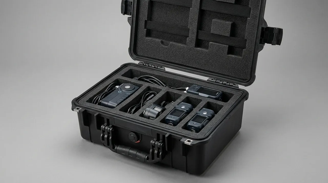
End face protection needs three separate actions, and missing any one of them defeats the others. First, isolate the journal: fit a rigid end cap over every shaft end and leave 3 to 5 mm of clearance so vibration cannot drive the shaft into the cap. Second, redirect the load: fit rigid corner guards or impact posts on both sides of the roll so a fork tine or a dropped dunnage block strikes the guard rather than the roller face. Third, pack separately: wrap rubber rolls in their own dust film and foam and never stack them in the same layer as metal rolls, because a metal edge will press into the rubber.
Rust control needs the right chemistry. Hard chrome does not tolerate alkaline rust inhibitors, so use a neutral or mildly alkaline vapour corrosion inhibitor and place a non-woven barrier film between the roller face and the foam so that cushioning-agent bleed cannot set up electrochemical attack on a damp surface.
Maintaining Air Tightness of Pneumatic Pressure Rolls
A pneumatic pressure roll uses compressed air to drive a cylinder and apply line pressure to the fabric. The whole value of that roll depends on air tightness: lose 0.2 bar and the nip force drops noticeably, and the sheen and thickness uniformity of the finished fabric suffer immediately.
Air tightness fails in three predictable places. At the piston rod seal, a rod left fully retracted during transport can be pushed against the cylinder cap by residual pressure and held a few microns open, leaking slowly. At quick couplings, vibration loosens the fitting and turns the port into a free jet that blows straight at the dry agent. At solenoid valves and pneumatic controllers, damp coils become slow and hesitant.
Treat the air circuit as its own small subsystem inside the case. Blank off the cylinder ports and mark the case "vent to 0 bar before transport". Bag the lines separately, cap both ends and include dry agent. Give the control components an anti-static liner pocket so they never sit directly against bare foam. Pressure-bearing parts should be leak tested with a hold test before the air line is connected at site, and that data only counts if the transport orientation marking on the case was actually respected.
Condensate Retention and Drying over Long Haul Routes
Dyeing and finishing halls are permanently humid, and parts coming off the line often carry a film of water. The temperature swing begins the moment the case is closed: the sun drives the interior to 50 degrees Celsius in the afternoon and it falls to 10 degrees at night, and atmospheric moisture condenses onto foam and metal as a fine dew. Repeat that cycle daily on a 30 to 45 day sea voyage and any untreated steel part will bloom with rust while paper labels go soft and mouldy.
Three drying measures have to be used together, and none of them replaces the others.
| Measure | What it does | Configuration note |
|---|---|---|
| --- | --- | --- |
| Desiccant | Adsorbs water vapour inside the case | Size the charge from cavity volume and transit time, and confirm it is not spent before packing |
| Humidity indicator card | Lets the receiver judge at a glance whether humidity was exceeded | Place it where drying is hardest: the floor, recessed cavities, inside coiled hose |
| Structural ventilation | Gives the desiccant a convective path | Cut vent channels in the liner instead of closing dead volumes |
For long sea routes, add a rain cover outside the case or select a composite panel with a moisture barrier. Fix the desiccant to structural parts so it cannot migrate into one corner and leave the rest of the cavity unprotected. On arrival, read the card first and only then decide whether the whole case needs drying; reversing that order leaves you drying an already dry interior while the corrosion source stays. Salt spray testing helps rank surface treatment options, but salt spray results compare schemes and cannot be converted directly into field service life.
Sealing Circulation Pump Lines and Valve Ports
The circulation pump and its pipework are the wettest hiding places on a dye vat. The pump outlet, the butterfly valve body, the inside of every bend and each tee branch are dead legs where residual liquor collects. That liquid sloshes inside the case, wicks through the liner and pools under metal parts, so rust begins where nobody can see it.
Block the ports in bands by nominal diameter. For DN25 and below, push a soft labelled plug into the port and write "drained" or "contains residue" so the site cannot reconnect the wrong line. For DN32 to DN80, wrap the end with shrink film or stretch film and add a scratch-resistant foam sleeve so the seal is not punctured by a case edge. For main return lines above DN100, assemble them in place and bolt a blind flange on, so a large free end never forms inside the case.
Pack the pump itself as a machined component: align the shaft and coupling and lock them with a clamp, and make sure the pump casing never carries the lifting load of the case. Set every valve stem at half open, which avoids both impact and pressure lock, and note the removal and reset steps in the case documentation. Related pump protection scenarios are covered under diaphragm pump cases.
One detail is easy to miss: the flange between pump and pipework is the joint most likely to be bent in transit. With no pipe support, vibration makes the line work repeatedly at the flange while the pump weighs hundreds of kilograms, and the flange eventually pulls out of alignment and leaks the moment power is applied. Support every line longer than 1.2 m with a pipe clamp, using a soft sacrificial pad rather than metal so no hard mark is left behind.
Tolerance Fit and Location for Split Lid and Shell Packaging
Dye vats are commonly shipped as a separate lid and shell because that is the most space-efficient arrangement, but it creates a tolerance problem. The lid flange has to be re-aligned to the shell flange on site, and if transport produced any knock or slight distortion the bolt holes no longer line up. Forcing the joint together damages the flange sealing face, and the leak that follows is attributed to the gasket rather than to the packaging.
Split-part packaging solves three things. Provide alignment marks on both flange faces so the site can reassemble from the marks instead of trial fitting and abrading the sealing face. Fit removable guide rings over the locating spigots so the two halves cannot strike each other and deform the pilot edge during transit. Add non-metallic locating blocks that limit relative sliding without ever allowing hard contact.
Inside the case, support the shell on three hard points with a circumferential restraint, so the weight lands on rigid supports instead of a broad area of foam that would creep under long compression. Build the locating blocks from a material that cannot scratch enamel or coating. Valves, instruments and terminal boxes go into their own compartments rather than sharing a foam layer with the vessel cavity, a principle shared with heat treatment equipment cases.
Splitting the vessel also pays an unexpected dividend. With lid and shell separate, moisture-absorbent film or a humidity-regulating sheet can be placed inside the cavity, actively holding the internal atmosphere in the non-corrosive range. A one-piece vessel is a sealed dead volume where humidity can only be absorbed; a split vessel gives the site one ventilation opportunity before assembly. Adding a setting template between the two halves also preserves the machined fit of the vat mouth without repeated trial assembly.
Fibre Dust and Humidity Exposure in Mill Workshops
Short fibre lint hangs permanently in the air of spinning, chemical fibre and non-woven halls. A protective case left open while waiting to be packed collects that lint onto the liner surfaces, where it combines with moisture into a damp mat that blocks inspection and holds humidity against metal parts.
Three responses apply. Clean before loading: vacuum the cavity and wipe it with a non-woven cloth, never close a case that has been loaded in humid workshop air. Compartmentise: separate lint-prone areas such as fabric guide rolls and heating tubes from clean items such as terminal boxes with a solid divider rather than a shared foam layer. Ventilate structurally: cut vent channels in the liner so the desiccant has a convective path and moisture cannot settle in a dead volume.
Lint environments differ between non-woven and spinning equipment, so vent geometry and filter media follow different choices; these are discussed under non-woven line cases and spinning frame cases. Housings for these applications normally use an antistatic polymer formulation so lint is not electrostatically attracted and cleaning stays practical.
The wear from pushing a case across the workshop floor belongs in the same calculation. Iron swarf, sand grains and chemical crystal are tracked in from the floor and repeatedly rolled under the feet as the case is moved, so the lower edge of the base and side walls scratch quickly. The scratches do not change the protection rating, but they become the entry point for water and damp, and cases that have crossed a long sea route do occasionally show water tracking from a scratch line. Either fit replaceable wear plates on the feet or raise the case at least 30 mm off the floor so the travel surface never touches hard ground.
Impact Protection Boundaries for PTFE and 316L Liners
The characteristic failure of a PTFE-lined dye vat in transit is puncture. PTFE resists corrosion but not point load: a single small corner pressed into the lining can create an invisible pinhole that only shows as a leak after the vessel is back in production.
For a 316L liner the concern is scoring instead. Once a scratch exposes fresh metal, pitting develops quickly when residual liquor and humidity are both present.
| Liner | How the load is carried | Forbidden | Mandatory |
|---|---|---|---|
| --- | --- | --- | --- |
| PTFE lining | Distributed multi-point support | Single-point concentrated load, hard parts stacked directly on top | Flat support plate plus a continuous soft pad |
| 316L liner | Rigid support points take the weight | Direct bare steel contact, dragging during handling | Passivation film plus a non-woven isolation layer |
One more boundary deserves attention: the joint between the liner and the vessel wall is a stress concentration zone. Foam should be cut so that the region below this joint is a softer transition, which prevents long-term compression from concentrating stress onto the liner edge. General acceptance criteria for pressure-retaining parts are discussed under pressure vessel component cases.
Ballast Balance and Stacking Design for Forklift Handling
Dyeing machine parts have high density. Enamelled shells, heated rolls and circulation pumps are heavy for their footprint, so sizing a case purely from outside dimensions often produces the worst outcome: poor space utilisation combined with a case that is itself too heavy for the forklift. Goods fill barely half the volume while dead weight consumes the rated capacity.
Three points govern ballast design. Load low: put pumps, valves and other small heavy items into the bottom foam compartment and place light lid panels on top, so the centre of gravity stays in the lower third. Provide forklift access: reserve side fork pockets and fit load-bearing lifting slings underneath, anchored to the case's structural members rather than to foam. Mark the stacking limit: derive the maximum number of tiers from the allowable compressive load of the heaviest item, heated rolls and pump casings, and print that number on the outside of the case.
Stacking calculations and tier limits are covered under stacking load testing for cases. Transport mode also drives the protection grade, because the damp heat of a sea voyage and the impact levels of air freight are different problems. Test conditions belong in the purchase specification rather than in a copied template.
Incoming Inspection Criteria for Residue, Ageing and Roller Marks
Incoming inspection is not finished when the box turns up undamaged. Dye vat parts have a definite inspection sequence, and following the wrong order destroys the evidence.

Step one is the closed-case pass. Examine the exterior for damage and water ingress, read the humidity indicator and photograph the reading. If the card has exceeded its limit the interior has spent time in high humidity, so dry the whole case before opening it.
Step two follows a fixed unpacking order. Check the seal and closure condition first, remove the desiccant next, and only then lift out the liner compartments. Photograph each layer as it comes out; pulling everything out at once scatters the liner and makes it impossible to reconstruct where parts sat relative to each other at impact.
Step three judges each part against criteria.
| Item | Accept criterion | Action if rejected |
|---|---|---|
| --- | --- | --- |
| Vat interior residue | No visible liquid film, pH paper reads neutral | Record and photograph, notify the shipper, never rinse and stay silent |
| Flange gasket | No tackiness, no flattening, no extruded lip, specification marking legible | Replace the full ring and record the batch |
| Roller face | No indentation or rust spot on the mirror surface, no chipping on rubber | Photograph with position marked and assess whether line pressure is affected |
| Pump line ports | Blanks present, lines dry with no residue | Re-seal and re-inspect |
| Terminal box | Dry, no condensation, no mould | Insulation test before energising |
Any nonconformance must be recorded on site and photographed, then compared against the packing record to determine whether the damage occurred in transit or during packing, and notified to the shipper rather than absorbed locally. The packing list, gasket specification sheet, liner configuration table and transport test records should travel with the case so the destination can provide a compliance basis at customs and during incoming inspection. Sampling limits for that inspection are set out under custom case acceptance standards.
Frequently Asked Questions FAQ
Q: What special handling does a dye vat flange gasket need during packing?
A: The gasket ring should not simply be dropped into the vessel shell. Vibration in transit makes a small part hammer against the metal interior, and residual heat accelerates rubber ageing long before the vessel is ever energised. Pack it into a dedicated seal box, add a ring locator machined to the groove diameter so radial migration is constrained, wrap the outside with closed-cell foam to keep it away from liquor-wetted metal, and include a small sachet of desiccant in the same box. Mark the box with the original specification, production date and recommended replacement interval. This lets the inspector open one box and judge at once whether the ring is tacky, flattened or extruded at the groove edge, instead of digging inside the vessel with a torch. Where the gasket is supplied as a continuous coil rather than a cut ring, support it on a wide flat core so it does not take a set from its own weight, and note in the case file that it must be cut and re-joined on site. Long-term ageing behaviour of the elastomer itself is covered under case gasket and o-ring material selection.
Q: Can a dye vat still at 130 degrees Celsius be packed straight away?
A: No. Force it below 45 degrees Celsius before closing the case. Ordinary EPE foam softens rapidly at surface temperatures of 90 to 120 degrees Celsius: the closed-cell structure is damaged, compression set increases and rebound drops sharply. Closing the case at that point means the foam is already crushed, so the box has no shock margin left for the vibration still to come. The correct sequence is to disassemble the vessel, rinse out the liquor, dry every part, and only then apply the thermal packaging in layers: a thin dense barrier against radiant heat, a medium-density cushion for mechanical energy, a static air gap between them, and a high-density outer layer carrying the stacking load. For a 130-degree-class heat source, allow at least 25 to 30 mm of combined thermal layer before closure, and verify the result with a contact thermometer rather than trusting the cooling curve of the shell wall, since the pump lines and the flange lag well behind the main body and can still be hot hours after the vessel feels cold to the hand.
Q: How should reactive dye residue be treated to pass incoming inspection?
A: Three steps in strict order. Rinse with clean water until the pH paper reads neutral, dry the part thoroughly with forced air, and only then seal it. Sealing alkaline or reductive residue into a closed case lets the reaction continue inside the box, and metal pitting and fabric colour return occur at the same time. After rinsing, always inspect the enamel glaze for chips, because the bottom of a glaze chip is bare steel where liquor collects for weeks and rust then spreads along the chip edge in a ring pattern that is easy to miss on a curved surface. When loading, orient the shell so the wetted inner face points upward to prevent pooling, and never let a rigid part rest directly on the glazed surface; a foam interlayer spreads the load without scratching. Where the vessel has a PTFE lining rather than enamel, check for pinholes instead, since a puncture is invisible until the vessel is refilled and heated; a bright light held behind the lining makes them easy to spot before assembly.
Q: How much desiccant should a case carry for a 40 day sea voyage?
A: Size it from cavity volume, transit duration and expected temperature and humidity conditions rather than from a fixed count per case. The governing rule is that the adsorption capacity must comfortably exceed the theoretical condensation load of the whole route, typically with a two to three times margin. Three measures work together: desiccant adsorbs, the humidity indicator card is placed where drying is hardest so the receiver can judge it, and structural vent channels give the desiccant a convective path instead of letting moisture sit in a dead volume. Do not close the liner into a fully sealed cavity, because trapped air simply becomes a saturated reservoir that condenses on the first cold night. Adding an external rain cover or selecting a composite panel with a moisture barrier markedly reduces arrival-side humidity as well. On arrival, read the card before opening, and photograph the reading for the acceptance record. Where the route crosses two climate zones, a second card placed near the upper corner gives a second data point, because condensation often starts high in the cavity where the metal is coldest. Stacking and humidity rules of this kind are covered under warehouse stacking and moisture cases.
Q: A heated roller arrives with a pressure mark. How is liability established?
A: Look first at the position and shape of the mark, then compare against the packing photographs. A regular line-shaped indentation across the mid-span usually means an upper part was stacked directly on the roller face, which is a packing fault. An indentation near the end face combined with displaced guarding points more towards transport vibration layered on top of stacking. Either way the judgement depends on packing records: photograph every layer, and record the orientation and support points for each part. End faces need rigid caps with 3 to 5 mm axial clearance, plus corner guards or impact posts on both sides so fork tines and dropped dunnage hit the guard first. On a rubber roll, compare the mark against a durometer reading as well, because a flattened or hardened spot changes the nip force and cannot be corrected by cleaning. Without a full set of packing records the argument cannot be settled on appearance alone, so agree the photograph protocol before the first case is packed rather than after the first dispute.
Q: Should pneumatic pressure rolls be leak tested after transport?
A: Yes, and the test belongs before the air line is connected. The piston rod seal can be pushed against the cylinder cap by residual pressure when the rod is fully retracted, opening a gap that leaks slowly. Quick couplings loosen under vibration and turn the port into a jet that dries the desiccant prematurely. Coil-controlled valves become hesitant once damp, so a roll that performs correctly on site may still carry a fault from the voyage. Blank off the cylinder ports and mark the case "vent to 0 bar before transport", bag the lines with both ends capped plus dry agent, and put the control components in an anti-static liner pocket so they never sit against bare foam. On arrival, run a hold test at rated pressure and log the decay curve rather than a single endpoint value, since a slow leak passes a quick check and fails a long one. The result is only meaningful if the transport orientation marking on the case was followed exactly.
Q: What information does JUNZHIJIA need from a client to customise dyeing equipment cases?
A: At least six items. First the equipment list with maximum dimensions, weight and centre of gravity for each part. Second the working temperature and the residual medium, including dye type, pH and whether reducing agents are present. Third the flange gasket specifications and quantities. Fourth whether the shell ships split, and whether the destination site has lifting equipment for assembly. Fifth the intended transport mode and route, including sea legs and the number of transfers. Sixth the destination requirements for packing marks and case documentation. JUNZHIJIA then fixes the compartment structure, foam layering, thermal thickness, sealing class and latch configuration, and runs tooling, sample verification and volume delivery under one customisation plan. Providing a photo of the actual vessel at the packing point, rather than a catalogue drawing, removes most of the guesswork from the liner layout and shortens the sample approval cycle considerably. It also helps to flag which components are supplied as customer spares, since those are usually packed separately and should not consume the main cavity volume.
Q: Why can the liner of a dyeing equipment case not use one foam type throughout?
A: A single foam cannot satisfy thermal barrier, cushioning and load bearing at once. The zone facing 90 to 120 degrees Celsius needs a dense, low conductivity barrier. The zone facing vibration needs a compressible cushion with reliable rebound. The zone carrying the weight of the stacked case above needs a high-density crush-resistant structure. Using one material everywhere leads to a predictable failure: insufficient thermal performance leaves heat marks and crushed foam, while insufficient structural capacity lets the upper tier collapse into the cavity. Workshops heavy with fibre lint also call for an antistatic formulation, otherwise accumulated dust combined with damp becomes almost impossible to clean out. Where chemical isolation matters, a non-absorbent closed-cell facing sheet between foam and metal keeps any bleed from the cushioning agent out of the residue, protecting both the part and the case.
Conclusion and Related Reading
Transport protection for dyeing equipment works only when residual liquor, residual heat and roller contact risk are handled together. JUNZHIJIA customises compartment liners per failure mode and supports tooling, OEM/ODM and case documentation from Kexin New Materials (Guangdong) Co., Ltd.
Related Reading