

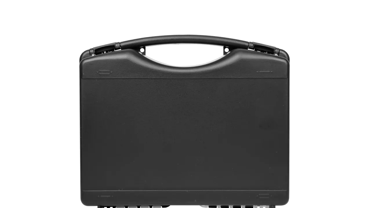
A titanium dioxide (TiO2) plant rarely gets more than 24 to 72 hours of shutdown, so a feed nozzle, an agitator shaft or a dispersion disc that arrives bent, chipped or rusted at the sealing face can push the restart back by weeks. These are not ordinary machine components: when they come off the line they still carry residual sulfuric acid, chloride ions and a very fine white pigment powder with exceptional hiding power. Those three factors turn transport protection into a combined problem of corrosion control, contamination isolation and dimensional stability.
The JUNZHIJIA position is straightforward: a case for TiO2 line components must be engineered in four stages — neutralise the residual medium, isolate the cleanliness, lock the geometry, and keep the journey traceable — so the corrosion source is contained inside the case and the deformation risk is locked into the liner. The sections below work through each process stage, the failure modes of the parts involved, and the case parameters that can be written directly into a procurement specification.
Table of Contents
- The Dual Challenge of Corrosion and Contamination on a TiO2 Line
- Oxidation Reactors: Protecting Feed Nozzles and Cooling Components
- Surface Treatment Coating Tanks: Packing Agitator Shafts and Dosing Parts
- Sand Mills and Bead Mills: Securing Dispersion Discs and Chamber Parts
- Gas-Powder Separation and Conveying Parts: Dust Ingress and Static Control
- Sulphate Route Corrosion: Concentrated Acid and Chloride Attack
- Material Selection: PP, ABS, PC and Stainless Steel Frames
- Sealing Ratings: IP65/IP67 under IEC 60529 and GB/T 4208
- Cushioning Liners: Layered EPE, EVA, PE and IXPE Combinations
- Compartments, Latches and Hinges: A Traceable Internal Layout
- Pressure Equalisation Valves and Internal Temperature-Humidity Control
- Stacking Load and Transport Testing: ISTA, GB/T 4857 and ASTM D4169
- Acceptance Criteria and Incoming Inspection Checklist
- Frequently Asked Questions FAQ
- Conclusion and Related Reading
The Dual Challenge of Corrosion and Contamination on a TiO2 Line
The sulphate route dominates TiO2 production, from ilmenite digestion through hydrolysis, salt treatment, calcination, grinding, surface treatment and sand milling to gas-powder separation and packing. The chloride route is shorter but concentrates chlorine gas and titanium tetrachloride. Both share one feature: wherever a part meets slurry, acid mist or high-temperature steam, its surface condition is part of product quality, and a micron-scale scratch starts the next pitting cycle.
Transport adds four threats. Residual medium corrosion: a dismantled part may still hold 20 to 60 percent sulfuric acid or chloride rinse water, creating a wet acidic micro-environment inside a sealed case for hundreds of hours. Powder contamination: TiO2 dust is fine and strongly hiding, so once it reaches an electrical component or sealing face, routine wiping will not restore it. Structural deformation: 0.1 mm of nozzle bore deviation or 0.2 mm per metre of shaft bow shifts flow distribution and coating uniformity. Cleanliness failure: a surface treatment part travelling with carbon steel brings iron ions into the coating tank as rust contamination.
That table is the dividing line for case design: parts from one line cannot share a single case model. JUNZHIJIA starts every TiO2 programme by tagging the parts list against residual medium, geometric sensitivity and cleanliness level, since only parts with the same tag may share one liner design.
| Process stage | Typical parts | Main threat | Protection focus |
|---|---|---|---|
| --- | --- | --- | --- |
| Digestion / hydrolysis | Digester lining, agitator impeller | Concentrated acid, heat | Acid-resistant liner, venting |
| Oxidation reaction | Feed nozzle, cooling coil, distributor | Mixed acid mist, Cl-, deformation | Single-part locking, anti-deformation cradle |
| Surface treatment | Agitator shaft, dosing line, pH probe seat | Dilute acid, scale build-up | Compartment isolation, clean liner |
| Sand milling | Dispersion disc, chamber liner, seal | Media impact, dynamic balance | Heavy cushioning, axial restraint |
Oxidation Reactors: Protecting Feed Nozzles and Cooling Components
The oxidation reactor is a core vessel on a sulphate route line. Its feed nozzle handles the multi-path mixing of titanium liquor, oxygen and steam, while the cooling components control the exothermic reaction. These parts share a profile of tight geometric tolerance, narrow internal passages and strict surface roughness, so any crushing in transit translates directly into lost reaction efficiency.
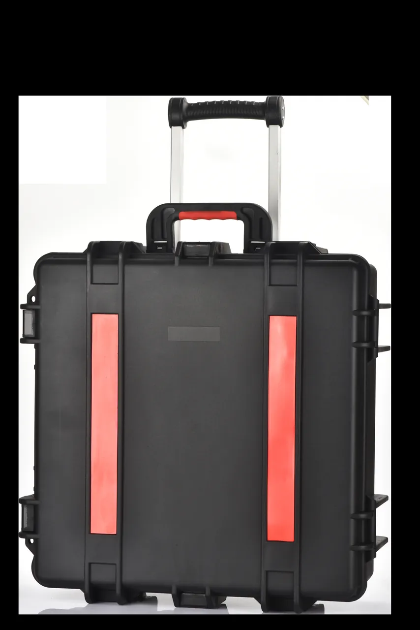
Nozzle protection rests on three points. Orifice protection: before packing, every bore receives a PP or nylon blind plug matched to its diameter, with an EPE ring over the plug. Axial restraint: nozzles are usually conical or stepped cylinders with an offset centre of gravity, so a plain foam cavity allows creep under vibration; a thermoformed EVA cradle with a cavity depth of at least 60 percent of part height and a separate support face for the flange is the reliable answer. Flange face protection: the sealing face is at once the most fragile and the most critical surface, so it is covered with a PET film before seating and never carries stacking load directly.
Cooling coils and jacket components are thin-walled cantilevers whose main failure modes are bending and pipe-end cracking. The usual remedy is a "support both ends, restrain the middle" cradle: EVA half-round pillows locate the two ends, PE baffles sit every 300 to 400 mm, and a thin IXPE layer between baffle and tube isolates and damps at once. Below DN25, bundles also need a PE wrap to stop tube-to-tube fretting that later becomes corrosion initiation.
| Part | Failure mode | Liner solution | Dimensional control | |||||
|---|---|---|---|---|---|---|---|---|
| --- | --- | --- | --- | |||||
| Feed nozzle | Orifice chipping, creep | Thermoformed EVA cradle + PP plug | Cavity depth >=60% of height, clearance <=1 mm | |||||
| Spray / distributor disc | Loss of flatness | Double-sided EPE + centre boss | Contact support >=70% of area | |||||
| Cooling coil | Bending, pipe-end cracking | EVA pillows + PE baffles | Support spacing 300 to 400 mm | Flange assembly | Sealing face corrosion | PET film + desiccant | Relative humidity <=40% RH |
Surface Treatment Coating Tanks: Packing Agitator Shafts and Dosing Parts
Surface treatment is where TiO2 gains its value, as hydrated oxides of aluminium, silicon and zirconium are laid down on the pigment surface to set weathering resistance, dispersibility and gloss. When an agitator shaft, impeller, dosing distributor or probe seat is removed from a coating tank, it usually still carries hydrated oxide slurry that dries into a hard scale — a material that both corrodes and contaminates.
An agitator shaft is the classic slender shaft with a large impeller combination, and the central risk is loss of straightness plus impeller distortion. A vertical hanging layout with a bottom restraint is preferred: a rubber-lined stainless hanger grips the shaft journal at one end, an EVA collar supports the tail at the other, and the impeller is removed and packed flat in a separate compartment. If the shaft must travel assembled, the case should be tall and narrow, with internal clear height at least 1.05 times the shaft length and a PE locating ring every 500 mm so lateral run-out stays within 2 mm under vibration.
Dosing distributors and probe seats are small, high-value parts and the ones most often damaged by casual stacking. Compartmentalise by function: every dosing line gets its own slot with a silicone plug in the open end, probe seats carry PP thread protectors before location, and any part that will touch the coating tank wall is kept away from carbon steel brackets and hand tools. Where cleanliness demands are higher, a removable PE inner liner creates a two-chamber case, as described in the Cleanroom Equipment Case guide.
| Part | Residue | Pre-treatment | Packing method |
|---|---|---|---|
| --- | --- | --- | --- |
| Agitator shaft | Hydrated oxide slurry | High-pressure wash + neutralise | Vertical hang + locating rings |
| Impeller | Scale, edge burrs | Deburr and polish | Flat EVA single-part cavity |
| Dosing distributor | Dilute acid, slurry | Rinse + air dry | Silicone plug + dedicated slot |
| pH probe seat | Buffer solution, salts | Deionised water rinse | PP thread protector + dry compartment |
Sand Mills and Bead Mills: Securing Dispersion Discs and Chamber Parts
Sand milling, or bead milling, is the key dispersion step for finished TiO2. Dispersion discs and chamber liners work under continuous high-speed impact from zirconia or glass beads, so by the time they are removed they often already carry fatigue cracks and wear steps. These parts are heavy, hard and sharp-edged, which makes them simultaneously the protected object and a potential source of damage to everything else in the case.
A dispersion disc is typically a multi-tooth or pin-type structure with stress concentration at the tooth tips. Discs should be packed flat with all tips facing the same direction, gaps between teeth filled with small EPE blocks to prevent hooking, and a 15 to 20 mm PE baffle between adjacent discs to avoid hard contact. Above 15 kg per disc, a ribbed tray liner becomes mandatory and local floor loading should be checked, because foam under long-term stacking compresses and loses its constraint. Cradle logic for comparable heavy parts is set out in the Ball Mill Liner Case article.
Chamber liners are thin-walled, large-diameter rings whose dominant failure modes are ovalisation and end-face damage. A full-wrap curved EVA cradle that locates the liner lying down on a 120-degree arc support, with PE end caps protecting the faces, is the recommended solution. Where the liner already carries a rubber or ceramic coating, any sharp support point can puncture the layer, so support must be area contact rather than point contact, with contact pressure below 0.05 MPa.
| Cushion option | Suitable parts | Thickness | Advantage | Caution |
|---|---|---|---|---|
| --- | --- | --- | --- | --- |
| EPE pearl foam | General metal parts | 20 to 30 mm | Low cost, easy to shape | Collapses under long compression |
| Thermoformed EVA | Precision and irregular parts | 30 to 50 mm | Tight fit, shape locking | Higher tooling cost |
| PE baffle | Disc and plate separation | 10 to 20 mm | Stiff, non-hygroscopic | Needs radiused edges |
| IXPE thin layer | Surface-sensitive parts | 3 to 8 mm | Fine cell, non-abrasive | Limited cushioning alone |
Gas-Powder Separation and Conveying Parts: Dust Ingress and Static Control
The separation and conveying stage handles classification, dedusting and transfer of finished and intermediate pigment. Typical parts include cyclone liners, filter bag cages, screw conveyor flights and rotary valve rotors. The priority here is not impact resistance but dust ingress prevention and static charge control.
TiO2 dust sits mostly between 0.2 and 0.5 microns and has outstanding hiding power. Once it reaches a case crevice it contaminates neighbouring parts and generates a secondary dust cloud at unpacking. Three rules follow. Minimise dead corners and avoid outward-facing thin-wall ribs with deep grooves. Use closed-cell liners rather than open foam, so dust cannot lodge in pores. Wipe or vacuum the case exterior before opening the lid, so the external dust layer is gone before the interior is exposed.
Static control matters just as much. Dry TiO2 powder generates charge readily during conveying and rubbing, and if electronic components or solvent-bearing parts share the case, a discharge can create a real hazard. Fit a removable conductive liner or anti-static foam layer, add an earthing stud, and put the earthing requirement in the packing documentation. For porous thin-wall items such as filter bag cages, a PE inner bag over the whole part before location prevents both dust and deformation.
| Part | Dust sensitivity | Static risk | Recommended measure | |||||
|---|---|---|---|---|---|---|---|---|
| --- | --- | --- | --- | |||||
| Cyclone liner | Medium | Low | Closed-cell liner + end-face protection | |||||
| Filter bag cage | High | Medium | PE inner bag + axial location | |||||
| Screw flight | High | Medium | Single-part compartment + anti-static layer | Dust filter cartridge | Very high | High | Full sealing + earthing stud |
Sulphate Route Corrosion: Concentrated Acid and Chloride Attack
The corrosion environment on a sulphate route line stacks three factors: dilute sulfuric acid, chloride ions and temperature. Ilmenite carries chlorine naturally and process water adds more Cl-, so even stainless parts face pitting and crevice corrosion. Grade 316L performs acceptably in dilute sulfuric acid at ambient temperature, but once the temperature passes 60 degrees Celsius and chloride exceeds 200 mg/L, the pitting potential falls sharply. Duplex steels and titanium perform better, but neither is immune.
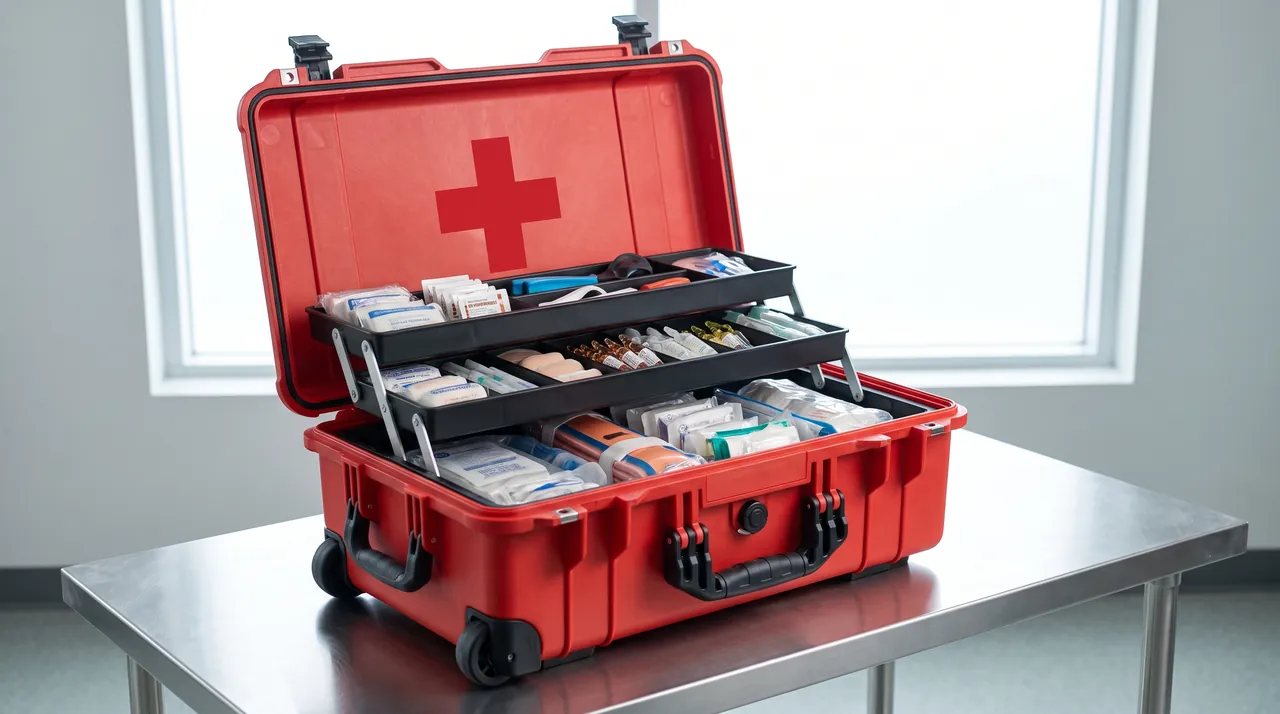
For the protective case, countermeasures split into an inside layer and an outside layer. Inside, every dismantled part completes a neutralise, rinse, dry sequence: neutralise residual acid to pH 6 to 8 with a 2 to 5 percent sodium carbonate solution; rinse with deionised water until the outlet chloride concentration falls below 50 mg/L, the step that matters most for titanium and stainless parts because Cl- directly triggers pitting; then blow cavities and blind holes dry with oil-free compressed air so no moisture remains to form a wet acidic micro-climate. Outside, the case must resist acid splash and salt fog, with silicone or fluoroelastomer gaskets and 316 stainless or zinc-flake latches and hinges.
The most direct way to judge a programme is salt spray verification. Under the neutral salt spray method of GB/T 10125, hardware should show no red rust after 240 to 480 hours; where acid mist settles on site, an acidified salt spray or cyclic corrosion test should be added. Duration and acceptance thresholds are discussed in the Salt Spray Corrosion Test reference and the guidance on Salt Spray Test Hours. For parts exposed to high chloride over the long term, the case material should be the modified PP or PC/ABS blend used in a Corrosion Resistant Enclosure rather than ordinary ABS.
| Corrosion factor | Typical condition | Effect on parts | Case response |
|---|---|---|---|
| --- | --- | --- | --- |
| Dilute sulfuric acid | 20 to 60%, 40 to 80 C | Uniform thinning | Neutralise + acid-resistant liner |
| Chloride ion | 200 to 2000 mg/L | Pitting, crevice corrosion | Rinse to Cl- below 50 mg/L |
| Acid mist deposition | pH 1 to 3 | Hardware rusting | 316 hardware + zinc flake |
| Marine salt fog | 5% NaCl, 35 C | Electrochemical corrosion | GB/T 10125 verification |
Material Selection: PP, ABS, PC and Stainless Steel Frames
TiO2 line components are generally heavy, and the journey may cross humid coastal routes, inland temperature swings and multiple handling cycles. Case material must therefore satisfy four requirements at once: impact resistance, chemical resistance, stackability and cleanability.
Polypropylene offers the best chemical resistance and is stable against dilute sulfuric acid, alkalis and salt solutions, but it is brittle at low temperature. ABS has good mechanical performance and mouldability, yet resists concentrated acid and long-term UV poorly. Polycarbonate delivers the highest impact strength and can be supplied transparent, but it is weak against alkalis, expensive and prone to stress cracking. The practical answer is a PP or PC/ABS alloy shell combined with a 304 or 316 stainless, or galvanised steel, frame: metal at the corners and stacking faces that carry load, polymer on the surfaces that meet chemicals.
| Material | Impact | Dilute acid | UV | Low temperature | Cost | Typical use |
|---|---|---|---|---|---|---|
| --- | --- | --- | --- | --- | --- | --- |
| PP | Medium | Excellent | Medium | Poor (brittle below 0 C) | Low | Coastal, chemical residue parts |
| ABS | Good | Medium | Poor | Medium | Medium | General structural parts |
| PC/ABS alloy | Excellent | Good | Medium | Good | Medium-high | Heavy precision parts |
| PC | Excellent | Medium | Medium | Good | High | Visible-contents requirement |
| Stainless frame | Excellent | Grade dependent | Excellent | Excellent | High | Stacking load structure |
Sealing Ratings: IP65/IP67 under IEC 60529 and GB/T 4208
The waterproofing requirement for TiO2 parts differs from that of electronics. What matters is protection against wash water and condensation, not prolonged immersion. IP65 means dust-tight and protected against low-pressure water jets from any direction; IP67 means dust-tight and protected against temporary immersion, normally 1 m for 30 minutes. Both are interpreted under IEC 60529 and its Chinese counterpart GB/T 4208. When sourcing, ask for a report stating the test conditions, duration and sample condition rather than a bare rating letter. The differences and test conditions are set out in the IP65/IP66/IP67 Difference note.
The selection logic is simple. If parts are neutralised and rinsed before packing and a desiccant is present inside, IP65 is normally sufficient. IP67 becomes necessary only for ocean freight, deck stowage, or where the customer explicitly requires a temporary immersion rating. One further point deserves attention: an IP rating says nothing about pressure differential tolerance. An IP67 case that goes through an air-freight pressure change without a pressure equalisation valve can be very difficult to open on arrival, and the gasket may even be drawn out of its groove.
| Rating | Dust | Water | Typical test condition | Typical use | ||||||
|---|---|---|---|---|---|---|---|---|---|---|
| --- | --- | --- | --- | --- | IP65 | Dust-tight | Water jet | 6.3 mm nozzle, 12.5 L/min | Routine inter-plant transport | |
| IP66 | Dust-tight | Powerful jet | 12.5 mm nozzle, 100 L/min | Open-air storage | ||||||
| IP67 | Dust-tight | Temporary immersion | 1 m / 30 min | Ocean freight, deck | ||||||
| IP69K | Dust-tight | Hot high-pressure water | 80 C, 8 to 10 MPa | Washdown areas |
Cushioning Liners: Layered EPE, EVA, PE and IXPE Combinations
Cushioning for TiO2 line parts is rarely a single material. It is a layered build following the logic of energy absorption outside, location in the middle, surface protection inside. The outer layer is usually EPE pearl foam, with low density and generous deformation travel for initial impact energy. The middle layer is a thermoformed EVA part that delivers three-dimensional location and constrains the component to its intended position. The inner layer is IXPE or a soft fabric facing that prevents hard material from contacting the part surface.
The governing parameters of a layered build are compression set and rebound. Static compression of the liner should stay within 15 percent of its original thickness, otherwise long-term stacking produces permanent collapse and the part loses restraint on the second journey. EVA and PU foams typically recover above 90 percent and suit repeated use, while EPE recovers around 70 percent and is better matched to one-way long-distance shipments. Above 30 kg per part, a PE load-spreading board beneath the liner turns a point load into an area load. A general comparison framework appears in the Case Internal Foam Types guide.
| Layer | Common material | Thickness | Function | Failure sign |
|---|---|---|---|---|
| --- | --- | --- | --- | --- |
| Energy absorption | EPE | 20 to 40 mm | Absorb impact energy | Local crushing |
| Location | Thermoformed EVA | 30 to 60 mm | Three-dimensional restraint | Polished cavity walls |
| Surface protection | IXPE / fabric | 3 to 8 mm | Prevent scratching | Fuzzing, detachment |
| Load spreading | PE board | 8 to 15 mm | Distribute point load | Bending |
Compartments, Latches and Hinges: A Traceable Internal Layout
Maintenance on a TiO2 line usually follows a pattern of removing one batch, packing one batch and shipping one batch. A single large cavity guarantees that parts will press against each other. The value of compartmentalisation is not only impact protection but the ability to count and trace every single item.
A sound layout separates a large main compartment, several small accessory slots, and an independent bay for consumables. The main compartment holds one part or one batch of identical parts, with PE baffles and EVA edge strips on the walls. Accessory slots are divided by function, with nozzles, bolts, gaskets and seal kits each getting a labelled slot. The consumables bay holds desiccant, anti-rust paper and spare parts away from direct contact with components. How heavy parts are combined inside one case is illustrated in the Chemical Reactor Parts Case compartment examples.
Latches and hinges are the parts you cannot see and that fail first. On a dusty, humid TiO2 site, an ordinary spring latch degrades once dust lodges in the mechanism and cycles accumulate. Specify a wide-body latch with a positive self-locking feature in 304 or 316 stainless steel, and a through-pin metal hinge of at least 4 mm pin diameter that has passed 5,000 open-close cycles. Lid opening should reach at least 100 degrees so tall parts can be lifted out without dismantling the case.
| Hardware | Common failure | Specification requirement | Verification |
|---|---|---|---|
| --- | --- | --- | --- |
| Latch | Spring fatigue, accidental opening | Stainless, anti-release | 5,000 open-close cycles |
| Hinge | Pin wear, fracture | Through-pin, diameter >=4 mm | 2x static load |
| Handle | Root cracking, deflection | Integrated with shell | 1.5x rated load |
| Gasket | Ageing, groove escape | Silicone / fluoroelastomer, retained | Compression set <=25% |
Pressure Equalisation Valves and Internal Temperature-Humidity Control
Exported TiO2 components frequently travel by sea and air, so a case sees significant pressure and temperature swings. A well-sealed case on an aircraft experiences falling external pressure and rising internal relative pressure, which pushes the gasket outward; after landing, rapid cooling creates a negative pressure that makes the lid hard to open. A pressure equalisation valve balances internal and external pressure in milliseconds while a labyrinth structure keeps liquid water and dust out. Valve selection and testing are covered in the Pressure Equalisation Valve Guide.
On temperature and humidity, the sensitive points for TiO2 parts are sealing face corrosion and moisture damage to electrical items. Desiccant is sized by free internal volume: 30 to 50 g of montmorillonite or silica gel per 0.1 m3 for routine shipments, rising to calcium chloride or a composite desiccant at about 100 g per 0.1 m3 with a humidity indicator card when the journey exceeds 60 days. Packing environment humidity should be at or below 60 percent RH, with an internal target at or below 40 percent RH. Parts carrying electronics, such as probes or transmitters, should first be vacuum packed in a foil bag.
| Parameter | Routine requirement | Long-cycle shipment | Verification |
|---|---|---|---|
| --- | --- | --- | --- |
| Internal relative humidity | <=40% RH | <=30% RH | Humidity indicator card |
| Desiccant quantity | 30 to 50 g per 0.1 m3 | 100 g per 0.1 m3 | Weight check |
| Valve opening differential | 3 to 8 kPa | 2 to 5 kPa | Differential pressure rig |
| Water ingress | No liquid water | No liquid water | IPX5 or better |
| Temperature range | -20 to 60 C | -30 to 70 C | Thermal cycling |
Stacking Load and Transport Testing: ISTA, GB/T 4857 and ASTM D4169
TiO2 components are heavy, so the bottom case in a stack may carry several hundred kilograms. Stacking design must therefore satisfy static conditions (long-term compression) and dynamic conditions (stability under transport vibration).
For static stacking, calculate the bottom load as single case weight multiplied by stack height multiplied by a safety factor of 1.5, and settle pallet dimensions and base structure at the design stage. Dynamic testing usually follows one of three systems: the ISTA series suits North American e-commerce and logistics chains, GB/T 4857 is the general Chinese method for transport packaging, and ASTM D4169 suits large equipment and intermodal journeys. Their emphases differ, so the specification should name the system, the distribution cycle and the assurance level. Test items and sequence for GB/T 4857 are summarised in the GB/T 4857 Transport Packaging article.

| Test system | Main items | Typical use | Key parameters | |||||
|---|---|---|---|---|---|---|---|---|
| --- | --- | --- | --- | ISTA 2A | Drop, vibration, compression | Combined packaging | Fixed and random vibration | |
| ISTA 3E | Unitised load testing | Palletised shipment | Incline impact, rotational drop | |||||
| GB/T 4857 | Vibration, impact, stacking | Domestic road and rail | Acceleration, stacking load | |||||
| ASTM D4169 | Combination by DC | Intermodal | Assurance level I/II/III |
Acceptance Criteria and Incoming Inspection Checklist
A protective case that is not inspected on arrival simply defers the risk to the loading dock. The purchase contract should carry a quantified acceptance clause supported by an incoming inspection checklist.
| Inspection item | Criterion | Method | Non-conformance action |
|---|---|---|---|
| --- | --- | --- | --- |
| Appearance | No cracks, sink marks or obvious colour deviation | Visual against sealed sample | Return or concession |
| Dimensions | Internal deviation <=+/-3 mm | Tape and calliper | Re-measure, then decide |
| Gasket | Flat joint, no groove escape | Visual plus hand pressure | Replace on site |
| Water resistance | No ingress after 10 min IPX5 spray | Spray test | Return whole batch |
| Latch | Smooth action, no binding | 50 cycles per unit | Replace hardware |
| Liner | Matches drawing, no missing corners | Drawing comparison | Re-make liner |
| Stacking | Deflection <=3 mm after 24 h at rated load | Static load test | Reinforce base |
| Documentation | Material cert, test report, packing drawing | Document review | Hold from stock |
Frequently Asked Questions FAQ
Q: Why can a feed nozzle from a titanium dioxide oxidation reactor not be packed with ordinary machine parts?
A: The failure threshold for a feed nozzle is extremely low. A 0.1 mm deviation in bore diameter changes the mixing ratio of titanium liquor and oxygen, which shifts crystal form and particle size distribution, and that in turn alters the brightness and tint strength of the finished pigment. In a mixed load the nozzle is crushed by heavier parts, and the flange sealing face and tapered orifice are the first surfaces to suffer. The correct approach is a dedicated thermoformed EVA cradle with a cavity at least 60 percent of part height, a PP blind plug in the bore, a PET film over the flange face, and a guaranteed orifice-to-cavity clearance of no more than 1 mm. If the nozzle must share a case, a PE baffle has to separate it physically from every other part, and its compartment must not carry any stacking load at all. The cradle should also be trial-fitted with the nozzle alone, so the fit is proven before the case leaves for its first shipment.
Q: To what standard should residual sulfuric acid and chloride on dismantled parts be treated before packing?
A: Run a closed loop of neutralise, rinse and dry. Neutralise with a 2 to 5 percent sodium carbonate solution by circulation or immersion until the cavity liquid reaches pH 6 to 8. Then rinse with deionised water until the outlet chloride concentration falls below 50 mg/L, a step that matters most for titanium and stainless steel parts because chloride is the direct cause of pitting, and because pitting that starts in a sealing face cannot be repaired in the field. Finally blow the cavity and blind holes dry with oil-free compressed air so that no residual moisture can form a wet acidic micro-climate inside a sealed case. Where a part has internal channels, pass the rinse water through the channels rather than only across the outside, and check the outlet with a chloride test strip. Record the pH and chloride values on the packing sheet so they serve as both acceptance evidence and traceability data for the receiving plant, and repeat the check whenever a part returns from service a second time.
Q: Should an agitator shaft from a coating tank be packed vertically or horizontally?
A: A slender shaft should be packed vertically or hung whenever possible. In a vertical position its own weight travels along the axis and bending is unlikely; laid horizontally, self-weight and vibration combine to produce sag that worsens as the span grows, and the sag is permanent once the yield point is passed. If case height forces a horizontal position, add a PE locating ring every 500 mm along the shaft, support both ends on EVA pillows, hold lateral run-out within 2 mm, and include a V-shaped brace to stop the shaft rolling. The impeller should be removed and packed flat in its own compartment, so that no cantilever bending moment develops at the shaft-to-impeller connection during handling and transport. On arrival, check straightness on a surface plate or with a dial indicator before the shaft goes anywhere near the coating tank, and record the reading against the value measured before dispatch. Mark the shaft with a paint stripe along one generator so that any twist as well as any bend becomes visible during the incoming check.
Q: Titanium dioxide powder has high hiding power and easily builds static. What special treatment does the case need?
A: The guiding principles are closed cell, few dead corners, and earthable. Avoid open-cell foam in the liner and use closed-cell EVA or PE instead, so dust cannot lodge in pores where it becomes impossible to clean out. Reduce grooves and narrow gaps inside the case so that a single wipe with a damp cloth reaches every surface, and radius the internal corners rather than leaving them square. Fit an earthing stud, and where necessary add a conductive liner layer whose surface resistance is stated on the test report. Before opening, wipe or vacuum the outside of the case so no dust cloud is raised at the moment the lid lifts, and unpack in a dedicated area with local extraction if the parts are going straight into a coating tank. If electronic items share the case, vacuum-pack them in a foil bag before they go in, and keep desiccant away from direct contact with sensitive components so that fine powder from the bag does not settle on connectors.
Q: How should IP65 and IP67 be chosen, and is a higher rating always better?
A: No, a higher rating is not automatically better. IP67 means temporary immersion, which requires tighter sealing and higher cost, but the main threat to titanium dioxide components is wash water and condensation, so IP65 is usually enough. IP67 is justified only for deck stowage on ocean freight, possible wave exposure, or a customer-specified immersion test. There is also a trade-off worth noting: the tighter the seal, the more pronounced the difficulty caused by pressure change, and an IP67 case will almost always need a pressure equalisation valve, otherwise the gasket is pushed out of its groove when the case is opened after air freight. When you compare quotations, ask each supplier to state the test method behind the rating, the duration used, and whether the test was done on a production unit or a prototype, because a rating letter alone tells you very little about field performance. It also helps to agree in writing which surfaces count as the protected volume, since a case can be IP65 overall while a hinge pocket still collects water.
Q: How should EPE and EVA foam be combined, and how do I know the cushioning is sufficient?
A: Follow the layered logic of energy absorption outside, location in the middle, and surface protection inside. Use 20 to 40 mm of EPE as the outer layer to absorb impact energy, 30 to 60 mm of thermoformed EVA as the middle layer for three-dimensional restraint, and 3 to 8 mm of IXPE as the inner layer against surface scratching. Above 30 kg per part, add a PE load-spreading board underneath to distribute the point load. Two checks tell you whether the build is adequate: static compression should stay within 15 percent of the original liner thickness, and after vibration or drop testing the cavity walls should show no polished patches, collapse, or signs that the part has migrated from its intended position. For repeated return journeys, prefer EVA or PU over EPE, because EPE recovers only about 70 percent and will slowly lose its grip after several trips. Label each cavity with the part number it was cut for, so that a liner is never reused for a heavier item than the one it was designed around.
Q: How much desiccant should go inside the case, and when should the approach change for longer journeys?
A: Size the desiccant against free internal volume. For routine shipments use 30 to 50 g of montmorillonite or silica gel per 0.1 m3 and target an internal relative humidity at or below 40 percent RH. When the journey exceeds 60 days, switch to calcium chloride or a composite desiccant with a higher moisture capacity, raise the quantity to about 100 g per 0.1 m3, and add a humidity indicator card so the condition can be checked if the case is opened en route. The packing environment matters too: keep ambient humidity at or below 60 percent RH, seal during the driest part of the shift, and record the sealing time and humidity on the packing sheet. Electronic items should be vacuum packed in a foil bag first. Finally, size the valve and the desiccant together, because a strong desiccant in a case with a leaking gasket will saturate long before the destination is reached. Write the desiccant mass and the target humidity on the outside label, so a receiving store can tell at a glance whether the case has already been opened in transit.
Q: Which hard acceptance criteria should be written into the contract for these protective cases?
A: Quantify the criteria in the contract rather than writing only that the cases must meet industry standards. Workable numbers include internal dimensional deviation within plus or minus 3 mm, no water ingress after a 10 minute IPX5 spray, 50 open-close cycles per latch with no binding or spring fatigue, static compression at rated load for 24 hours with no visible base deformation and deflection within 3 mm, gasket compression set no greater than 25 percent, and hardware showing no red rust after 240 hours of neutral salt spray under GB/T 10125. Also require the supplier to deliver a material certificate, test report and packing drawing with each batch, and agree the action for non-conforming lots, such as batch return, concession or rework. Sampling rather than 100 percent inspection is usually acceptable for appearance, but the water spray and stacking tests should be run on a first-article sample from every tool. Define the sampling plan and the acceptance quality limit as well, so both sides know in advance how many defects will trigger a hold.
Conclusion and Related Reading
Titanium dioxide line components need corrosion, deformation and cleanliness controlled together, fixed in a verifiable programme before shipment. JUNZHIJIA supplies compartment design, OEM/ODM production and shipping documentation, manufactured by Kexin New Materials (Guangdong) Co., Ltd.
Related Reading