

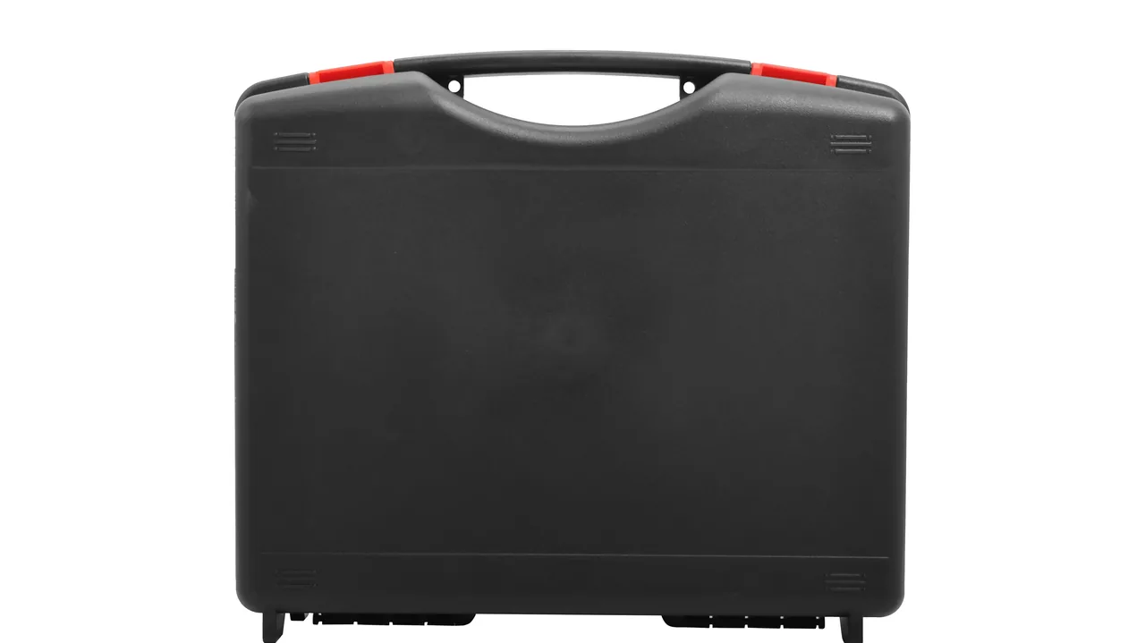
A vacuum coating machine is the anchor of a decorative, optical, display, semiconductor or energy-storage coating line. The two components that cost the most even when the power is off are the vacuum chamber and the target holder. A stainless chamber of 1200 mm diameter and 800 mm height typically holds flange flatness within 0.1 mm; press a dent into that flange and the chamber will leak once it is back on the machine. A magnetron backing plate carries internal coolant channels, and one impact depression can break the contact between target and plate, so an arc strikes inside the vacuum, shatters the target and seeds fragments across the chamber wall.
These parts travel repeatedly between factory delivery, line relocation, overseas delivery and factory overhaul, often covering thousands of kilometres through repeated handling and stacking. The chamber also carries an invisible liability: once evacuated, the atmospheric differential clamps the door hard against the flange, while the chamber wall, the O-rings, the backing plate and the coated parts all outgas, slowly releasing adsorbed gas and water vapour that can break the leak-up rate at any moment.
Transport protection for vacuum chambers and target holders is not a matter of building a thicker box; it is a matter of locking four indicators at once, namely the direction of clamping force, the isolation of outgassing sources, zero contact on sealing faces, and zero particulate migration, with every step traceable. JUNZHIJIA uses compartmented liners, suspended flange support, individually sealed O-ring pouches and an arrival test record so the chamber can go straight onto the pump stand and the target holder can accept a target without rework.
Table of Contents
- Chamber Door Compression Under Atmospheric Differential and Vent Sequence
- O-Ring Outgassing, Aging and Independent Pouching
- How Coated Workpieces Outgas and Collapse the Vacuum Hold
- Chamber Particulate Migration and the Pinhole Root Cause Chain
- Backing Plate Replacement: Impact Damage and Fragment Risk
- Cathode Cooling Line Residue and Target Utilization
- Stainless Steel and Titanium Flange Denting and Rust Bloom
- Vacuum Valves and Shutter Assemblies: Anti-Clog Packing
- Film Stress, Substrate Flatness and Stacking Load Limits
- Arrival Leak-Up Rate Re-Test Procedure and Acceptance Criteria
- Intercontinental Humidity Swing and Target Back Plate Hygroscopic Effects
- Compartment Layout, Packing Documents and Opening Inspection
- Frequently Asked Questions FAQ
- Conclusion and Related Reading
Chamber Door Compression Under Atmospheric Differential and Vent Sequence
The most under-estimated mechanical fact about a vacuum chamber is how hard the door is pressed once evacuated. The clamping force equals atmospheric pressure multiplied by the projected sealing area: F = 0.1013 MPa x S. For a circular door of 800 mm diameter the projected area is roughly 0.50 m2, so at 1 Pa the door is held by about 50 kN, equivalent to a five-tonne weight bearing on the flange. Twelve M16 bolts tightened to 30 Nm deliver about 10 kN each, which looks adequate, yet the distribution is uneven. Regions with wide bolt pitch or a slightly out-of-flat flange yield first, and plastic deformation spreads from the inside outward.
| Door Diameter | Projected Sealing Area | Clamping Force at 1 Pa | Recommended Uniform Bolts |
|---|---|---|---|
| --- | --- | --- | --- |
| 500 mm | 0.20 m2 | about 20 kN | 8 x M12 |
| 800 mm | 0.50 m2 | about 50 kN | 12 x M16 |
| 1200 mm | 1.13 m2 | about 115 kN | 16 x M20 |
| 1600 mm | 2.01 m2 | about 204 kN | 24 x M20 |
This table explains why a chamber must not be shipped while still under vacuum. Temperature cycling makes the internal gas pressure swing repeatedly, and vibration lets the flange bolts creep against their seats, so preload distribution is clearly worse after several hundred kilometres. The opposite case is more dangerous. If an evacuated chamber is struck, the trapped gas compresses almost instantly, a few micrometres of closure equals several hundred pascals, local stress can exceed the yield strength of stainless steel, and a permanent indentation appears. The chamber then fails its leak-up test on site, and a dent rather than a scratch makes responsibility hard to assign.
Control of pressure state at sealing is therefore strict. JUNZHIJIA completes a vent cycle before packing, records the final value, confirms the chamber sits within 500 Pa of ambient, and seals immediately. Venting order matters too: with a gate valve, evacuate the foreline first, open the gate valve second, break the chamber last. Such valve parts are compartmented as described in Pump, Valve and Fitting Cases.
O-Ring Outgassing, Aging and Independent Pouching
The O-ring is the largest outgassing source inside a coating chamber, contributing an order of magnitude more gas than the chamber wall adsorption layer. Rubber is a porous material loaded with gas absorbed during vulcanization and mixing, and once exposed to vacuum that gas is simply extracted, producing a steady pressure rise.
| Process Step | Common O-Ring Material | Temperature Limit | Outgassing Character | Selection Note |
|---|---|---|---|---|
| --- | --- | --- | --- | --- |
| Room-temperature magnetron sputtering | NBR, nitrile | about 100 C | Low outgassing, high compression set risk | Suits ambient door and feedthrough seals |
| Arc target and high-temperature evaporation | FKM, fluorocarbon | about 200 C | Heat resistant, higher long-term outgassing | Pair with bake-out pumping |
| High-temperature bake station | VMQ silicone | about 200 C | Outgassing and tear risk combined | Poor tear resistance, guard against puncture |
| Ozone and ultraviolet exposure | EPDM | about 150 C | Excellent aging resistance | Not compatible with mineral oil or vacuum grease |
The weakness of NBR is not temperature but compression set. Once the door bolts are tightened, the ring is held under continuous compression, and if the transport cycle exceeds thirty days the three-dimensional network in the compound creeps slowly. On arrival the ring may look perfectly elastic, yet the preload has already dropped and the leak-up rate follows. Acceptance is a feeler-gauge measurement of compression, not a fingernail test. Normal installation sits between 15 and 25 percent; below 10 percent indicates under-compression, above 35 percent indicates over-compression and the start of accelerated compression set.
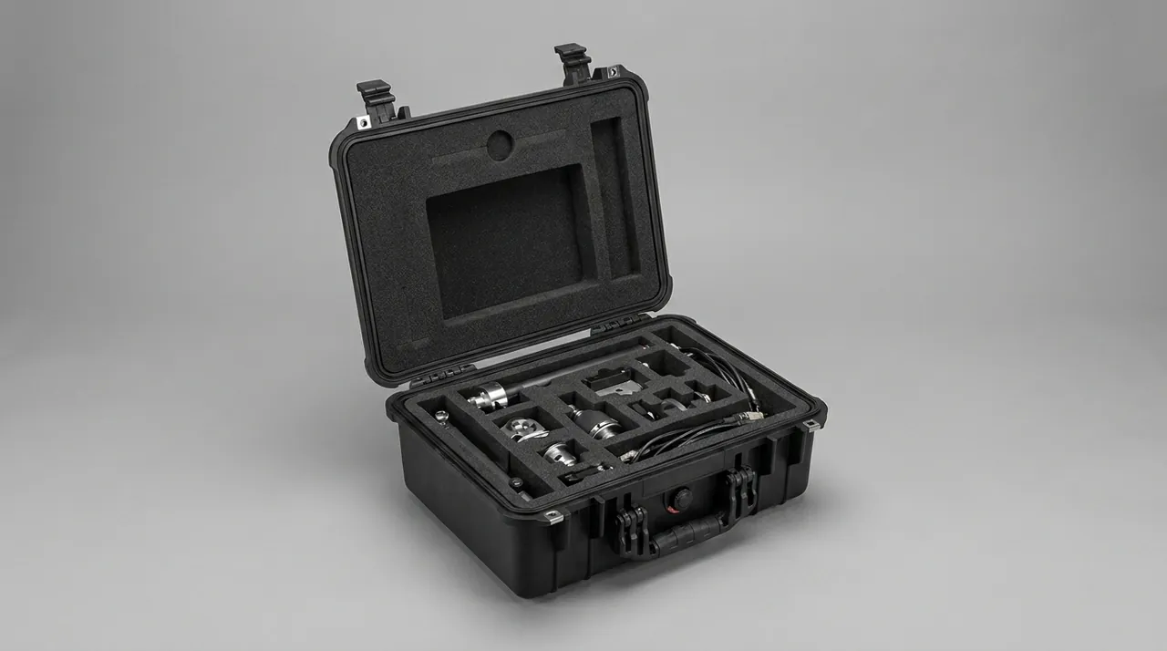
The packing rule is that O-rings travel separately from metal parts. JUNZHIJIA cuts an individual clean pouch per size, using clean polyethylene rather than ordinary PE film so static and particulate release are both controlled. Each pouch carries size, compound, Shore A hardness, quantity and batch. Nothing except desiccant goes inside, so the ring is never squeezed or rubbed, and the pouch is anchored in a small dedicated compartment near the chamber, never resting on a flange and never adjacent to a metal backing plate. Replacement details are covered in What to Do When a Protective-Case Gasket Ages and How Do You Replace a Protective Case Gasket.
How Coated Workpieces Outgas and Collapse the Vacuum Hold
When leak-up performance falls, the first assumption is usually that water entered the box. In a real coating chamber the more common culprit is the workpiece itself. Outgassing sources rank roughly as follows: O-rings and sealing compound first, then chamber wall adsorption and trapped volumes, then the backing plate and target surface, then the coated substrate, and finally welds and feedthroughs.
Workpieces contribute in two distinct modes. The surface adsorption layer consists mainly of water vapour and solvent residue from cleaning, and it releases at room temperature. Bulk outgassing occurs inside porous materials, where ceramic substrates, porous glass, sintered metal parts and roughened surfaces store gas in their pore structure, and that gas emerges substantially only when the part is heated to 150 to 250 C. The first mode finishes within roughly thirty minutes of pumping; the second concentrates during bake-out. If a line pumps to target at room temperature and starts production, vacuum often rebounds once the workpieces heat up, and film thickness drifts with it.
| Outgassing Source | Room-Temperature Behaviour | Bake-Out Behaviour | Effect on Leak-Up Rate | Control During Transport |
|---|---|---|---|---|
| --- | --- | --- | --- | --- |
| O-rings and sealing compound | Continuous and slow | Accelerates markedly | Dominant, sets the pressure-rise curve | Individual clean pouch, no heat, no squeeze |
| Chamber wall adsorption layer | Front-loaded, then decaying | Accelerates markedly | Extends pump-down time | Control internal humidity, no bare-part shipment |
| Coolant residue in backing plate | One-off large burst | Residual boiling | Can emulsify pump oil | Blow dry and cap every port |
| Porous coated substrate | Low steady output | Concentrated release | Vacuum rebound after startup | Bake out, then double-bag clean |
One counter-intuitive rule follows. A chamber should not be sealed for shipment with workpieces still inside unless they have been fully baked and double-bagged. If the chamber must travel with its load, parts are cleaned, dehydrated, double-bagged, and the chamber gets desiccant plus three humidity indicator cards placed at the flange, below the target holder and at the lowest point of the floor. This slows release; it cannot eliminate it, and should be presented as a compromise rather than a fix. The cleanroom practice behind this reasoning appears in Cleanroom Equipment and Filter Cases.
Chamber Particulate Migration and the Pinhole Root Cause Chain
In coating work, pinholes and particle defects account for most quality escapes, and the chain of traceability usually ends at the transport step. The chamber interior is a closed clean island, so any particulate introduced while loading is picked up by the gas stream once pumping starts and carried toward the walls and target area. Once deposition begins, the particle either becomes a pinhole or punches through the film.
Sources rank cleanly by responsible step:
| Particulate Source | Typical Size | Migration Path | Traceable Feature | Control Measure |
|---|---|---|---|---|
| --- | --- | --- | --- | --- |
| Liner foam shedding | 50 to 500 um | Falls in during loading | White or grey fibre | Closed-cell liner plus clean film facing |
| O-ring wear debris | 20 to 100 um | Released by repeated assembly | Rubber crumbs in flange grooves | Dedicated clean mat, never assemble above an open chamber |
| Chamber wall rust particles | 5 to 80 um | Entrained by gas flow | Rust speckles and oil film | Passivation, no long bare stainless exposure |
| Target spatter fragments | 10 to 300 um | Fall from target face | Bright metal flakes below target | Separate compartment plus physical baffle |
| Handling dints and weld spatter | 30 to 200 um | Knocked loose in transit | Rust concentrated on corners | Corner wrap, no bare steel on sealing faces |
There is a useful diagnostic rule for pinhole mapping. When pinholes correlate spatially with the target holder position, the prime suspects are spatter fragments or backing plate residue. When they are randomly scattered yet improve after a chamber clean, cleanliness is the likely root cause. When they cluster at substrate edges or near clamp points, stress and shadowing deserve attention. Compartment design pays off here: shipping the target holder apart from the chamber, and double-bagging fragile coated parts, converts an indistinguishable mixed contamination into separable units with their own evidence.
Cleanliness specification follows the process. Decorative coating typically calls for chamber wall roughness of Ra 0.8 um, while optical coating asks for Ra 0.4 um with controlled visible particle counts. The liner choice cannot therefore chase maximum cushion density. Any surface touching the chamber should use closed-cell EVA or IXPE rather than open-cell EPE, because open-cell foam behaves like a sieve under vibration and squeezes particles out of its own depth. A two-layer build works well: a high-density outer layer against impact, a closed-cell inner layer against the part.
Backing Plate Replacement: Impact Damage and Fragment Risk
The target holder is not a fit-and-forget component. When target utilization drops, the target is changed, which means removing the backing plate, clearing residue from the target face, fitting a new target and re-checking parallelism. On down-shaft machines this is routine maintenance; on up-shaft and multi-target designs it may have to happen from outside the chamber.
Three risks dominate that operation. The first is impact damage at the plate edge. Backing plates normally carry threaded holes and locating bosses that register against the target base, and once a hard object raises a burr on the boss rim, the target cannot sit flat inside the chamber. Glow discharge concentrates in that gap and within seconds burns a crater into the target edge, throwing fragments across the chamber wall and shield. The second is collision on the coolant side. Internal coolant passages terminate at faces and seals that, if dented, allow water into the target base or the chamber, and the leak-up rate degrades immediately. The third is loss of small parts. Target clamps, retaining tabs, insulator shims and grounding springs ship as sets; once they scatter in transit, the field spends extra days reconstructing the set, and clamp thickness from a different batch shifts contact pressure on the target.
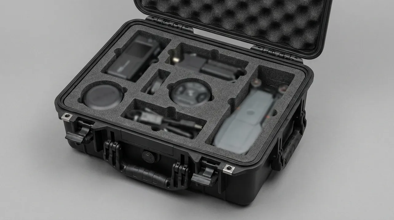
JUNZHIJIA assigns the backing plate its own rectangular compartment with full-perimeter location. Two cushion layers sit underneath: a high-density layer that absorbs forklift impact and a profiled moulded layer matching the plate outline on four sides. Fifteen millimetres of clearance is left directly above every locating boss and threaded hole, and no hard stop block may press on a boss. Clamps, retaining tabs and shims travel in a separate accessory box divided from the plate compartment, and the box has a transparent lid so the count can be verified without disturbing the main cavity.
Cathode Cooling Line Residue and Target Utilization
Magnetron backing plates carry internal coolant passages, and arc cathodes need water or oil cooling as well. Even when a chamber ships disassembled, the circuits in the plate and cathode may retain a small quantity of working fluid after the factory drain, and the harm from that residual keeps deteriorating through the journey:
- Freeze damage. A hold in an ocean container or air freight hold can drop below 0 C, and water in the passage freezes and expands, splitting the channel or pushing a fitting off. The leak only shows when water is flushed through at commissioning.
- Microbes and odour. Water standing in a sealed chamber for weeks supports microbial growth and acid attack on aluminium channels and stainless fittings.
- Pump oil emulsification. Residual liquid drawn into the backing pump mixes with the oil into an emulsion, ending pump oil life immediately.
The control sequence has three steps: blow dry with dry air or nitrogen, fit every port with a genuine blind plug or dust cap marked as sealed, and add desiccant with an indicator card. Newspaper and tape are not acceptable substitutes, because printing ink is itself an outgassing source.
On target utilization, the transport phase does not protect a utilization figure; it protects the geometric relationship between plate and target base. Low utilization normally comes from target face shading, uneven magnetic field distribution, a poorly seated back face that triggers glow discharge, or arc length settings. If the plate bows in transit, the gap between target and base becomes visible on reassembly, glow concentrates in the gap, and consumption becomes uneven immediately. The plate therefore travels flat and must never be stood on edge or suspended. Structural practice for heavy elements is covered in Heavy Duty Cases.
Stainless Steel and Titanium Flange Denting and Rust Bloom
The flange is the most expensive flat surface on the chamber and the one with no tolerance at all. It seals against the O-ring, forms the clamp with the door bolts, and serves as the vacuum datum, so any dent, burr or scratch changes the compression pattern directly.
| Flange Material | Common Grade | Corrosion Behaviour | Primary Risk | Protection Requirement |
|---|---|---|---|---|
| --- | --- | --- | --- | --- |
| Austenitic stainless | 304 / 316L | 304 pits in coastal air, 316L more stable | Rust bloom from free-iron contamination | Electropolish plus clean film, no direct carbon steel contact |
| Duplex stainless | 2205 | High, strong in chloride media | Hard, lower toughness | Reinforce corners, avoid point-loaded impact |
| Titanium and alloys | TA2 / TC4 | Excellent | Native oxide affects downstream adhesion | Nitrogen or vacuum sealing, no acid mist and no bare hands |
| Copper and alloys | C1100 | Good | Deforms, dents are unrecoverable | Support the rear face, never point contact |
| Hard anodised aluminium | 6061-T6 anodised | Moderate | Film cracking and flaking | Thicken corners, prevent hard scratching |
Rust bloom on stainless steel is frequently blamed on water ingress, but the dominant cause is free-iron contamination. When a chamber has contacted carbon steel tools, bolts or iron swarf during machining or service, that free iron sits on the surface and produces brown rust as soon as humidity arrives. The spots return shortly after wiping, and the wiping itself tends to leave fine scratches. Prevention targets contact sources: no bare carbon steel may act as a contact surface inside the case. Supports, straps and fasteners should be stainless or coated anodised aluminium, and every strap landing point gets a soft pad.
Titanium presents the opposite problem. Its native oxide film ranges from grey to golden, and that film directly affects adhesion in later heat treatment and coating steps. A breathable dust cover is only a physical barrier; it does not stop residual moisture and hand oils from migrating outward over a long journey, and localised oxide colour shift then appears after delivery, producing colour difference and uneven adhesion that are expensive to repair. The correct approach is full-surface clean polyethylene film pressed into the edges, or nitrogen sealing with aluminium tape on the seal line. Clean handling practice is illustrated in Optical Lens and Coated Element Cases.
Vacuum Valves and Shutter Assemblies: Anti-Clog Packing
A coating machine carries a fair number of vacuum valves: angle valves, straight-through valves, gate valves, needle valves, plus shutters and their drive mechanisms. Vulnerability does not track price, and the two items most often destroyed in transit are the needle valve and the shutter.
The needle valve meters gas or back pressure through a fine conical stem pressed into its seat by a screw thread. Transit vibration lets residual metal swarf, a foam fibre or a single dust particle into the valve opening, where the stem jams part-way. The result is either a valve that will not shut, so atmosphere control drifts during coating, or a restricted opening that caps pump-down speed. Neither fault raises an alarm; the machine simply produces film thickness that is subtly wrong, and that behaviour is rarely traced back to shipping. The shutter fails differently. It must stroke quickly inside the chamber to shadow the target, and its drive end is often a toothed linkage or a pneumatic rod. If that linkage bends in transit, the stroke no longer completes, the shutter does not close, and the target face is attacked continuously during every target change.
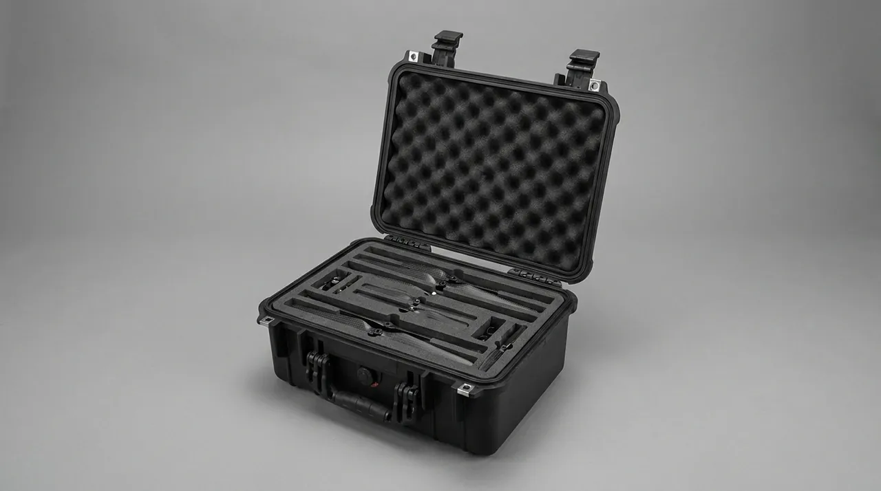
The packing rule is that vacuum valves are bagged individually, every port receives a proper protective cap rather than tape, rod-type assemblies get end stops with a do-not-side-load marking, and all chamber interfaces are closed with blind flanges so nothing enters the piping from outside. No paper document may sit directly above a chamber opening, because paper lint is a direct source of fibre-scale particulate. Breathable vent hardware is specified separately in How to Choose a Pressure Equalization Valve for a Protective Case.
Film Stress, Substrate Flatness and Stacking Load Limits
Film stress accumulated during deposition stays in the workpiece after it leaves the chamber. A compression-dominated film bends thin substrates toward the coated side, while a tensile-dominated film warps the other way. The deformation already exists when the part is removed, and transport vibration plus stacking load amplify it. Several already-curved glass sheets stacked in soft foam contact more tightly as the stack grows, so sliding during transit creates edge-to-edge point contact where the curvature is largest.
Two design layers address this. First, fragile coated parts are separated one layer at a time with at least 8 mm of clearance, filled with closed-cell foam blocks rather than thin non-woven sheets; adjustable dividers suit low-volume repeat orders where the same part returns repeatedly, while profiled foam suits mixed loads. Second, support points land on non-coated faces: frames or rear faces for glass and mirrors, and burrs, gates or process datums for metal. Third, stacking limits are marked on the case together with single-unit mass and centre of gravity, so the site does not add tiers to save floor space. This matters because stacking load transfers into thin-wall welded chamber structures, where sustained line load drives fatigue cracks near welds.
Film also reacts to environment. Functional films including conductive, high-reflection and optical layers can absorb moisture, shift stress and even delaminate in high humidity. As-coated parts must be stored apart from bare parts so that sliding metal does not scratch a film. If condensation is found inside the package on opening, moisture must be dealt with before the chamber is opened, because a film of water on the chamber wall becomes the dominant outgassing source during pump-down. The same condensation logic is discussed in Environmental Chamber Cases.
Arrival Leak-Up Rate Re-Test Procedure and Acceptance Criteria
The decisive action after a chamber arrives is a leak-up rate re-test. It is the only objective evidence of whether transit caused a leak, and it asks not merely whether the chamber can be pumped down, but how long it holds after the pumps are isolated.
The procedure runs as follows. Confirm the chamber exterior shows no impact dents and no rust bloom, and that flanges and O-rings are clean and free of debris. Confirm all interfaces are refitted exactly as shipped, including gauges, gauge ports, shutter drive and feedthroughs, with blanking plates in their original positions. Rough down with the mechanical pump to below 5 Pa, then close the isolation valve. If an ion pump or turbomolecular pump is fitted, bring it to rated frequency in the specified sequence. Record the starting pressure, which should be at or below 1 Pa, and the start time. Hold for ten minutes and record the pressure rise. Convert the result to an empty-pump rate in Pa/h or a leak rate in mbar.L/s, then compare against the acceptance table.
| Chamber Volume | Empty-Pump Rate Limit, Ten-Minute Hold Converted to Pa/h | Engineering Interpretation |
|---|---|---|
| --- | --- | --- |
| Up to 0.3 m3 | 30 Pa/h or lower | Standard release, acceptable |
| 0.3 to 1.0 m3 | 20 Pa/h or lower | Standard release, acceptable |
| 1.0 to 3.0 m3 | 10 Pa/h or lower | Extend the test to a 24 hour confirmation |
| Above 3.0 m3 | 5 Pa/h or lower | Ship a 24 hour pressure-rise curve as a release document |
When the test fails, the investigation order must be fixed rather than jumping to the conclusion that transit damaged the body. Check the O-rings first, looking for inverted insertion, twisting, missing lubricant and compression set. Then check the flange faces for dents, burrs and debris. Then check the valves, especially needle and gate valves for sticking and particle debris on seats. Then check interfaces for missing blanks, loose clamps and leaking gauge ports. Only after all four is it reasonable to look at chamber welds. In practice the first four categories account for most failures, and every one of them is recoverable on site. The result should be recorded either way: JUNZHIJIA supplies an arrival re-test record sheet with measurement conditions, ambient temperature and humidity, start pressure, hold duration, end pressure and instrument identifier, filed alongside the packing photographs so a later dispute can separate transit damage from misuse.
Intercontinental Humidity Swing and Target Back Plate Hygroscopic Effects
The route from an inland factory to a port, from the port to the customer site and from the airport to the cleanroom usually makes humidity harder to predict than temperature. The interior environment of the chamber is set by three things: residual adsorbed gas, residual cooling liquid, and sealed air.
The backing plate tolerates humidity well, but its surface condition changes with it. An aluminium plate grows a thicker oxide layer in humid air, which can change contact resistance once a target is fitted. A copper plate develops green basic carbonate when damp, and that deposit must be removed mechanically to restore seating. Stainless backing plates pit in the presence of residual chloride. Control starts with moisture barrier wrapping such as vapour inhibitor paper or a gas-phase bag around the plate before it enters the chamber, plus a humidity indicator card in the target holder compartment, read before any cleaning decision is made.
A second law of intercontinental transport is easy to miss. For every 10 C of temperature rise, the absolute pressure of non-condensable gas rises by roughly 35 percent. Nitrogen trapped in a chamber at 5 C on a winter plateau reaches 35 C inland in summer, so internal pressure climbs by about a third. On an inward-opening door without a gate valve, that pressure lifts the door and shears the sealing lip. This is the classic damage mode when goods leave a high-altitude origin and are delivered at altitude. Prefer machines with gate valves for shipment, or depressurise the chamber slightly and fit a pressure indicator. The outer case itself needs an equalisation path so ambient pressure does not drive trapped gas toward the door. Gasketed box design is covered in Sealed Protective Boxes and Latch-Sealed Cases.
Compartment Layout, Packing Documents and Opening Inspection
A qualified chamber and target holder case is not a box of mixed parts; it is a compartment system organised by assembly sequence and contamination class. A four-level layout works well:
| Level | Contents | Design Requirements |
|---|---|---|
| --- | --- | --- |
| Level 1, bottom | Chamber body and flange support | Load bearing, supports the flange rear face, no point contact |
| Level 2 | Backing plate, target base, coolant circuit parts | Full-perimeter location, laid flat, clearance above bosses |
| Level 3 | O-ring pouches, clamp accessory box, valves | Separated from each other, no direct metal-to-metal contact |
| Level 4, top | Coated parts, as-coated parts, humidity cards | Clean double-bagging, clean barrier layer above Level 3 |
Packing documents are part of the chamber delivery, and a missing item causes rework during commissioning. JUNZHIJIA supplies a document set containing the packing list with case number, part number, net weight, gross weight, dimensions and centre of gravity; the liner profile drawing with compartment numbering and per-part location method; the O-ring list with size, compound, hardness, quantity and batch; the desiccant specification and quantity record; the humidity indicator card placement map; the arrival re-test record sheet; the opening inspection procedure; and packing photographs taken both before and after closure.
Opening inspection follows a fixed sequence, because the wrong order directly causes damage. First inspect the outer case for crushing, water marks and tilt impact, then read the humidity card and photograph it. Open the lid only, without tilting the box, so contents stay in place. Confirm the document set is complete and the numbers match the case. Remove layers from level 4 down to level 1, supporting each part from underneath rather than gripping flanges or tube stubs. Inspect piece by piece: wipe the flange with white cloth and examine under oblique light for dents, check boss and coolant ports on the plate, and confirm O-ring pouches match the specified size and batch. Finally reassemble and run the leak-up re-test described above, filing the data. Feed the inspection photographs and test results back to the packing party as input for the next batch. Liner tooling and profiling are covered in Custom Foam Inserts, material options in What Are the Types of Internal Foam for a Protective Case, and cleaning restrictions under How to Clean and Maintain a Protective Case.
Frequently Asked Questions FAQ
Q: Can a vacuum chamber be sealed for shipment while it is still under vacuum?
A: It is not recommended, and the reason is not leakage. Shipping the chamber evacuated may look like a proven seal, but temperature cycling in transit makes the internal gas pressure swing repeatedly, and vibration lets the flange bolts creep against their seats, so preload distribution is clearly worse after several hundred kilometres. The more dangerous case is an impact while evacuated. The trapped gas is compressed almost instantly, a few micrometres of closure equals several hundred pascals, clamping force can double locally, and the flange takes a permanent indentation that no cleaning will remove. The chamber then fails its leak-up test on arrival with no obvious external trace. The correct practice is to complete a vent cycle before sealing, record the final value, confirm the chamber sits within 500 Pa of ambient, and seal immediately. Keep a gauge port readable from outside the box so the customer can confirm the sealing state at unpacking, and record ambient temperature at sealing so a pressure rise in transit can be separated from a warm box.
Q: Is it acceptable to ship the O-rings inside the same chamber case, and why do they need separate pouches?
A: Separate pouches are strongly recommended for three reasons. Material compatibility comes first. NBR, fluorocarbon and silicone differ widely in temperature rating and media resistance, so sharing a pouch with the chamber offers no way to isolate temperature rise or residual media, and summer heat inside a sealed box can age the compound before installation ever happens. Cleanliness isolation comes second. Once a seal picks up metal swarf or fibre, the debris ends up in a flange groove at assembly and becomes a leak path that shows up as a slow pressure rise rather than a clean failure, which is far harder to diagnose. Traceability comes third. An individual pouch labelled with size, compound, Shore A hardness, quantity and batch makes arrival counting immediate, and a shortage or a mismatch can be judged on the spot rather than discovered during commissioning. Nothing except desiccant should sit inside the pouch, so the ring is never squeezed, stretched or rubbed in transit, and the pouch is anchored in its own compartment where no metal edge can press the sealing cross-section.
Q: Can a backing plate lie flat on foam, and what support does it actually need?
A: It may lie flat, but it needs full-perimeter location with the locating bosses kept in clearance. Two failure modes matter in transit. The first is a burr raised on an edge or boss by a hard object, and once that burr exists the target cannot seat flat, glow discharge concentrates in the gap, and a crater forms in the target edge within seconds. The second is a bow that ruins back-face seating against the target base, producing the same glow in a different place. The buffer arrangement answers both. A high-density layer underneath carries forklift and stacking load, while a profiled moulded layer matches the plate outline on four sides. No hard stop may press directly on a threaded boss, so at least 15 mm of clearance must remain above them. The plate must travel flat, never on edge or suspended, and the maximum stacking tier must be marked on the case and enforced on site. Where the plate is heavy enough to need two people, lift it from beneath rather than by the threaded bosses, since a boss is a sealing-adjacent feature and not a lifting point.
Q: Should coated workpieces travel inside the chamber, and what does that cost?
A: Only if they have been baked out and double-bagged in clean film. Coated workpieces are the second largest outgassing source after O-rings. Surface adsorption releases at room temperature, while gas trapped in the pore structure of porous substrates comes out in a burst once the part heats up. Sealed inside a chamber, that gas has nowhere to go. Pump-down slows, the vacuum rebound during warm-up shifts film thickness, and a batch that passed qualification can drift out of specification without any obvious alarm being raised. If parts must ship in the chamber, clean and dehydrate them, double-bag them in clean film, place indicator cards at three points, and load desiccant generously. This slows the release but cannot remove it, so present it to the customer as a compromise with a stated residual risk. Where the process allows, shipping the chamber empty and the parts in a separate clean case is the only fully effective option, because it removes the substrate from the outgassing equation entirely rather than merely delaying it.
Q: The chamber will not pump down on arrival. Is transport necessarily to blame?
A: Do not jump to that conclusion; follow a fixed investigation order. Start with the O-rings, checking for inverted insertion, twisting, missing lubricant and compression set. Next inspect the flange faces for dents, burrs and trapped debris. Then check the needle and gate valves for sticking and particle debris on their seats. Then verify blanking plates, clamp torque and gauge port fittings. Only after those four are clean should chamber welds be considered. In most real failures the first four categories dominate, and all are recoverable at the site without returning the chamber to the factory. Note also that a reading taken on a cold machine is meaningless, so warm the chamber and the pumps to the specified temperature, and run the full ten-minute hold rather than extrapolating from the first two minutes, because a fast initial rise and a slow steady rise point to entirely different faults. Whatever the outcome, record ambient temperature and humidity, start pressure, hold duration, end pressure and instrument identifier, and keep that record with the packing photographs.
Q: Why must titanium flanges be sealed rather than simply dust covered?
A: Because a dust cover is only a physical barrier. The native oxide on titanium ranges from grey to golden and directly affects adhesion in later heat treatment and coating steps. A fabric cover cannot stop residual moisture and hand oils from migrating outward over a long journey, and localised oxide colour shift then appears after delivery, producing colour difference and uneven adhesion that are expensive to repair. Wrap the entire face in clean polyethylene film pressed into the edges, or seal under nitrogen with aluminium tape on the closure line, and record the nitrogen fill pressure on the accompanying document so the customer can verify the seal is still intact. Titanium must never touch carbon steel, flange faces must not be handled bare-handed, and every strap landing point needs a soft pad so no point load reaches the machined face. The same discipline applies to the stainless parts travelling in the same package, since free-iron contamination and moisture attack produce similar-looking stains but need entirely different responses, and misdiagnosing one as the other wastes a maintenance window.
Q: Brown rust spots on a stainless flange, does that mean water entered the case?
A: Not necessarily. Free-iron contamination is the dominant cause. When a chamber has met carbon steel tools, carbon steel bolts or iron swarf during machining or service, that free iron sits on the surface and generates brown rust as soon as humidity arrives. Wiping it away usually leaves fine scratches, and the spots return within a short period because the source is untouched. Prevention targets the contact sources: no bare carbon steel may be a contact surface inside the case, supports and strap pads should be stainless or coated anodised aluminium, and straps need soft pads. Cleaning stainless with plain water and a wire brush is the most common avoidable mistake. Use a stainless-specific agent and a lint-free cloth, then repassivate, rather than assuming the surface is restored. Abrasive methods that scratch the passivation layer should be avoided, because a scratched surface rusts sooner than the original one. Distinguishing the two causes is straightforward once the history is known: water-driven rust appears as scattered pitting on upward-facing surfaces where condensation sat, while free-iron rust appears as streaks and patches directly below fasteners, tool marks or former carbon steel contact points.
Q: Does stacking tiers of chamber cases actually cause harm?
A: Yes, and the effect is badly underestimated. Stacking load transfers through thin-wall welded chamber structures. A chamber is a welded thin shell, not a solid pressure vessel, and sustained line loading drives fatigue cracks near welds that may stay invisible for months. Coated fragile parts also suffer: when already-curved sheets are stacked with uneven support, sliding during transit creates point contact at the high points of the curvature, amplifying existing film stress into bowing and scratches. Mark the maximum tier, single-unit mass and centre of gravity on every case, enforce it on site, separate coated parts one layer at a time with at least 8 mm of clearance, and land all support points on non-coated faces. Where stacking is unavoidable, insert load-spreading plates so the tier above does not concentrate force on one boss or one flange region.
Conclusion and Related Reading
Vacuum chamber and target holder protection merges three disciplines into one verifiable packing logic. JUNZHIJIA builds compartmented interiors, suspended flange support, individually sealed O-ring pouches and full arrival documentation to order, including tooling and OEM/ODM.
Related Reading