

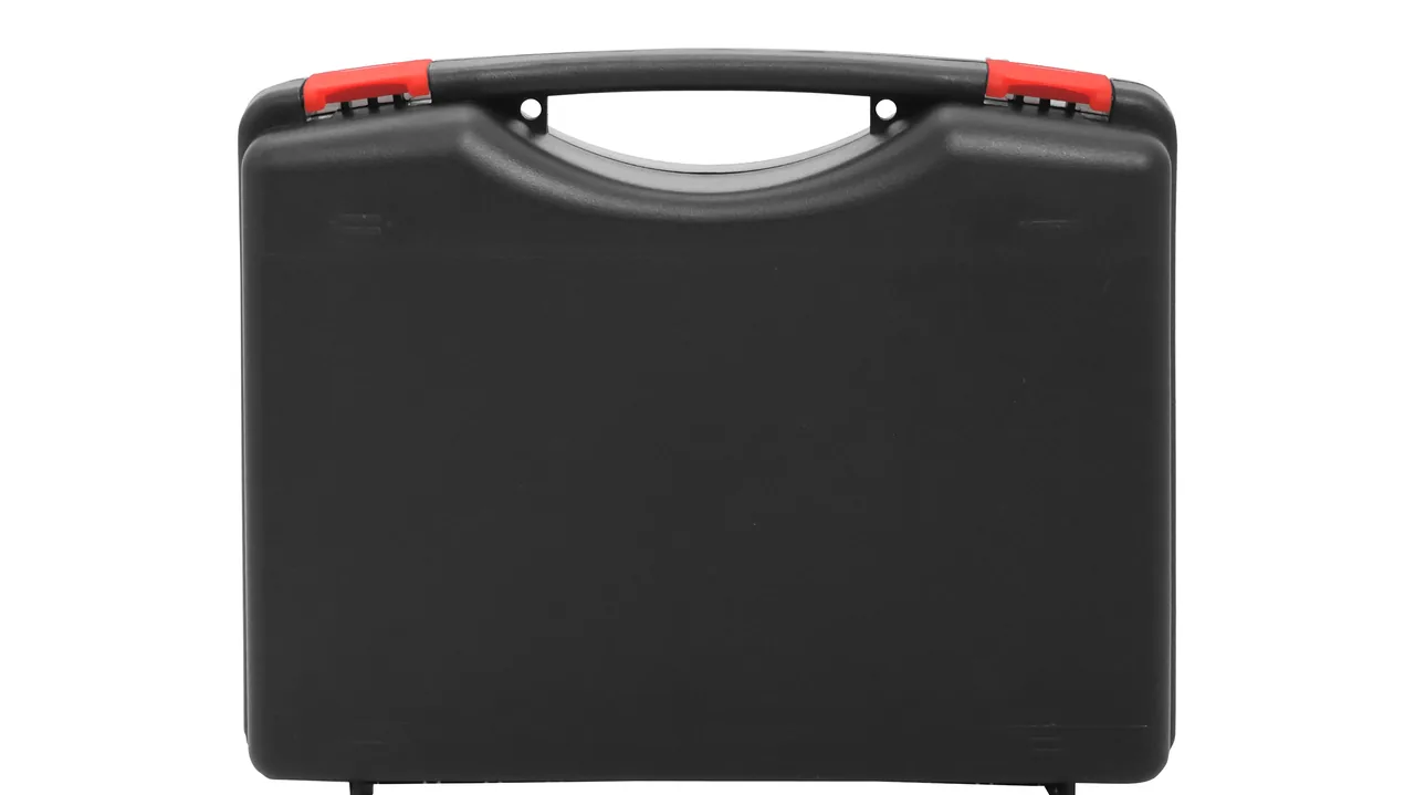
On a TFT-LCD or OLED generation line, a glass substrate is rarely touched by hand. Vacuum suction pads lift it out of the cassette, gantry robots carry it between stations, bonding rollers and alignment mechanisms laminate the polariser onto the substrate, and AOI plus lighting-test modules judge every sheet. These parts live inside an ISO Class 4 to 6 cleanroom at roughly 22 °C and 45 % RH. The moment they are shipped back for repair, transferred between plants, or delivered from an equipment builder to a panel maker, they enter an environment that looks nothing like the fab: road vibration, loading impacts, humid docks, and day-night temperature swings. Damage on a panel line part rarely shows up as a cracked shell - it shows up on arrival as a scored suction face, a gantry beam that no longer runs straight, a camera whose sensor has drifted a few microns from its lens, or liner debris sitting on an optical surface.
JUNZHIJIA holds that a display panel part case has to solve cleanliness, static dissipation, micro-vibration damping, dimensional restraint and moisture resistance on one drawing at the same time - not as a sealed box with a slab of foam dropped in at the end. This article works through the failure mechanisms by part family, then covers shell structure, sealing and cushioning, and finishes with test and acceptance methods that a procurement team can actually write into a specification.
Table of Contents
- Cleanliness and Precision: Two Constraints in a Display Panel Fab
- Vacuum Transfer Suction Pads and Gantry Beams
- Bonding Rollers and Alignment Parts in the Lamination Stage
- Inspection Modules (AOI / Lighting Test) and Precision Guideways
- Particle Control: What the Case Itself Emits
- ESD Discharge Paths for Sensitive Boards and Sensors
- Case Material and Structure: Cleanroom Compatibility versus Stiffness
- Sealing System: IP65, IP67 and IEC 60529 / GB/T 4208
- Cushioning Liners: EPE, EVA, PE and IXPE
- Compartments, Latches, Hinges and Pressure Equalisation Valve
- Stacking Load and Transport Testing: ISTA, GB/T 4857, ASTM D4169
- Temperature, Humidity, Salt Fog and Fab Environments (GB/T 10125)
- Customisation, OEM/ODM and Acceptance Criteria
- Frequently Asked Questions FAQ
- Conclusion and Related Reading
Cleanliness and Precision: Two Constraints in a Display Panel Fab
A panel fab holds temperature near 22 ± 1 °C and relative humidity near 45 ± 5 % RH, with even tighter control at coating and photolithography stations supported by fan filter units and chemical filters. Once packed, the case interior becomes a sealed micro-environment that must handle five jobs on its own: keep particles out, give static charge somewhere to go, attenuate the 5 to 200 Hz band of transport vibration, restrain the sag of long cantilever parts, and resist moisture and salt fog. These jobs pull against each other. Sealing the case hard to stop moisture lets pressure differentials from altitude and temperature suck the gasket inward. Clamping a part tightly enough to stop movement may leave a permanent flat spot in a rubber-coated roller.
Arrival damage on panel line parts usually falls into four families. Contact damage covers a scored ceramic suction face or a rubber cover dented by a sharp corner. Geometric drift covers a gantry beam bent out of straightness, a guideway mounting face twisted, or an alignment datum pin shifted. Contamination damage covers liner debris on an optical surface or plasticiser vapour condensing on a lens. Electrical damage covers an ESD-sensitive board punctured at its input stage or a scale reader head degraded by moisture.
The first real selection step is not choosing a box size but sorting the manifest by sensitivity type: deformation-sensitive parts such as gantry beams and guideways, surface-sensitive parts such as suction faces and roller covers, electrically sensitive parts such as driver boards and reader heads, and contamination-sensitive parts such as lighting-test filters. Only then do you decide which parts share a cavity. JUNZHIJIA repeats this in every panel project: group first, then cut the mould, or the case will hide cross-vibration and cross-contamination problems until arrival.
Vacuum Transfer Suction Pads and Gantry Beams
A vacuum transfer unit combines the suction pad, its air fittings and a gantry beam. Pads are usually porous ceramic, PEEK or a carbon-fibre composite disc, and the flatness and roughness of the suction face decide how reliably the substrate is held. Gantry beams are aluminium extrusions or carbon-fibre square tubes that can exceed two metres, which makes them classic slender cantilevers. Mounting blocks are stainless or aerospace aluminium with precision threaded holes. Each family fails differently, so the protection priority differs too.
| Part | Typical failure | Mechanism | In-case countermeasure |
|---|---|---|---|
| --- | --- | --- | --- |
| Porous ceramic pad | Scored suction face, blocked pores | Hard particles pressed into the surface; debris migrating under vibration | Film-level face isolation, non-shedding liner, anti-static bag around the pad |
| PEEK pad | Warped disc, deformed lip | Long-term lateral load or stacked weight | Custom pocket location; never stack pad on pad |
| Carbon or aluminium beam | Straightness out of tolerance, local denting | Beam bending under road vibration when supports are too far apart | Multi-point support along the beam, spacing set by beam stiffness |
| Air fitting | Loose fitting, compressed seal | Thread back-off under high-frequency vibration | Separate small cavity, anti-loosening restraint at the fitting |
| Stainless mounting block | Damaged threads, bruised mating face | Part-to-part impact | One pocket per block, pocket walls with radiused edges |
For a suction face, non-contact is often safer than soft contact. The common method is to bag the pad in a clean anti-static sleeve, then let it drop into an EVA pocket cut to its profile so the pocket only locates rather than supports the pad. The suction face looks into open space and never touches a liner surface. Beam support has to be calculated, not guessed: start with the two ends and the midpoint as the minimum three supports, then add supports based on how closely the beam's first bending mode aligns with the transport vibration band. Transfer units are usually held to the same cleanliness class as the host tool, and the cleanroom-compatible materials and liner practice described in Cleanroom Equipment Transport Protection apply directly to the in-fab packing step.
Bonding Rollers and Alignment Parts in the Lamination Stage
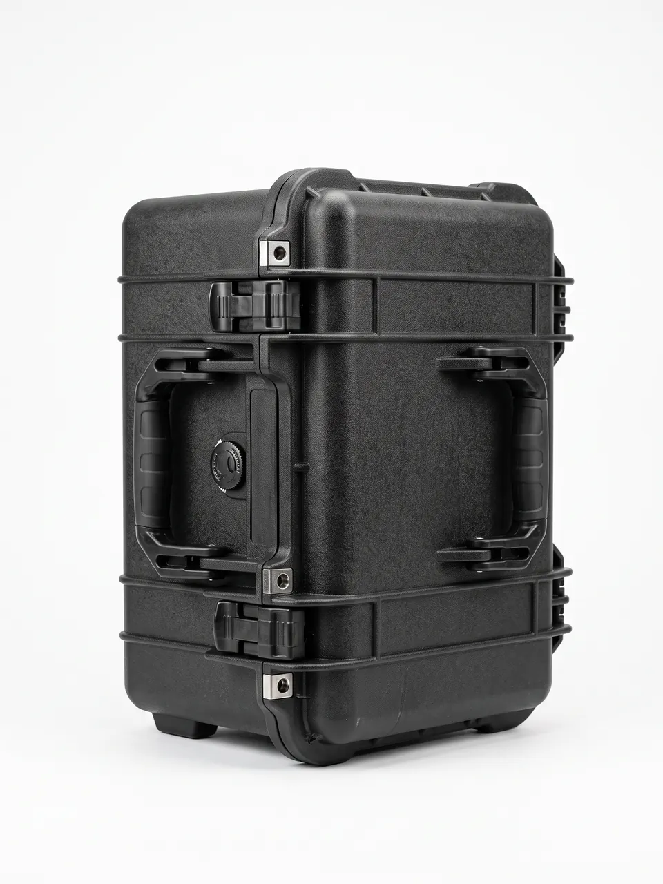
Bonding rollers are normally rubber-covered, with silicone or nitrile covers in the 40 to 70 Shore A range. Roller roundness and the straightness of the face line determine bubble rate and pressure uniformity; once a cover is dented by a foreign object, the whole roller has to be recovered. Alignment parts include datum pins, precision slides, scale mounting blocks and servo couplings, all micron-level datum components. What these parts share is that they fear pressure, sharp contact and torsion.
| Object | Sensitive quantity | Main threat in transit | Recommended practice |
|---|---|---|---|
| --- | --- | --- | --- |
| Rubber roller cover | Roundness, face straightness, cover integrity | Contact with other parts, sharp corner damage, sustained point pressure | Lay the roller in a V-shaped soft cradle, cradle on non-working areas, no hard contact |
| Roller journal | Coaxiality | Bending when both ends hang free | Two supports at the journals; never suspend by one end |
| Alignment datum pin | Position tolerance, surface roughness | Impact, thread loosening | Pin into a dedicated locating hole, chamfered entry, wrapped pin |
| Precision slide | Preload, mounting-face flatness | Ball micro-motion under vibration, corrosion | Lock mid-stroke, desiccant in the cavity |
| Scale mounting block | Flatness, thermal stability | Micro-distortion under humidity and temperature cycling | Isolated cavity, away from hygroscopic materials |
A rubber roller tolerates point contact worst of all. If a two-metre roller rests on a single foam block at mid-length, vibration keeps pressing the roller into the same spot, and after a few hundred kilometres a visible flat is possible. The correct approach is at least two or three V- or U-shaped soft cradles along the roller, placed at the journals or on non-working areas, with 3 to 5 mm of clearance between the cover and the liner. Alignment parts sit at the level of precision gauges, and their packing logic follows the same order used in Precision Instrument Transport Protection: locate first, restrain second, cushion last, and never reverse the order.
Inspection Modules (AOI / Lighting Test) and Precision Guideways
AOI cameras combine a lens, a sensor and a light source; lighting-test modules carry a power board and a signal board; precision guideways are usually crossed-roller or linear types paired with an optical scale for closed-loop positioning. The critical quantity for this group is not absolute strength but relative position. If the lens and sensor drift only a dozen microns apart, image sharpness and defect thresholds shift with them; if the gap between a guideway and its reference scale changes, repeatability drops.
Transport vibration has three broad segments. Loading impacts concentrate in 1 to 20 ms with high amplitude but few cycles. Road vibration concentrates in 5 to 50 Hz with moderate amplitude over a long duration. Rail and sea transport add low-frequency sway. For optical and guideway components, the real danger is resonance - when the road excitation frequency meets the natural frequency of the part-plus-liner system, the motion is amplified. Liner design therefore cannot chase softness alone; it has to tune the rebound behaviour so the system's natural frequency stays away from common excitation bands.
| Vibration source | Frequency character | Risk to inspection and guideway parts | Countermeasure |
|---|---|---|---|
| --- | --- | --- | --- |
| Manual handling and drops | Single high-amplitude shock | Lens-to-sensor relative shift | Thick cushion wall plus travel limiters to cap peak acceleration |
| Road transport | Continuous 5 to 50 Hz | Amplified response distorting imaging | Liner rebound tuned off the resonance band |
| Rail and sea | Low-frequency sway and micro-vibration | Ball micro-wear, datum micro-slip | Guideway locked mid-stroke, anti-slip pads at mating faces |
| Multiple transfers | Cumulative repeated shock | Fastener back-off | Thread locking plus arrival torque re-check |
Where a product has already been through a whole-machine vibration survey, the packing transport can be read against the points raised in Transport Vibration and Resonance Testing: first establish the resonance point, then work back to liner density and thickness. Storage of AOI cameras and lens modules can follow the compartment and dust-control practice collected in Machine Vision Camera Transport Protection, with one extra rule - the light source module and the lens must not share a cavity in contact.
Particle Control: What the Case Itself Emits
Panel parts are far more particle-sensitive than ordinary machine parts. A particle a few tens of microns across on an optical surface can trigger a false call in lighting test, and a fibre from the liner entering a guideway raceway causes sticking. Internal cleanliness is therefore the first threshold a panel part case must clear, and the contamination sources fall into three groups: what the case material emits and sheds, what the liner foam outgasses and breaks into, and what the packing process drags in from outside.
| Source | Symptom | Control | Verification |
|---|---|---|---|
| --- | --- | --- | --- |
| Wood and corrugated shells | Fibre, dust, pests | Switch to aluminium or stainless inner liner | Wipe sampling with particle count within limit |
| Standard EVA or PE foam | Plasticiser vapour, crumbs | Low-outgassing grade with clean pre-conditioning | Volatiles check and debris inspection |
| Adhesives and labels | Residual glue, paper dust | Wrap without labels, move markings to the outer case | No residue on optical surfaces |
| Packing environment | Skin flakes, lint | Pack in a clean zone or clean bench | Arrival particle spot check |
| Repeated open-close wear | Broken liner edges | Radius liner edges and add edge binding | Visual check after cycling |
Two lessons are worth stating. First, a metal liner is not automatically clean: an aluminium liner that still carries machining fluid after production will slowly outgas, so the liner must be degreased, cleaned and clean-wrapped before parts go in. Second, cleanliness and moisture control pull against each other, because hygroscopic materials absorb water but also shed. The safer combination keeps desiccant sealed in its own sachet away from the parts rather than laying absorbent material beside them. Front-end panel and semiconductor handling share this logic, and Semiconductor Electronics Handling and Clean Protection sets out a fuller cleanliness classification and bench requirement that can be used as the reference for in-fab packing.
ESD Discharge Paths for Sensitive Boards and Sensors
The suction pad body is often non-conductive, but the vacuum generator on the transfer unit, the driver boards in the lamination stage, the CCD and signal-processing boards in the inspection module, and the scale reader head are all ESD-sensitive devices. Static causes two kinds of harm: a discharge after triboelectric charging can puncture a gate oxide or a CMOS input stage, and a charged surface attracts particles that then contaminate an optical face. Static control is not about preventing generation; it is about draining charge slowly and keeping it away from sensitive parts.
| Measure | Mechanism | Installation point | Target parameter |
|---|---|---|---|
| --- | --- | --- | --- |
| Dissipative liner | Gives static charge a controlled drain path | Surface resistance held in the dissipative band | 10⁶ to 10⁹ ohms |
| Anti-static clean bag | Isolation and drainage at once | Bag close to the part without rubbing | Same band as the liner |
| Grounding terminal | Leads charge to the outside | Grounding stud on the case, bonded to the fab earth | Lowest practical resistance |
| Faraday shielding bag | Blocks external static fields | For bare boards and CCD modules | Metallised film intact, no breaches |
| Humidity coordination | Drying and static suppression conflict | Avoid over-drying while keeping ESD control | Balance the two requirements |
Note that the cleanroom instinct of "drier is better" does not apply to static control, because very low relative humidity raises triboelectric voltages sharply. The compromise is a limited desiccant charge, a humidity indicator card and a dissipative liner, with the card read on arrival. The systematic treatment of ESD Anti-Static Protective Case Design covers resistance zoning and grounding in a way that also fits panel line parts.
Case Material and Structure: Cleanroom Compatibility versus Stiffness
A panel part case has to be cleanroom-compatible and static-dissipative, survive stacking and drops, and open inside a cleanroom without raising dust. Common base materials are copolymer PP, glass-fibre reinforced PP, PC/ABS, an aluminium frame with skins, and stainless inner liner assemblies. The decision turns on the trade between weight, stiffness, cleanliness and cost.
| Base option | Stiffness / load | Cleanliness | Weight | Best fit |
|---|---|---|---|---|
| --- | --- | --- | --- | --- |
| Copolymer PP | Medium | Good, low outgassing | Light | Small and mid-size parts, repeated rotation |
| Glass-fibre reinforced PP | High | Good, dimensionally stable | Medium | Beams and guideways needing stiffness |
| PC/ABS | High, good impact | Medium, needs clean grade | Medium | Precision parts with drop risk |
| Aluminium frame with skins | High, scalable to large sizes | Good | Medium | Large gantries, whole modules |
| Stainless inner liner in a frame | Depends on frame | Excellent | Heavier | Optical parts with the tightest cleanliness demand |
Three structural details are commonly overlooked. The first is the balance between wall thickness and ribs: simply thickening a wall adds mass, whereas a sensible rib layout raises bending stiffness at equal weight, which matters most on cases longer than two metres. The second is the load path through the base: a heavy part should transfer force through the liner straight into the case floor, and from there into the pallet or vehicle deck, rather than routing it through side walls and corner fittings. The third is cleanability of the inner surfaces: deep blind grooves and square internal corners cannot be wiped properly, so radiused transitions cut both cleaning effort and particle retention. Large panel part packaging shares ground with Photomask and Reticle Transport Protection, where structural rigidity matters more than cushion thickness.
Sealing System: IP65, IP67 and IEC 60529 / GB/T 4208
IEC 60529 splits enclosure protection into two digits: the first for solid foreign objects and dust, the second for water. China's GB/T 4208 adopts the same system. A first digit of 6 means dust cannot enter at all; a second digit of 5 means the case survives water jetted from any direction, and 7 means short immersion at a specified pressure and time without ingress. Whether a panel part case needs IP65 or IP67 depends on whether the route ever offers a chance of being submerged.
| Rating | Test condition (summary) | Typical route | Suitable for panel parts |
|---|---|---|---|
| --- | --- | --- | --- |
| IP54 | Limited dust protection, splash resistant | Indoor shuttles, dry loading | In-fab transfer only |
| IP65 | Dust-tight, jet-water resistant | Plant transfers, loading in rain | The usual threshold for most panel parts |
| IP67 | Dust-tight, short immersion | Open port storage, monsoon transfer | Export sea freight or exposed sites |
| IP69K | Dust-tight, high-pressure hot water | Washdown environments | Rarely required for panel parts |
Two clarifications matter. An IP rating describes the shell's resistance to water and dust; it says nothing about internal cleanliness or cushioning performance. Also, the gasket is a consumable: silicone tolerates temperature and ageing well but recovers a little slowly, while nitrile resists oil better but weathers sooner, so the compression set and hardening should be checked periodically. Sealing and pressure equalisation are one system, and valve selection should follow Pressure Equalisation Valve Selection.
Cushioning Liners: EPE, EVA, PE and IXPE
The liner is what actually touches and protects the part; the shell only carries the external load. The four common foams behave quite differently, and a panel part case usually needs a mix rather than one material throughout.
| Foam | Density and feel | Energy absorption | Cleanliness | Recommended use |
|---|---|---|---|---|
| --- | --- | --- | --- | --- |
| EPE | Light, quick rebound | Good for many small impacts | Moderate, needs clean grade | Outer cushion, void filling |
| EVA | Medium, thermoformable | Precise location, stable under load | Good in low-outgassing grades | Formed locating pockets for precision parts |
| PE foam | Firmer, closed cell | Good load bearing and compression resistance | Fairly good | Base support for heavy parts |
| IXPE | Thin, cross-linked closed cell | High cushioning in thin layers, fine surface | Good, suitable for facing | Optical face isolation, thin cavity shims |
The general combination logic is to support and locate heavy or long parts on PE or high-density EVA at the base, absorb impact at the sides and top with EPE or EVA, and add a fine IXPE facing where an optical or mirror surface sits. How an EVA pocket is formed affects both accuracy and cleanliness, and EVA Thermoformed Liner Process covers the tooling, heating and setting steps. Thicker is not automatically better: the thickness should be calculated from the allowable acceleration and the stiffness of the protected part, because an oversized cushion can let the part drift inside the cavity.
Compartments, Latches, Hinges and Pressure Equalisation Valve
Putting parts with different sensitivity profiles into one cavity is the most common mistake in panel part cases. Compartmenting serves three purposes: vibration isolation, contamination isolation and impact prevention. Fixed dividers, removable dividers and nested sub-boxes are the three common approaches, chosen by how often the load combination changes.
- Fixed dividers: the stiffest option, best for a stable production rotation, but a new configuration needs new tooling.
- Removable dividers: a blend of flexibility and stiffness for mixed loads, provided each divider has a positive locating feature so it cannot shift.
- Nested sub-boxes: sensitive small parts get their own inner case before going into the main cavity, giving the best isolation.
Latches and hinges carry the open-close life and the sealing compression. Panel part cases are opened frequently for inspection, so latch cycle life and hinge rigidity are key indicators, and the clamping force has to be even so no section of the gasket sits under-compressed for long. The pressure equalisation valve solves the side effect of good sealing: the tighter the case, the larger the differential across it as altitude and temperature change, until the gasket is either sucked in or pushed out. A waterproof breathable valve with an ePTFE membrane balances pressure while blocking water, which is why it is common on long sea and air shipments. The interaction of these three elements is compared in Dividers versus Foam Liner Design.

Stacking Load and Transport Testing: ISTA, GB/T 4857, ASTM D4169
Panel part cases mostly travel between plants or for export, so stacking and transport tests cannot be skipped. Stacking load starts with the loaded mass of one case multiplied by the expected number of tiers, plus a safety factor, and the interface between case base and pallet must avoid localised point loading or the lowest side walls will buckle first.
| Verification item | Purpose | Method family | Result of interest |
|---|---|---|---|
| --- | --- | --- | --- |
| Whole-case transport performance | Overall handling and transit tolerance | ISTA whole-case procedures | No failure of shell or liner |
| Vibration and shock | Assess resonance amplification and fastener back-off | GB/T 4857 series | No part movement, no loose fasteners |
| Drop impact | Assess sealing and liner after corner, edge and face drops | Drop portion of GB/T 4857 | Sealing intact, liner unbroken |
| Stacking pressure | Assess creep and buckling under long storage | Combined static and dynamic stacking | No collapse, no permanent set |
| Distribution cycle simulation | Cover multi-leg combined stress | ASTM D4169 distribution cycle | Pass at the chosen assurance level |
| Air transport low pressure | Assess sealed cavity differential | Low pressure with temperature cycling | Gasket not sucked inward |
A test method only gives comparability; it does not replace an assessment of the actual route. The pragmatic sequence is to set the test level by the harshest leg - say export sea freight with several transfers - and then use in-case recorders or arrival inspection to verify it. For whole-case testing, insert the real liner and the real load, otherwise the result describes a box rather than the packaging system. Cross-border route comparison is set out in Case Logistics for Cross-Border and Sea Freight.
Temperature, Humidity, Salt Fog and Fab Environments (GB/T 10125)
Panel fabs cluster in coastal and humid southern regions, and exports add an ocean crossing with heavy salt exposure, so corrosion and moisture control are long-term concerns. The neutral salt spray test in GB/T 10125 uses a 5 % sodium chloride solution at 35 °C with continuous spraying, and it is the usual way to rank the corrosion resistance of metal parts and surface finishes. A panel part case is mostly plastic, so the real focus is on hardware, hinges, latches and inner liners.
| Environmental factor | Affected item | Mechanism | Countermeasure |
|---|---|---|---|
| --- | --- | --- | --- |
| High humidity | Circuit boards, optical scale | Insulation drop, micro-corrosion of metal | Limited desiccant plus humidity indicator card |
| Salt fog | Hinges, latches, stainless parts | Chloride ions break the passive film | 316 stainless or passivation treatment |
| Day-night temperature swing | Gaskets, cavity pressure | Breathing repeatedly draws in moisture | Breathable valve plus elastic gasket design |
| Low temperature | Foam, rubber parts | Rebound loss, low-temperature embrittlement | Low-temperature flexible grades, avoid over-compression |
| Cleanroom environment | Liner, case surfaces | Cross-contamination | Wipe the outer case before entry, clean the inner case |
Two points deserve emphasis. First, a salt spray test ranks different schemes against each other; it cannot be converted directly into field life, and it does not support any certification claim. Second, an outer case used near a cleanroom should be wiped and pre-cleaned before entry so that ordinary warehouse particles are not carried into the clean zone. The corrosion and moisture strategy is developed further in Salt Spray Corrosion Testing for Cases.
Customisation, OEM/ODM and Acceptance Criteria
Panel line parts are usually non-standard, so customisation is close to unavoidable. On projects of this kind JUNZHIJIA works through a fixed sequence - sort the manifest, model the liner, validate a sample case, run a small trial batch, freeze the production design, then deliver with documentation - rather than quoting and cutting a mould immediately. Once a case mould is wrong, no liner change can repair a load path that was wrong from the start.
| Stage | Input | Output | Pass marker |
|---|---|---|---|
| --- | --- | --- | --- |
| Manifest sorting | Part list, sensitivity profile, route | Draft compartment plan | Which parts share a cavity is agreed |
| Liner modelling | Part 3D data, allowable acceleration | Liner 3D and forming plan | Location and support points confirmed |
| Sample validation | Sample case, real load | Test data and improvement list | Tests pass, arrival shows no anomaly |
| Small trial batch | Frozen drawings and process | Trial production | Dimensions and appearance pass sampling |
| Production freeze | Inspection spec, batch records | Stable supply | Batch consistency within tolerance |
| Delivery with case | Delivery list | Test report, liner drawings, instructions | Documents complete and traceable |
Acceptance is best split into two levels: factory and arrival. Factory level checks shell dimensions and wall thickness, gasket contact, latch cycling, liner location and cleanliness. Arrival level checks the outer case for impact and water traces, reads the humidity indicator card, and looks for part movement, contact marks, or contamination on optical and roller surfaces. Batch purchasing should also fix the sampling ratio and the non-conformance process. The wider interface and responsibility split for volume customisation is covered in OEM/ODM Custom Protective Cases. This batch of panel part cases is designed and produced by Kexin New Materials (Guangdong) Co., Ltd., with liner drawings and inspection records archived with each shipment.
Frequently Asked Questions FAQ
Q: Should the suction face of a vacuum transfer pad point up or down inside the case?
A: Pointing up is the more robust choice. The suction face is sensitive to both precision and cleanliness, so facing it upward stops debris, liner crumbs or condensation from settling onto it during transport. Facing up also lets the face hang free and carry none of the pad's own weight, which prevents the lip from deforming under long-term compression. If the pad must face down, leave enough clearance beneath the face and fit a clean cover plate, and make sure the plate never rubs against the suction surface. Whichever orientation is used, bag the pad in an anti-static cleanroom sleeve first, then locate it in a pocket cut to its profile. Where a shipment carries several pads of different sizes, give each one its own labelled pocket so that unpacking does not mix them up. After packing, do a visual and wipe check to confirm that no foreign matter remains. For porous ceramic pads, also guard against dust blocking the pores, which makes packing-area cleanliness and glove discipline just as important as the liner itself.
Q: Why is a single foam block under the middle not acceptable for a rubber-coated bonding roller?
A: The sensitive quantities for a rubber roller are roundness and face straightness, and point contact is the worst way to support it. If a roller rests on one foam block at mid-length, transport vibration keeps pressing it into the same spot, and after a few hundred kilometres a visible flat can form in the cover, which then raises the bubble rate in lamination. The correct method is at least two or three V- or U-shaped soft cradles along the roller, placed at the journals or on non-working areas, leaving the cover clear with 3 to 5 mm of gap from the liner. Lock the roller axially as well so it cannot creep along its own axis. For rollers longer than about 1.5 metres, calculate the support spacing from stiffness and add cradles if needed. Keep the roller out of cavities shared with hard parts so that sharp corners cannot dent the cover, and sleeve the cover in a clean bag before it goes into the cradle so that contact is never direct.
Q: Does a display panel part case really need IP67?
A: Not always; it depends on whether the route genuinely exposes the case to immersion. IP65 means dust-tight and resistant to water jets from any direction, which already covers most plant transfers and loading in rain. IP67 means short immersion at a specified pressure and time without ingress, which suits open port storage, monsoon transfers or export sea freight where flooding is possible. Note that an IP rating reflects only the shell's resistance to water and dust and says nothing about internal cleanliness or cushioning. An IP67 case with a shedding liner will still contaminate optical parts, and an IP67 case with mismatched liner rebound will still amplify vibration at resonance. Choose the level from the actual route, and write the test method and pass criteria into the contract, so you do not pay in weight and cost for a rating the shipment never needs. Where a route is mixed, applying one high rating across the whole fleet is often simpler to manage than maintaining two specifications.
Q: Moisture control and ESD control seem to conflict. How are they reconciled?
A: There is genuine tension between them. Very low humidity sharply raises triboelectric voltages and increases ESD risk, while no humidity control at all lets moisture attack circuit boards and optical scales over a long ocean crossing. The engineering compromise uses a limited desiccant charge, a humidity indicator card and a dissipative liner together. The desiccant is sealed in its own sachet and kept away from the parts, so it absorbs moisture that enters over a long sea cycle without turning the interior into a desert. The liner surface resistance is held in the dissipative band so static charge drains slowly and safely rather than discharging into a sensitive board. On arrival, read the humidity indicator card first and then decide whether supplementary drying or an insulation re-test is needed. Handled this way, both objectives coexist inside one case without either being sacrificed, and the packing record shows which decision was taken at each stage. The key is to size the desiccant charge to the route length rather than to the case volume alone.
Q: Why can't AOI cameras and precision guideways be protected just by thicker foam?
A: Because the sensitive quantity for optical and guideway parts is relative position, not absolute strength. Thicker foam raises static cushioning, but it can also move the natural frequency of the part-plus-liner system into the 5 to 50 Hz road vibration band, amplifying the response and making the lens-to-sensor shift worse. The correct approach is to define the excitation band first, then tune liner density, thickness and rebound so the system's natural frequency sits away from it. Lock the guideway mid-stroke and isolate the camera module in its own cavity to limit cross-vibration between parts. Where a product has already had a whole-machine vibration survey, compare the packing transport against resonance test data, establish the resonance point, and work back to the liner configuration rather than adding thickness by feel. Thickness should follow calculation, and any change to the liner should be re-tested before it goes into volume production. Documenting each liner change keeps the packing instruction and the test record aligned.
Q: How is internal cleanliness controlled, and is a metal liner automatically clean?
A: A metal liner is not automatically clean. An aluminium liner that still carries machining fluid after production will slowly outgas onto optical surfaces, and a stainless liner with a brushed finish can trap particles. A metal liner therefore has to be degreased, dried and clean-wrapped before parts go in. Cleanliness control works on three fronts: low-outgassing, low-shedding materials for the shell and liner; clean handling during packing; and edge treatment after repeated open-close wear. Radius liner edges and add binding to cut crumbs from cycling, and put optical parts in their own anti-static clean bags. Taking wipe samples for particle counting on arrival is a relatively direct and repeatable way to verify the result, and the same samples can be compared against a baseline taken at the factory gate. Where a contract sets a cleanliness class, the sampling method should follow it. Keep the report with the case so that a later cleanliness question can be answered from evidence rather than opinion.
Q: Removable dividers or fixed dividers for a display panel part case?
A: It depends on how stable the load is. Fixed dividers are the stiffest and best suit a production rotation whose part mix does not change, because they guarantee vibration and contamination isolation structurally; changing the load means reworking the liner or even the tooling. Removable dividers blend flexibility and stiffness for mixed loads, but each divider needs a positive locating feature so it cannot shift in transit and start striking the parts. A useful middle path is to put the most sensitive small parts into nested sub-boxes that then sit in the main cavity, which gives the best isolation of all, at some cost in usable volume and handling time. Start by sorting the manifest to decide which parts must be separated and which can share a cavity, then pick the divider type, rather than fixing the case first and forcing the load into it. A divider change should also trigger a fresh look at the restraint and cushion plan around it.
Q: How many acceptance levels should a panel part case have, and what does each check?
A: Two levels work well: factory and arrival. The factory level covers the case and how packing was executed, checking that shell dimensions and wall thickness match the drawings, that the gasket contacts evenly, that latches cycle smoothly, that the liner is correctly located and clean, and that the accompanying documents are complete. The arrival level covers the outcome of transit, checking the outer case for impact and water traces, reading the humidity indicator card against its limit, and looking for part movement, contact marks, or contamination and scoring on optical and roller surfaces. Both levels are needed, because without them it is hard to establish whether a problem arose in packing or in transit. Batch purchasing should also fix a sampling ratio and a non-conformance process, keep photographs and records for traceability, and feed arrival findings back into the next packing instruction.
Conclusion and Related Reading
Protecting panel line parts in transit means moving the cleanroom's constraints inside the case. Hold cleanliness, static dissipation, micro-vibration damping, dimensional restraint and moisture resistance together, and JUNZHIJIA delivers liner modelling, sample validation and documented shipping.
Related Reading