

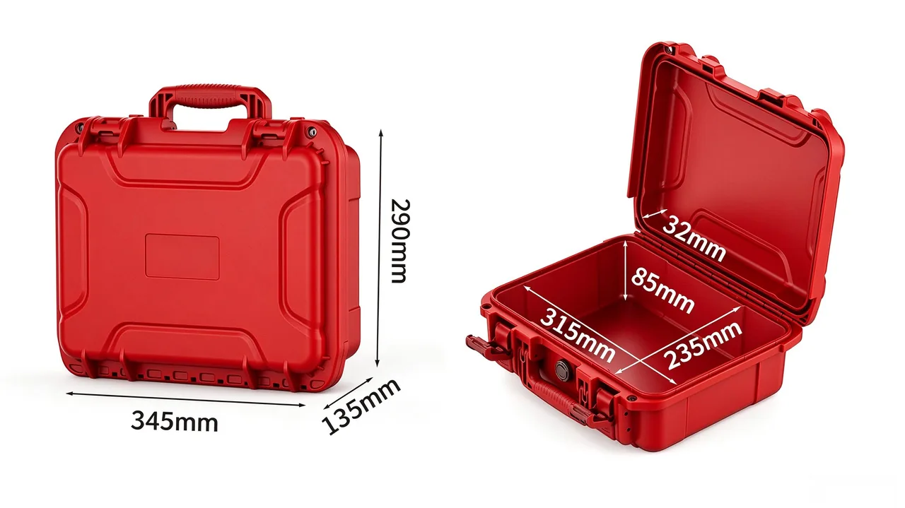
A geological survey camp can sit hundreds of kilometres from the nearest paved road, and a single working day may move a field team from a humid river valley to a wind-scoured mountain pass. Survey instruments travel with that team, and every loading, unloading and shoulder carry places the outer case between the equipment and the surrounding environment. The case is often treated as an accessory, yet its specification decides how much dust reaches the cavity, how much vibration is absorbed before it reaches the contents, and how comfortably a crew member can carry the load uphill. This article looks only at the container: shell material, structural reinforcement, internal lining, dust sealing, shock isolation and carry hardware, together with the handling and transport rules that keep a case serviceable across a long field season. It is written for procurement staff and operations leads who must turn field conditions into verifiable requirements, and it deliberately avoids any discussion of what sits inside the packed item.
A field season rarely destroys a case in one dramatic event. Wear accumulates through small repeated actions: the lid dropped shut at dusk, a strap dragged across rock, a gasket clamped down while grit is sitting on the sealing face. Designing a survey case therefore means designing for repetition as much as for peak load. The sections that follow start from the working conditions that generate load, then move through material selection, structural detailing, lining and compartment layout, sealing and pressure control, cushioning, carry systems, vehicle securing, field maintenance and finally verification. Each stage can be tied to a requirement written into a tender document, which is the practical way to keep a specification meaningful once it leaves the design office.
Field Conditions That Shape the Case Specification
A field team's daily movement defines the loads a survey case has to survive, and three forms of exposure dominate in most geological work. The first is continuous dust, generated by unsealed access tracks, drilling activity and wind erosion of exposed ground. Such particles are small, cling to surfaces and settle into gaps, so once they enter a cavity they are difficult to remove without risking scratches. The second is combined vibration: a vehicle travelling over broken rock produces a long, low-amplitude shake, while a crew member crossing a gully or descending a slope produces short, high-amplitude knocks arriving from varying directions. The third is temperature cycling, the least visible of the three. Between a frosty dawn and a sunlit midday the air inside a well-sealed case expands and contracts, so the lid can feel sucked down when opened in the cold while the gasket carries extra shear in the process.
Translated into requirements, these conditions split into three groups. Environmental requirements cover dust ingress, weathering and resistance to ultraviolet exposure. Operational requirements cover how often the case is opened, whether the lid can be worked with one hand, the order in which contents are removed, and how firmly the interior holds each item. Transport requirements cover impact height, stacking load and the method used to secure the case in a vehicle. The three groups pull against each other. Thickening the shell to resist impact adds mass that a crew member must carry, while thinning the lining to save that mass reduces the cushioning available for the contents. A sensible selection process therefore starts by naming the dominant working condition, then trades between material, structure and lining instead of maximising a single number. The checklist approach used for field site case examples is a useful reference, because it maps conditions to structural features one by one rather than comparing finished cases on headline figures. Recording those assumptions before a tender is issued also makes later disputes easier to settle, since both parties can point to the same documented working conditions.
Shell Material and Wall Thickness Trade-Offs
Material choice sets the impact floor and the long-term weathering behaviour of a survey case. Most field specifications come down to a trade between engineering plastics and metals. Modified polypropylene offers good toughness, low density and chemical resistance, moulds with an even wall, and resists brittle fracture at low temperature. Aluminium brings high stiffness, fast heat conduction and dimensional stability, but it is heavier and needs surface treatment to resist moisture and salts. Composite panels sit between the two, with good rigidity but demanding edge finishing. Many survey organisations settle on modified polypropylene as the body material, using structural features to compensate for lower stiffness and spending the remaining mass budget on lining and carry hardware.
Thickness is not a simple case of more being better. Adding wall thickness raises bending stiffness, but it also increases total mass, extends cooling time during moulding and raises the risk of internal stress. A more efficient approach concentrates material along the load paths: a thicker base and corner region, moderate side walls supported by vertical ribs, and a widened lip around the opening that carries the gasket. For the same amount of material this usually performs better in drop and stacking tests than a uniform increase. Wall thickness and lining thickness are also coupled. The stiffer the shell, the more readily impact is transmitted through it toward the lining, which means the cushioning travel has to grow rather than shrink. A structured review of load paths and thickness allocation, such as the one set out for case shell design, gives both buyer and supplier a shared vocabulary when these trade-offs are discussed.
Surface treatment deserves equal attention in a weathering assessment. Under prolonged ultraviolet exposure, a case with an insufficient stabiliser package will chalk and fade; the immediate strength may be unchanged, but appearance and sealing-face condition deteriorate over the service life. Printed or hot-stamped markings should use wear-resistant ink and avoid areas that rub against handles or lashing straps. Metal components need anodising or coating to prevent moisture and salt from driving corrosion at threaded holes. Assessing these details alongside the base material prevents a case from being retired early simply because it has become hard to inspect and unpleasant to handle.
Ribs, Corners and Edge Reinforcement
Handling knocks are the most common source of damage to survey cases, and they concentrate at corners and bottom edges. Dragging during vehicle loading, tipping the case onto a rock slope, and sliding off a step all put concentrated stress on a corner. A mature corner design uses a thickened wrap or a separate corner guard to spread that stress into the two adjacent edges, so the corner point itself does not crack. Where the guard is replaceable, a damaged part can be swapped out without scrapping the whole case.
Rib layout follows the same directional logic. Vertical ribs mainly resist side-wall bending, while horizontal or circumferential ribs keep the cross-section from deforming under stack load. Where the two meet, a generous radius avoids flow hesitation during moulding and reduces stress concentration. The base usually needs several longitudinal beams that raise bending capability and provide a stable bearing plane for stacking. The overlap between lid and body is another area to watch, because it is a stiffness discontinuity; a number of failures occur at the rim near the hinge, which is why local reinforcement behind the hinge seat is common practice.
Structural reinforcement does not mean making every surface heavier. If overall stiffness becomes too high, more impact energy is passed on to the lining and the contents, increasing the burden on the cushioning design. The better balance is a shell that resists deformation while retaining some elastic travel. Stacking load paths and impact risk are worth reviewing on the same drawing, which is the approach described for stacking and corner structure in relation to protective case assembly.
Hinges and latches belong to the same structural discussion. Hinges should be wide and placed close to the ends of the opening so that opening torque is spread over a larger area instead of loading one side. Latches should be distributed evenly so gasket compression stays close to constant along the rim. When latches are clustered in the middle, the two ends of the opening can end up under-compressed and become the first route for dust. Adding a centre latch along a long edge is generally more effective than making existing latches heavier, and it keeps total mass under better control.
Foam Lining Density and Layering
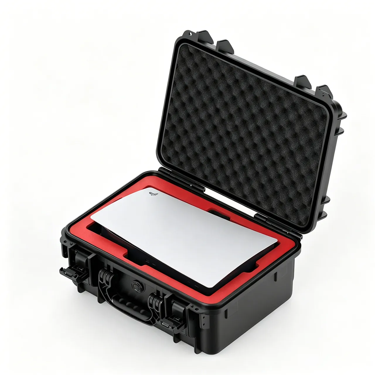
The lining absorbs more energy than the shell in most real impacts. Its performance depends on density, thickness and compression behaviour. A low-density foam rebounds quickly under hand pressure and damps small vibration well, but it can collapse in a single large impact; a high-density foam supports the contents and limits movement, yet transmits more of the shock to the item it is supposed to protect. Survey instruments are often irregular in shape with concentrated mass, so one uniform block rarely suits every position, and a layered build is the usual answer.
A practical layering sequence uses a medium-density foam against the shell to create a stable bearing plane, a lower-density foam against the instrument surface to damp higher-frequency vibration, and a local high-density insert around the centre of gravity to control movement of the heaviest part. Where an instrument has a fragile section, a separate cushion pocket keeps its compression travel independent of neighbouring parts. The foam should sit flush against the shell rather than bridging gaps, because a void allows the lining to migrate under repeated vibration, silently changing the protection boundary. Further detail on density grades and bonding methods appears in the guidance on foam lining selection.
Cell structure matters as well. Closed-cell foam takes on little water and does not readily trap dust, which suits dusty survey areas; open-cell foam breathes better, but once it absorbs moisture it dries slowly and can develop odour while its dimensions shift. Whichever structure is chosen, the material should be confirmed as non-brittle at low temperature and as retaining a reasonable proportion of its rebound after repeated compression. Compression set data from the supplier gives an objective basis for comparing two otherwise similar proposals.
Compartments and Movement Limitation Inside the Case
Compartment layout gives every item a defined place. A survey crew normally carries an instrument body, cables, mounts and a notebook together, and if all of them share one cavity the cables will tap against the instrument as the case moves, eventually leaving marks on coatings or windows. A better arrangement divides the interior by frequency of use and mass distribution: the main unit gets a central position with foam contact, cables and accessories sit in a side compartment with some freedom to move, and crush-sensitive parts are placed close to a rigid boundary so the shell helps carry the load.
The goal of retention is not to clamp contents tightly but to limit how far they can travel. Excessive clamping raises local contact stress and produces dents at point contacts. Common techniques include local bosses, pre-cut slots and a layered pressure plate. Pre-cut foam follows the outline of the instrument so an even clearance remains on all sides, filled by the natural rebound of the material; the layered plate adds mild preload once the lid closes, keeping items from shifting while the case is shut. Centre of gravity also affects carrying stability, and it is generally better to place the heaviest part slightly below the middle of the case. Compartment fit for optical and precision equipment is explored further in the notes on optical instrument compartment fit.
When the contents change frequently, removable dividers or modular trays are worth considering. Dividers located by slots can be rearranged without new tooling, which suits survey tasks that swap instrument combinations between phases. Modular trays hold a standard accessory set together so it can be lifted out and counted before departure, reducing the chance that something is left behind. Any removable part needs a retention feature, otherwise it can work loose over rough ground and strike the instrument, becoming a new source of damage rather than a control.
Gasket and Sealing Face Design Against Dust
Dust generally reaches a cavity by three routes: the lid-to-body overlap, the mounting holes for latches and hinges, and the equalisation passage that allows the case to open and close smoothly. The overlap is the dominant route, and it is where the gasket does its work. Gasket performance is set by material, cross-section and compression, and a poor match in any one of those variables undermines the other two.
On material, silicone keeps its rebound at low temperature, which suits mountain and plateau work with wide day-night swings. EPDM resists ageing and ozone better, staying flexible through long outdoor exposure, though its low-temperature rebound is weaker. On cross-section, a solid round cord is simple and compresses evenly on a flat mating surface, while a lipped profile blocks flow at low compression and suits cases whose lid is less rigid. Compression is normally held between roughly one fifth and one third of section height; too little leaves a gap, too much accelerates permanent set. Groove width and depth must match the cord, and corners should use a moulded or continuous joint rather than a spliced straight run. The relationship between profile and groove is described in more detail under gasket and groove fit.
Sealing also depends on the flatness of the mating faces and the distribution of clamping force. A warped rim will leave a local gap no matter how well the cord is specified. First-article measurement of flatness, followed by a feeler-gauge check of the closed joint during assembly, catches this early. Latch count and spacing must suit the length of the case: too few latches along a long edge leave the middle of the gasket under-compressed, and that is one of the most common reasons a field case starts letting dust in after a season of use.
Turning Dust and Water Ratings Into a Specification
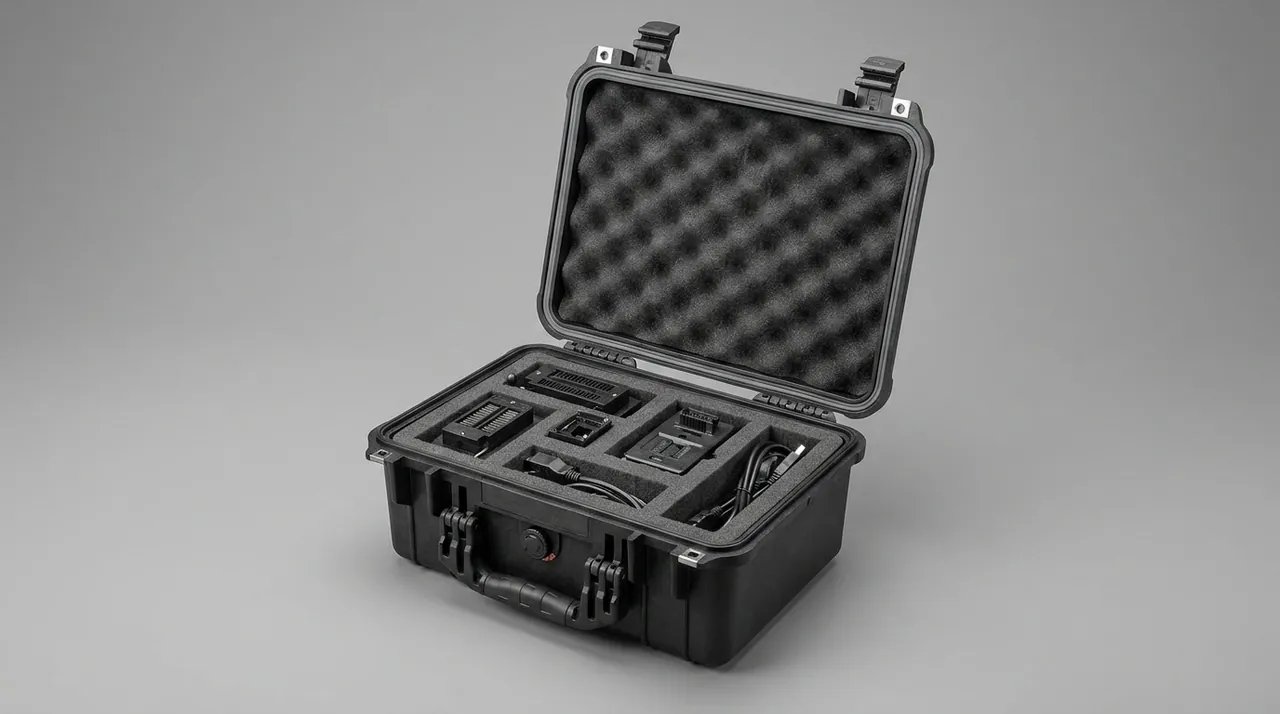
Dust and water protection are usually quoted together, yet the two media behave differently. Dust is a solid particle, so its entry depends on gap dimensions and the tortuosity of the air path. Water is a fluid, so its entry depends on surface tension, pressure difference and hydrostatic head. In geological work, dust appears far more often than standing water, which argues for treating particle protection as the primary requirement and then deciding on liquid protection according to whether the crew works in rain or crosses water while carrying the case.
Quantitatively, the industry uses a two-digit protection code: the first digit covers solid particles, the second covers liquids. A higher number is not automatically better for field use, because demanding liquid protection generally requires tighter sealing, which reduces ventilation and makes the case harder to open and close, and can also increase the pressure difference inside the cavity as temperature changes. For dry, dusty survey work, full particle protection covers most needs. Where short rain showers or vehicle fording are expected, the assessment should extend to whether the liquid rating needs to rise, along with the clamping force of the gasket and the number of latches. The correspondence between grading and test conditions is set out in the dust and water rating guide, and the agreed judgement method belongs in the technical annex so that a single digit cannot be read two different ways.
A frequent misreading treats the digit as the only criterion and ignores the test conditions. The same rating does not mean the same result across different particle size distributions or exposure durations, and in service a case also accumulates opening wear and thermal cycling, so protection degrades slowly with time. A technical agreement should therefore state sampling proportion, failure criteria and re-check intervals alongside the target rating, turning the number into a verifiable commitment rather than a mark printed on the packaging.
Pressure Equalisation and Condensation Control
A well-sealed case runs into a problem that is easy to overlook: the air inside expands and contracts with temperature, creating a pressure difference across the shell. On a cold morning the internal pressure drops, the lid is held more firmly, and opening requires extra force while the gasket experiences shear. As the day warms, internal pressure rises, and if clamping force is marginal the air bleeds slowly through the joint, drawing dust into the gap on its way out. This slow breathing effect is pronounced where day-night temperature differences are large.
The usual answer is a controlled vent path, commonly called pressure equalisation. Its purpose is not to let air move freely but to allow gradual gas exchange while blocking particles and droplets. A common arrangement places a breathable membrane on the inside of the port and a protective cap or labyrinth channel on the outside, so air must change direction several times before reaching the cavity. Selection should consider whether membrane airflow and particle retention match the site, and whether the membrane tolerates low temperature and ultraviolet exposure. In areas with very fine, long-suspended dust, placing the port on the side rather than the lid reduces accumulation. The underlying principles are covered under temperature and pressure control.
Moisture control and pressure equalisation are best considered together. Water vapour inside the cavity arrives both from outside and with the air trapped at packing time. For shipments that stay closed for long periods, a modest desiccant charge combined with low vapour transmission through the vent slows external ingress. Where condensation is suspected, opening the case after a task and inspecting the lining for water marks is a quick check, with attention on the layer closest to the shell, since the largest temperature gradient usually produces the first condensation there.
Cushioning Layers and Impact Energy Absorption
Vibration control and impact resistance are related but not identical design goals. Vibration is a long, low-amplitude reciprocating load that tests the fatigue behaviour of the lining; impact is a short, high-amplitude energy input that tests whether the combined compression travel of shell and lining is sufficient. Both occur in field survey work, so the lining has to balance rebound against energy absorption rather than optimising one alone.
From an energy standpoint, a drop first deforms the shell elastically and absorbs part of the input; the remainder is consumed by the lining as it compresses and rebounds. A thicker lining with more travel lowers the acceleration peak passed to the instrument, but it reduces usable internal volume and increases the size and mass of the case. Variable thickness is a common compromise: a deeper cushion near the centre of gravity of the instrument and a thinner layer at the edges, putting material where the risk is highest. The cushioning at the four corners and along the base should be continuous, so no hard point is left exposed. Judging whether the design works requires impact data rather than a hand-press test, and the drop heights and attitudes used in verification are discussed under drop impact verification.
For instruments with uneven mass distribution, local support is worth adding: a support point near the centre of gravity lets impact force travel to the base along the shortest path instead of passing through slender sections. There should be compressible space between the lining and the base, because a lining already fully compressed during assembly has no travel left when impact arrives. Where a physical drop test is possible, the resulting acceleration curve indicates whether cushion thickness still needs adjustment.
Carry Systems: Handles, Straps and Back Contact
A survey case is ultimately carried by a person, so the carry system directly affects both the crew member's endurance and the service life of the case. The handle is the most basic part, and its mounting points must land on stiff regions, normally aligned with vertical ribs or internal reinforcement bosses, so that no isolated load point forms on the shell. The connection between handle and case should be replaceable, because field damage cannot be repaired by welding or moulding on site.
Shoulder straps and back contact convert a single-point grip into a distributed load. A sound arrangement brings the straps into contact with the back face of the case and uses a waist pad to transfer part of the weight to the hips, reducing pressure on the shoulders. If the back face is a flat plane, long carries tend to swing, which can be improved with a back pad or shallow recesses. For heavier cases, a wheel and telescopic handle combination deserves evaluation for moving across hard ground or within a camp. Any added carry accessory changes the centre of gravity and adds mass, so the accessory should be counted in the total weight when a case is selected. Load paths in handles and straps are considered further under ground handling and carry.
Centre of gravity also shapes carrying posture. When a case is carried on its side, the strap force and the long axis no longer lie on the same line, and walking generates a twisting moment that makes the carrier adjust position repeatedly. In backpack mode the long edge is therefore normally kept vertical, with the heavier side closer to the body. Wheels suit hard surfaces around a camp, but on gravel, sand or steep ground they add burden instead of removing it, so the mix of terrain should be settled before deciding whether to include them.
Securing the Case During Vehicle Transport
Once loaded into a vehicle, a case faces a different mechanical environment. Floor vibration, longitudinal inertia during braking and the static load of stacked cases all act continuously during transit. If the case is free to slide, repeated collisions will damage corners and latches first, which makes the securing method and the transport marking equally important.
Common securing practice combines base slots or rails that engage the vehicle floor, lashing straps around the waist of the case, and separation material between adjacent cases. Stacking follows the principle of heavy below and light above, with bearing faces of upper and lower cases aligned flat so nothing is left unsupported. For long road movements, a small buffer gap in the cargo bay allows the case some travel under braking instead of transferring the whole load into the straps. Latches should never be treated as the primary restraint: their job is to hold the lid closed, while lashing and rails carry transport loads. Marking should state centre of gravity, maximum stack height and moisture precautions so that loading staff can judge handling without opening anything. Layout conventions for such marking are described under transport marking layout.
Temperature and humidity changes during transit also deserve attention. A day-night cycle in the cargo bay can produce condensation on the outside of the case, and if the pressure difference is not equalised in time, moisture may creep along the joint. For loads sensitive to humidity, keeping the cargo space ventilated or leaving air channels between cases reduces local moisture build-up. Photographing the load after it is secured provides a reference for comparing condition on arrival.

Field Maintenance and Seal Replacement
Maintenance resources in the field are limited, so the reliability of a survey case depends heavily on whether wear parts can be replaced without special tools. The gasket deserves the most regular attention. After prolonged compression it takes a permanent set, and particles embedded in its surface are rolled into scratches that eventually leave a leak path across the joint. A visual check before every long deployment, looking for flattening, cracking or local separation, is a simple and effective routine.
When replacing a gasket, clear old adhesive residue and dust from the groove first, then seat the new cord at the original cross-section rather than forcing in a larger profile, which raises closing force and accelerates latch fatigue. Latch and hinge pivots benefit from a small amount of lubricant rated for low temperature; thick grease should be avoided because it hardens in the cold and collects dust. Cleaning is best done with a soft cloth and water, avoiding a high-pressure jet aimed directly at the gasket or the vent structure. For long storage the gasket should be left relaxed, and the latches should not be held at maximum compression for months on end. Replacement intervals and rejection criteria are set out under gasket replacement points.
A simple spare-parts and record routine helps as well: a spare gasket, spare latches, a few fasteners, and a card recording opening counts and maintenance actions. Gasket ageing tracks opening frequency, dust concentration and sun exposure, so records allow replacement to be scheduled by actual use intensity rather than by calendar year. When local deformation appears, the first question should be whether it came from assembly or from material ageing, since only the second calls for a full replacement.
Verification, Acceptance and the Compliance Boundary
Pre-production verification and goods-in acceptance are the final gate between design intent and physical product. Verification normally covers three families of tests. Vibration testing examines the stability of structure and lining under long, repeated loading. Drop testing examines cushioning behaviour under short, high-amplitude impact. Sealing and dust testing examines how well particles and moisture are excluded under sustained exposure. The order and severity of these tests should follow the dominant working condition rather than a single default setting. Acceptance can then begin with visual and dimensional sampling, covering rim flatness, continuous gasket contact after closing, and the absence of gaps between lining and shell.
To be explicit about scope: this article deals only with the outer container used for carrying and protection, comprising shell, lining, sealing and carry structure. It does not address the properties or purpose of any packed item, and it makes no judgement about whether the contents of a case are compliant. Where survey equipment crosses a border or is exported, whether it falls under control, and which procedures apply, must be assessed by the party responsible in light of local law and export control rules, with any licence obtained before shipment. Nothing here constitutes a compliance conclusion. Scenario-based settings for transport vibration testing are discussed under vibration test verification.
Batch consistency also belongs in acceptance. After first-article approval, sampled checks of rim flatness, gasket contact and lining dimensions during series delivery keep later units aligned with the approved sample. Where the user has explicit dust requirements, the agreement can state how re-testing is carried out after delivery and how non-conforming lots are handled, which reduces later disagreement. Once acceptance is complete, filing case identifiers, delivery batch and inspection results together makes any future problem traceable.
Frequently Asked Questions
Q: Why is dust protection placed ahead of water protection in a geological survey case?
A: Because dust exposure happens far more often than immersion in most survey work. Unsealed tracks, drilling activity and wind-eroded ground generate fine particles continuously, and once those particles enter the cavity through the lid joint they settle around instrument seams and scale markings, where removal is slow and risks secondary scratching. Standing water, by contrast, is an occasional event rather than a daily one. Treating particle protection as the baseline requirement and then deciding separately whether the liquid rating must rise fits the rhythm of field use more closely. Settling the dominant working condition first, and locking the priority order, gives sealing design and goods-in inspection a clear basis. It also prevents paying for a liquid capability the crew rarely needs in the form of extra mass, stiffer latches and a harder-to-open lid. Where a crew works through a wet season, the priority order can be revisited, but the starting point remains the medium that appears most often.
Q: Does softer foam always mean better vibration isolation?
A: No. A soft foam rebounds quickly and damps small vibration well, but in a large drop it can collapse in one pass, and once its compression travel is used up the remaining shock still reaches the instrument. Soft foam also holds contents less firmly, so items shift inside the cavity after repeated handling. A more reliable approach layers the lining by position: medium density against the shell for a stable bearing plane, lower density against the instrument surface for vibration damping, and a local high-density insert around the centre of gravity to limit movement. Judging whether a lining is suitable should combine acceleration data from impact testing with the practical experience of loading and unloading the case. A single uniform block of one density should not be expected to carry the whole isolation task, and a hand-press impression of softness is not a measurement. The useful check is to compare two candidate linings using the same impact drop and the same load, since only then do the differences in rebound and in compression travel become visible.
Q: How often should the gasket be inspected when a case is opened frequently in the field?
A: Base the interval on task cycles rather than a fixed calendar. A visual check before every long deployment, and again after each transport task, covers most needs: look for flattening, cracking, local separation and grit pressed into the surface. Where the working area has heavy dust, the checks should be more frequent. Whether a gasket has failed can be judged by observing whether contact along the rim stays continuous after closing and whether the suction felt on opening has weakened noticeably. Replacement should follow the original cross-section, with residue and dust cleared from the groove first. Forcing in a larger profile is a common mistake, because it raises closing effort and speeds up latch fatigue without improving the seal. Keeping a simple log of opening counts and cleaning actions also helps, since it turns a calendar guess into a replacement decision based on actual use. Where a case is opened many times a day, a check before each deployment and after each transport task is a reasonable minimum.
Q: Does a thicker case wall give better protection for the instruments?
A: Wall thickness raises bending stiffness, but protection does not increase in a straight line with it. An overly thick wall adds mass that the crew has to carry, and it can make the shell so stiff that impact energy is transmitted more directly into the lining and from there into the instrument. A more efficient strategy concentrates material along the load paths, thickening the base, the corners and the rim lip while keeping side walls moderate and supporting them with vertical ribs. For the same material budget this usually gives a better result in drop and stacking tests. Wall thickness and lining thickness are coupled as well: the stiffer the shell, the more cushioning travel is needed to compensate, which is why the two dimensions should be evaluated together rather than adjusted one at a time. The practical question is whether the case can absorb the expected drop without passing a damaging acceleration peak to the contents, and that outcome depends on cushion travel as much as on wall gauge.
Q: Does a survey case need a pressure equalisation structure?
A: In areas with pronounced temperature differences it is usually worth including. When the air inside a well-sealed case expands and contracts, a pressure difference builds across the shell. That difference makes the lid harder to open and applies shear to the gasket during the pull, which over many cycles can accelerate ageing. A controlled vent path allows gradual gas exchange while blocking particles and droplets, so the pressure difference stays modest without opening the cavity to dust. The decision depends on day-night temperature swing, how the crew enters and leaves the site, and how long the case stays closed. Where the case is routinely opened in the cold early morning, or moves repeatedly between warm and cold zones, the benefit is clearer. Mounting the port on the side rather than the top reduces dust accumulation. In dry and thermally stable conditions with frequent opening, a simple vented plug may be sufficient, while a large day-night swing usually justifies a full membrane assembly with a labyrinth cap.
Q: What extra demands does a backpack-style carry system place on the case structure?
A: Backpack carrying spreads load from a single grip to the shoulders, back and hips, which changes where the case feels force. Strap anchors must land on stiff regions, normally aligned with internal reinforcement bosses or vertical ribs, because an isolated load point on the shell can develop cracks over time. The back face needs to contact the pad properly to limit swinging; a completely flat back face tends to rock during long carries and wears the straps faster. Accessories also add mass and shift the centre of gravity, so they should be counted in the total weight during selection. The practical check is to load a real case and carry it, confirming where the force lands, rather than judging the layout from a drawing. It is also worth checking that the strap hardware cannot catch on rock, since a snagged strap applies a sharp load to the anchor instead of a smooth one, and replacing frayed straps early is far cheaper than repairing a cracked anchor.
Q: How can a buyer judge whether a supplier's dust rating is credible?
A: Cross-check in three directions. First, ask for the test conditions behind the claimed rating, including particle type, concentration, exposure duration and pass criteria, rather than a bare number. Second, verify that the sealing structure matches that claim, for example whether the rim groove suits the gasket profile and whether the latch count can apply even clamping force along the rim. Third, review the batch consistency arrangements, including incoming inspection of the gasket and sampling rules for finished cases. If a supplier cannot describe how the result was judged, the rating carries little practical weight. A buyer can also convert the operating conditions that matter most into acceptance clauses, so that the claim is tested against the way the case will actually be used. A short factory visit, or a review of incoming inspection records, often reveals more than a certificate on its own, because it shows whether sealing parts are controlled in routine production. Asking a supplier to explain one rejected sample can also indicate how well the process is understood.
Q: How should a survey case be secured during vehicle transport?
A: Start by engaging the base slots or rails with the vehicle floor, then apply lashing straps around the waist of the case, adding separation material between adjacent cases where needed. Stacking follows heavy below and light above, with bearing faces aligned flat so nothing is left unsupported. The main risk to avoid is treating the latches as the primary restraint; their role is to hold the lid closed, while transport loads belong to the straps and rails. For long road movements a small buffer gap in the cargo bay lets the case travel slightly under braking instead of passing the entire load into the straps. Marking centre of gravity and maximum stack height clearly helps loading staff make the right call without opening anything. It is also worth confirming that the rails or slots carry the stack load rather than the case walls alone, and that stack height stays within the marked limit for the whole journey. Checking the arrangement after the first few kilometres of travel catches settling early, while the load can still be corrected easily.
Q: Does carrying survey equipment raise export control questions?
A: Whether equipment falls under control depends on its specific type, technical parameters, destination and end use, and that assessment has to be made item by item by the party responsible, in light of local law and export control rules. This article discusses only the outer container, covering shell, lining, sealing and carry structure; it says nothing about the properties or purposes of packed items and makes no judgement on whether contents are compliant. Before any cross-border movement, the classification and licence assessment should be completed by the function that owns that responsibility, confirming which documents and declarations are required, and only then should packing and transport be planned. Container performance and the compliance status of the contents are two separate questions and should not be substituted for one another. Documenting the classification decision and keeping it with the shipping papers helps if a carrier or customs authority later asks for the basis of the assessment, and an internal review by the responsible function clarifies which party carries the duty to obtain any licence.