

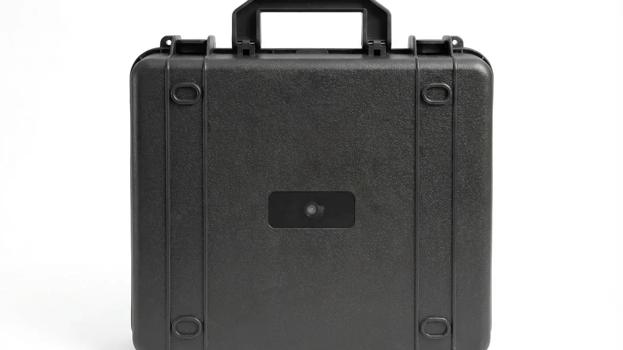
An industrial CT system that resolves features of a few micrometres at factory acceptance will still face dozens of random vibration events above 2 g, several package drops peaking beyond 15 g, and repeated condensation cycles on a single interprovincial road trip. The two costliest components inside the machine are also the two least able to absorb those loads: a microfocus X-ray source is a vacuum-sealed high-voltage device, while a flat panel detector is a large, very thin glass substrate. Both can measure micrometres, yet both are defeated by a millimetre of misalignment or a single hard impact.
The JUNZHIJIA protection principle is to treat the X-ray source, the flat panel detector, the gantry motion axes and the peripheral electronics as four separate load domains, constrain each one on its own terms, then lock their relative positions with a single rigid shell so transport energy travels through the case structure instead of the equipment. This article works through that principle, covering design parameters, material choices, test baselines and acceptance criteria for road, rail, sea and air freight.
Table of Contents
- Transport Risk Profile of Industrial CT Equipment
- Sensitivity of the Microfocus X-ray Source and How to Constrain It
- Brittle Protection and Thermal Stability of Flat Panel Detectors
- Locking the Gantry, Rotation Stage and Motion Axes
- Preserving Geometric Alignment and Calibration State in Transit
- Temperature Stability and Thermal Drift Control
- Humidity, Cleanliness and IP Sealing Selection
- Case Materials and Structure: Rotomoulding, Injection Moulding and Aluminium Frames
- Liners and Foams: Layered EPE, EVA and IXPE Cushion Design
- Choosing Impact and Vibration Test Baselines
- Stacking, Rigging and Handling Practice
- Industrial CT Case Selection Parameter Comparison
- Arrival Acceptance Criteria and Unpacking Sequence
- Frequently Asked Questions FAQ
- Conclusion and Related Reading
Transport Risk Profile of Industrial CT Equipment
Industrial CT systems appear as benchtop microfocus units, vertical rotation-stage machines and large horizontal or inline scanners. All of them depend on a source-to-detector path that must hold its geometry, because the source-to-object and source-to-detector distances set the magnification and therefore the resolution. Any relative movement in transit forces a fresh geometric calibration on site, and in severe cases the machine will not pass a standard-sample acceptance test.
Four load types overlap. The first is mechanical shock: forklift set-down, load shift inside a trailer and the moment a sling goes slack all produce accelerations far above the equipment's own weight, and for a system above 300 kg a 300 mm drop generates local loads of several thousand newtons at a case corner.
The second is random vibration and resonance. A highway spectrum carries energy across roughly 3 to 200 Hz, and a cantilever such as a detector slide whose natural frequency falls in that band will see vibration amplified several times over, with damage accumulating as fatigue rather than as a single fracture.
The third is temperature and humidity cycling. A sea container can swing more than 25 degrees Celsius between day and night, and moisture in the trapped air crosses the dew point as the temperature falls, depositing condensate on detector surfaces and threaded fasteners, which invites flashover and corrosion.
The fourth is particulate contamination, because beryllium windows and scintillator coatings are extremely particle sensitive and debris from the packaging material becomes a contamination source.
| Failure mode | Physical mechanism | Consequence | Primary countermeasure |
|---|---|---|---|
| --- | --- | --- | --- |
| Focal spot drift | Cathode shifts relative to target after impact | Resolution loss, blurred images | Damped cushion plus hard travel stop |
| Beryllium window crack | Local impact, particulate adhesion | Vacuum leak, no beam output | Isolated cavity, clean liner, dust cap |
| Detector panel fracture | Glass substrate bent beyond allowable deflection | Dead pixels, scrap panel | Full-area support, low density foam |
| Detector gain drift | Temperature gradient changes array response | Non-uniform grey levels, artefacts | Controlled temperature, arrival soak |
| Geometric misalignment | Frame and stage move relative to each other | Magnification error, recalibration | Dowel pins, locking blocks, rigid base |
| Motion axis brinelling | Vibration dents the ball raceway | Audible noise, lost accuracy | Axis lock plus isolation pads |
| Metal corrosion | Condensate and salt spray acting together | Seized threads, cosmetic failure | Desiccant, pressure valve, coating |
Sensitivity of the Microfocus X-ray Source and How to Constrain It
A microfocus X-ray source is built from three parts: the vacuum tube body, the high-voltage generator and the cooling circuit. Their ability to survive transport differs sharply, so they must be handled separately.
The tube body is the weakest link. Focal spot size is typically between 5 and 50 micrometres, and the relative position of filament, focusing cup and target is measured in the same units. The interior is under high vacuum while the exterior sees atmospheric pressure, so the envelope is itself a pressure vessel. Under axial impact the envelope deforms, the internal electrodes shift, and the result is a larger focal spot and softer images once the beam returns. The right architecture combines damped cushioning with a hard travel stop: a medium density EVA or polyurethane foam wraps the tube and absorbs energy across a 10 to 30 mm compression stroke, while a structural stop block limits peak displacement to within 2 mm. Cushioning alone lets energy pass straight through once the foam densifies, and a stop alone transmits the full acceleration into a small contact area.
The generator and its high-voltage cable form a difficult pair of weight and flexibility. A high-voltage tank often accounts for more than 60 percent of the source assembly mass, yet its cable must respect a minimum bend radius. Seat the generator on a base saddle, restrain it with a secondary strap, and coil the cable along its natural lay secured with hook-and-loop tape, keeping the bend radius at least five times the cable outside diameter.
The cooling circuit must be drained or sealed off. Check an oil-cooled source for leaks and plug the ports; for water-cooled models, drain and purge with dry air to avoid freeze cracking. The beryllium window needs its own protection too: at 0.2 to 1 mm thick it has almost no structural strength, so fit the original cap, avoid paper or open-cell sponge in contact, and record the window orientation so the assembly is never inverted.
Source performance is sensitive enough that this stage deserves precision-instrument protection levels. Related practice appears in Industrial X-ray Inspection Case Packaging and Cushioning Liners for Non-Destructive Testing Equipment.
Brittle Protection and Thermal Stability of Flat Panel Detectors
The flat panel detector is the largest and thinnest precision assembly in an industrial CT system. A typical design builds an amorphous silicon thin-film transistor array on a glass substrate, deposits a caesium iodide or gadolinium oxysulphide scintillator on top, and seals the stack inside a housing, so the panel behaves like a sheet of imaging glass whose sensitivity to bending, impact, temperature and humidity far exceeds that of ordinary electronics.
Bending is the primary enemy. On a large panel, say 43 cm by 43 cm, four-point support alone produces visible deflection under its own weight, and a concentrated transport load can initiate micro-cracks that emerge as clusters of dead pixels after installation. Prevention requires full-area support: a low density, low resilience foam such as 25 to 35 kg per cubic metre EVA or IXPE should carry the panel across its whole back face so the load spreads evenly, and edge-only support must never be used. Panel orientation and stacking direction also have to be locked, because the panel is most vulnerable to flexure along its normal axis, so the case should enforce a defined flat orientation and a divider that prevents in-plane sliding.
Temperature affects the detector in two directions. In cold conditions the thermal expansion mismatch between scintillator and encapsulant can micro-crack the coating, while heat raises dark current and the noise floor, so keep the case interior within roughly minus 10 to plus 45 degrees Celsius, place a temperature logger inside for long routes, and let the unit soak for four to eight hours after arrival before powering it. Most detector housings meet IP54 to IP65, meaning splash rather than immersion, so sea and tropical routes depend on desiccant holding relative humidity below 40 percent.
| Sensitive parameter | Reference limit | Effect of exceedance | Design response |
|---|---|---|---|
| --- | --- | --- | --- |
| Static bending deflection | Not more than 0.05 percent of long edge | Micro-cracks, dead pixels | Full-area foam support, no point loading |
| Impact acceleration | Not more than 15 g over 6 ms | Substrate fracture, delamination | 20 to 40 mm low density foam cushion |
| Operating temperature | 10 to 35 degrees Celsius | Gain drift, rising dark current | Insulation layer, post-arrival soak |
| Storage humidity | Not more than 60 percent RH | Electrode corrosion, hydration | Desiccant plus humidity indicator card |
Locking the Gantry, Rotation Stage and Motion Axes
The gantry and rotation stage move the source and detector relative to each other. They are the stiffest part of the system and also the part most easily loosened in transit, because the problem is not component strength but fretting wear inside precision kinematic pairs that vibrate at small amplitude.
Ball screws and linear guides suffer false brinelling. When transport vibration drives the balls a few micrometres back and forth, the oil film is squeezed out of the contact zone and shallow dents form, so the axis sounds rough and loses repeatability. Three countermeasures matter: lock the axes before shipment using mechanical locks or brakes; leave a protective oil film on screws and rails; and fit isolation pads between the case and the vehicle floor to attenuate high-frequency energy.
A rotation stage needs its angular contact bearings held in preload. Runout on a precision stage is often specified below 5 micrometres, and if transport shock releases the preload the bearing set has to be readjusted or replaced on site, so a dedicated transit locking ring that rigidly ties the stage to its base moves the bearings from a load-carrying state into a protected one.
Sensors and linear scales are silent victims. A scale read head rides tens of micrometres from its track, so vibration can shift the head or bow the scale, and the transit lock should therefore secure the read-head bracket. Cable carriers and air lines are easy to overlook as well, because an unrestrained energy chain swings inside the case and works the cables, so tie both ends to the frame so no free length remains. The logic mirrors precision metrology practice, discussed in Selection Guide for Precision Instrument Cases and Vibration-Safe Transport for Machine Vision Cameras.
Preserving Geometric Alignment and Calibration State in Transit
Every core parameter of an industrial CT system, including magnification, voxel size and geometric distortion, follows from the spatial relationship between the focal spot, the rotation axis and the detector plane. That relationship is established at the factory on a ball plate or line-pair target, and transport protection aims to bring the machine to site in a state that needs only a quick verification rather than a full recalibration.
Dowel pins are the first choice for holding geometry. Fitting tapered or cylindrical pins between the source bracket, the detector bracket and the base makes the three parts return to the same position on assembly, with repeatability down to about 0.01 mm, and the layout should follow the one-face-two-pin rule: a main pin that blocks translation plus a diamond pin that blocks rotation, which avoids over-constraint. Transit locking blocks should lock geometry first and load path second, making source and detector a rigid body in the transport attitude rather than leaving each wrapped in foam; the block needs enough second moment of area, and its bolts should be fully torqued and marked.
Saving the calibration data matters as much as the mechanical hold. A document pocket inside the case should carry the factory calibration report, the geometric parameter file, the standard-sample test record and a post-transport verification checklist covering ball-plate re-measurement, ball-centre distance deviation, voxel size deviation and grey-level uniformity. Only when data and hardware travel together can a field engineer decide quickly whether recalibration is required. The transport attitude must also have a single solution, because an inverted case puts the load through a completely different path. The approach in Transport and Storage of Metrology Standards offers a useful parallel.
Temperature Stability and Thermal Drift Control
The higher the resolution of an industrial CT system, the more temperature matters. The focal spot of a microfocus source drifts with thermal expansion of the tube body, detector dark current and gain shift with temperature, and thermal distortion of the gantry changes the source-to-object and source-to-detector distances directly. Temperature control is therefore an accuracy issue, not a comfort issue.
A high precision CT room is usually held at 20 plus or minus 1 degree Celsius with hourly excursions under half a degree. Transport cannot reproduce that, but it can avoid extremes, with a recommended range of minus 10 to plus 45 degrees Celsius, and slow the rate of change, because an insulated case shell makes the interior lag the ambient by several hours and that lag alone shaves off most of a temperature step.
Recovery time from thermal drift belongs in the acceptance plan. After a cold journey into a warm workshop the parts do not reach equilibrium together, because the metal frame and the composite detector housing have different thermal time constants, so measuring immediately gives an inflated error; practice is to soak for 8 to 24 hours before a first-article test and to record the soak duration. An in-transit temperature record also settles questions of responsibility: place a logger inside the case, sampling every 5 to 10 minutes across a minus 30 to plus 60 degree range, so the data shows whether limits were exceeded and separates the transport segment from on-site use. Cold environments need attention too, because a winter road freight or air cargo hold can fall below minus 20 degrees Celsius, at which point foam stiffens and cushion stroke shortens, so choose a material with a lower brittleness point or add cushion margin, as examined in Corrosion-Resistant Enclosures.
Humidity, Cleanliness and IP Sealing Selection
A higher ingress protection rating is not automatically better. What matters is whether the rating matches the real exposure, because excessive sealing creates a pressure problem while insufficient sealing lets moisture and dust through.
Select the IP rating from the exposure scenario, not from a desire to be safe. Under IEC 60529 and the equivalent national standard GB/T 4208, the first digit after IP denotes protection against solid objects and the second against water. In-plant movements and short road hops are covered by IP54 to IP55 against dust and splashing, open-air transfers and dock work call for IP65 or above, and only the possibility of brief immersion justifies IP67. Chasing IP67 regardless of context means a tight case developing a larger pressure differential, which fatigues seals faster and makes the case hard to open. A pressure equalisation valve is therefore necessary, because a fully sealed enclosure develops a real differential under air freight and day-night temperature swings, and the gasket then sits under a sustained one-way load that ages it quickly. A waterproof breathable valve lets gas exchange slowly while blocking liquid and particles, as set out in Pressure Equalisation Valves for Protective Cases.
Desiccant quantity should be calculated from cavity volume and journey length. Estimate the free air moisture plus the outgassing from liners and documents, add a safety factor for journey duration and seal leakage, then divide by the rated capacity of one bag and round up. Place a humidity indicator card inside and read it on arrival to decide whether a second drying cycle is needed, keeping desiccant in a breathable bag and never in contact with the equipment.
Cleanliness starts with the liner material: closed-cell foam and clean-grade film belong inside, while shedding open-cell sponge and untreated board do not, and the case should be cleaned and ionised before assembly so dust is not attracted to the interior.
| Exposure scenario | Suggested IP rating | Pressure valve | Desiccant level | Cleanliness need |
|---|---|---|---|---|
| --- | --- | --- | --- | --- |
| In-plant transfer, short road | IP54 to IP55 | Optional | Medium | Standard |
| Interprovincial road, rail | IP65 | Recommended | Medium-high | Elevated |
| Sea freight, tropical route | IP65 to IP66 | Required | High | High |
| Open-air transfer, dock | IP66 to IP67 | Required | High | High |
Case Materials and Structure: Rotomoulding, Injection Moulding and Aluminium Frames
The shell determines whether external loads bypass the equipment, so material choice balances stiffness, weight, weathering and cost rather than searching for the hardest plastic.
Rotomoulded LLDPE suits medium and large complete machines. Rotational moulding produces large, thick-walled shells in one piece with even wall thickness and no weld lines, plus good impact resistance and moulded exterior ribs. Its limitation is dimensional accuracy, which is looser than injection moulding, so it fits machines under roughly 500 kg where case tolerances are not critical, and linear low density polyethylene keeps better toughness at low temperature than homopolymer polypropylene, which helps for northern winter freight.
Injection moulded ABS and PC suit small to medium units in volume. Moulded parts hold tight tolerances, repeat well and finish cleanly, which supports snap-fit features and internal dividers. ABS balances stiffness and impact resistance, polycarbonate offers better toughness at higher cost, and a PC/ABS blend lands between them, so for portable or benchtop CT systems injection moulding is the better route.
An aluminium frame with composite panels suits heavy, high precision machines. Extruded aluminium has high specific stiffness, so it forms a wheeled platform that, with isolation pads and locking hardware, becomes a mobile transport fixture, letting the machine roll directly into the case without a second lift at the cost of higher price and dead weight.
Three structural points deserve emphasis. First, feet and top surfaces should have matching male and female features so stacking self-locates. Second, corners need independent reinforcement, because drop loads concentrate there. Third, the lid and body should have a positive hard stop so latches are never sheared under impact. Wall thickness for large shells typically runs 5 to 8 mm with ribs 8 to 15 mm high, but the actual values should be proven by drop and stacking tests rather than assumed, and equipment stored outdoors or near the coast also needs corrosion thinking throughout.

Liners and Foams: Layered EPE, EVA and IXPE Cushion Design
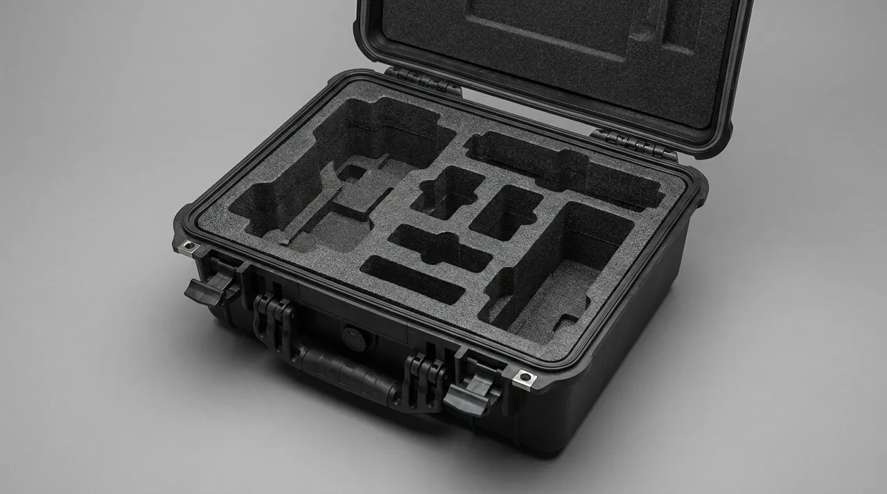
The liner is the only part of the case that touches the equipment, so its design decides whether impact load is flattened out; treating foam as gap filler is the most common conceptual error, because a liner is really a calculable energy absorption system.
The basic logic is to trade stroke for acceleration. If the permitted acceleration is a, the mass is m and the drop height is h, the required cushion stroke s follows roughly a equals 2gh divided by s, ignoring foam nonlinearity. As an example, a unit allowed 25 g dropped from 0.6 m needs about 47 mm of compression, while a 40 g allowance needs only about 29 mm, so cushion thickness must be derived backwards from the permitted acceleration rather than picked by habit.
Different foams do different jobs. Expanded polyethylene is resilient and inexpensive, so it works as the outer energy-absorbing layer. Ethylene vinyl acetate has tunable density and can be thermoformed into an accurate contoured cavity, making it the locating middle layer. Irradiation cross-linked polyethylene has fine closed cells and low compression set, so it belongs in direct contact with the equipment. Keep static compression between 25 and 40 percent: below that the foam cannot absorb enough energy, while above it the foam densifies quickly and impact is amplified rather than softened, so design for roughly 30 percent static compression and hold 10 to 15 percent stroke in reserve. Use thermoformed EVA liners for batch production and CNC cutting for prototypes, as detailed in The EVA Thermoformed Liner Process and Design Guide for Custom Foam Inserts.
| Foam type | Typical density (kg/m3) | Main function | Position | Note |
|---|---|---|---|---|
| --- | --- | --- | --- | --- |
| Expanded polyethylene | 20 to 30 | Outer energy absorption | Between shell and middle layer | Coarse surface, avoid contact |
| Ethylene vinyl acetate | 40 to 90 | Middle location, thermoformed | Main cavity body | Higher density is stiffer |
| Cross-linked polyethylene | 30 to 60 | Clean inner layer, antistatic | Direct equipment contact | Higher cost, cut cleanly |
| Polyurethane | 25 to 50 | High resilience, isolation | Under vibration-sensitive parts | Ages under long compression |
Choosing Impact and Vibration Test Baselines
Once the design is fixed it has to be proven. For high-value industrial CT equipment, testing is not a one-off certificate exercise; it is how design defects surface before shipment.
Drop testing verifies corner and base structure. Drop height follows the package mass class in the GB/T 4857 series, with heavier packages dropped from lower heights, and the sequence should cover the bottom corner, edge and face orientations. Afterward, check not only for shell cracking but also for liner displacement and movement of the equipment inside the case.
Random vibration testing verifies resonance avoidance. Choose the power spectral density for the intended mode, typically an ISTA series profile or an ASTM D4169 distribution cycle. The key question is not simply whether the package survives but whether an unexpected resonance peak appears, because a band with a strongly amplified response tells you the isolation design or structural stiffness needs revision, as analysed in Transport Vibration Testing and Resonance Avoidance and Full Case Vibration Test Procedures.
Stacking tests verify long-term storage and multi-layer loading. Apply a static load equal to the intended stacking tiers and hold it for the specified duration, then inspect for permanent shell deformation, latch distortion and liner collapse; on rotomoulded shells, stacking stability often becomes the bottleneck before impact resistance does. A low-pressure test for air freight then confirms that the sealed cavity and pressure valve work together, and damp heat and salt spray cover sea freight. A test report proves the design meets a defined baseline rather than promising survival on any real journey, so test conditions, sample state and pass criteria belong in the contract.
Stacking, Rigging and Handling Practice
Even a good design fails if handling is uncontrolled, so written practice removes human randomness.
Stacking must be forced by the shell geometry. A top locating recess and a matching bottom boss should be present so an upper case can only settle once aligned. Mark the maximum stacking tiers and single-unit mass on the side, and never exceed them; if extra tiers are unavoidable, put a load-bearing pallet between layers so the load goes to the floor rather than through the walls.
Rigging points must be obvious and usable. Large CT cases should have lifting eyes or sling slots at four corners with the centre of gravity marked, and a four-leg sling should keep the case level. Never lift from a single point, which tilts the load, because for equipment with precision kinematic pairs the tilt from poor rigging is as damaging as a drop. Forklift work has two hard rules: the forks must enter the pockets fully and stay level so they do not punch through the base, and travel and steering must be gentle with no hard braking, so reinforce the base around the fork pockets to take the concentrated load.
Securing the case in the vehicle is even more often neglected than packing. Strap or chock the case so it cannot slide during starts, stops and turns, and when several cases travel together put dividers between them, because rail freight adds longitudinal shunting loads and sea freight adds lateral roll inside the container.
Industrial CT Case Selection Parameter Comparison
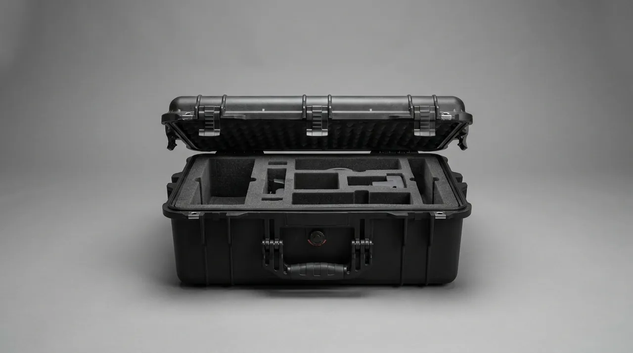
| Parameter | Small benchtop CT | Medium vertical CT | Large horizontal or inline CT |
|---|---|---|---|
| --- | --- | --- | --- |
| Equipment mass | 50 to 150 kg | 150 to 600 kg | 600 to 2000 kg |
| Shell process | Injection moulded ABS or PC | Rotomoulded LLDPE | Rotomoulded shell plus aluminium frame |
| Wall thickness and ribs | 4 to 6 mm and 6 to 10 mm | 6 to 8 mm and 8 to 15 mm | 8 to 10 mm and 12 to 20 mm |
| Total cushion thickness | 25 to 40 mm | 40 to 70 mm | 60 to 100 mm |
| Liner process | Thermoformed EVA | Layered EVA and IXPE | Contoured plus local suspension |
| Ingress protection | IP54 to IP65 | IP65 | IP65 to IP67 |
| Pressure valve | Optional | Recommended | Required |
| Mobility | Handle or pack style | Casters and tow handle | Casters, fork pockets and lifting points |
| Locking method | Latches plus liner interference | Latches plus dowel pins | Bolted locks plus transport fixture |
| Typical tests | Drop and vibration | Drop, vibration and stacking | Full suite plus low pressure and damp heat |
Arrival Acceptance Criteria and Unpacking Sequence
Arrival acceptance is the final link in the protection chain and the one most often compressed by schedule pressure. Split it into before, during and after unpacking, each with explicit criteria.
Criteria before unpacking. Verify the case exterior for dents, punctures and cracks, and check latches and hinges. Read the temperature logger to confirm the interior stayed within minus 10 to plus 45 degrees Celsius, read the humidity indicator card to confirm it has not reached the warning colour, and check seals and labels. Photograph any anomaly before continuing.
Criteria during unpacking. Remove restraints and liner in order, then check that transit lock blocks are present and tight, that foam is not crushed, cracked or displaced, that the equipment shows no impact marks, and that cables and connectors are undamaged and seated.
Criteria after unpacking. Let the equipment soak and then power it for a standard-sample test covering ball-centre distance deviation, voxel size, grey-level uniformity and signal-to-noise ratio, and compare the results with the factory report. Keep photographs, data and conclusions in the acceptance record for traceability.
Assign responsibility in advance, because protection duty is split between the packing party and the carrier, so the contract should state the evidence each must provide.
Frequently Asked Questions FAQ
Q: Should an industrial CT case be rotomoulded or injection moulded?
A: The choice follows equipment mass and production volume. Rotational moulding suits complete machines over roughly 150 kg with large outlines, because the shell forms in one piece with even wall thickness and no weld lines, creating a continuous load path through the corners and base, and it accepts thick walls with moulded exterior ribs for better drop tolerance. Injection moulding wins on dimensional accuracy and consistency, so it fits benchtop or portable CT units under 150 kg built in repeat batches, where latches, dividers and handles can be moulded in one shot for fast assembly. Remember that rotomoulded parts hold looser tolerances than moulded parts, so if the case must interface precisely with automated handling or racking, leave dimensional margin at the design stage. Low temperature toughness also differs between the two families, and linear low density polyethylene resists brittle cracking better, which matters for winter road and rail freight across northern regions where a warm workshop is many hours away.
Q: Why must a microfocus X-ray source have both cushioning and a hard travel stop?
A: Cushioning and a travel stop solve two different problems. Cushioning converts impact energy into heat through foam compression, which lowers the acceleration peak reaching the tube, but foam loses capacity as it compresses and once it densifies the remaining energy arrives as a hard collision. A travel stop adds a hard displacement limit, holding peak relative movement within about two millimetres so the tube cannot shift far even if the foam bottoms out. Cushioning without a stop lets shock pass straight through at the moment of densification, while a stop without cushioning transmits the full acceleration into a small contact patch and risks local stress concentration around the stop. Good practice wraps the tube in medium density foam across its whole circumference, pairs that with a stop block carrying its own cushion pad, and leaves a designed clearance between the block and the equipment so the stop only engages after the foam has already absorbed most of the incoming energy.
Q: If a flat panel detector shows dead pixels after transport, is transport always the cause?
A: Not always, but transport deserves priority in the investigation. Dead pixels arise from three sources: manufacturing defects, over-voltage or over-temperature in service, and micro-cracks in the glass substrate caused by transport impact. The way to separate them is to compare dark-field and bright-field images from the factory against those taken on arrival. Random point-like dead pixels that have not increased in number usually indicate a manufacturing defect, whereas a clustered or linear dead region points to crack propagation after mechanical loading. It is also worth reviewing how the panel was supported in transit, because point or edge support greatly magnifies the local bending moment and the risk of fracture. The practical safeguard is to agree an arrival retest method and tolerance in the contract and to write the panel support design into the packaging technical agreement, so responsibility can be established without argument if a dispute ever arises between the manufacturer, the packer and the carrier. Keep the support drawing inside the case file so the same fault is never repeated across shipments.
Q: How should desiccant quantity be calculated for sea freight of an industrial CT machine?
A: Work from cavity free air plus material outgassing, not from habit. First calculate the sealed cavity volume, look up the absolute moisture content of air at the highest expected temperature and relative humidity, and multiply to get the initial water load. Second estimate the equilibrium moisture held by liners, paper documents and wooden pallets from their mass and hygroscopic rate. Third apply a safety factor for journey duration and minor seal leakage. Divide the total water to be adsorbed by the rated capacity of a single desiccant bag, round up to the next whole bag and add a modest margin. In practice, place a humidity indicator card inside the case and read it on arrival to confirm relative humidity stayed below the warning threshold, then record the reading in the acceptance file as the basis for deciding whether a second drying cycle is needed and whether the seal performed as designed throughout the voyage. Retain that figure with the packing record so the next shipment can reuse it with confidence.
Q: Is a higher IP rating always better for an industrial CT protective case?
A: No, the rating should match the real exposure. A tighter seal means the case develops a larger internal-to-external pressure differential under air freight or day-night temperature swings, which puts sustained one-way stress on the gasket and ages it faster, and negative pressure can also make the case hard to open. Dust and splash protection is enough for in-plant transfers and short road journeys. Only open-air transfers, dock handling or possible brief immersion justify a higher water rating. Where a high sealing class is genuinely needed, pair it with a waterproof breathable pressure equalisation valve so gas can exchange slowly while liquid and particles cannot, keeping the differential within what the gasket tolerates. Higher ratings also demand tighter case geometry and better sealing surface machining, so cost rises noticeably. The sound method is to define the exposure first, derive the rating from it, and then verify the chosen class by testing. Document the class and the valve specification in the packaging agreement so the case can be reordered later without repeating the analysis.
Q: What specific preparation do motion axes need before transport?
A: Begin by locking linear and rotary axes as the manufacturer prescribes, using transit locking blocks or brakes so the kinematic pair switches from a working state to a fixed one and small amplitude vibration cannot dent the raceways. Next leave a protective oil film on ball screws and guide rails to stop condensate causing rust, but keep it thin so it does not collect dust. Third, secure scale read heads and their brackets, since the gap to the scale is only tens of micrometres and any shift becomes a positioning error. Fourth, restrain cable carriers and harnesses so no free length remains and swinging cannot fatigue the cables. Fifth, confirm every connector has been given a secondary lock and mark the critical ones so they can be rechecked on arrival. Finally, record baseline data such as axis repeatability before dispatch so it can be compared later to show whether accuracy was lost during the journey. Give the preparation sheet to the rigging crew so no step depends on memory alone.
Q: What does a typical customisation process for an industrial CT case involve?
A: A normal project runs through five stages: requirement confirmation, structural design, prototype build, test validation and volume delivery. Requirement confirmation collects the equipment three-dimensional model, mass and centre of gravity data, permitted impact acceleration, transport mode and exposure environment. Structural design fixes the shell process, wall thickness and rib layout, cushion thickness and liner contour, and issues assembly drawings plus a packaging technical agreement. The prototype stage builds a first article and checks fit, confirming there is no interference and that loading is convenient. Test validation runs drop, vibration and stacking tests against the agreed baseline and issues a report. Volume delivery freezes process parameters and defines inspection items and sampling plans. Throughout, the packaging technical agreement is the key deliverable because it turns design intent into clauses that can be accepted or rejected. JUNZHIJIA supports liner design, tooling and full OEM/ODM customisation, and can supply in-case documentation and test reports on request. Freeze the specification in writing before tooling starts, because changes after moulds are cut are costly for everyone.
Q: How do you decide whether a shipment counts as a protection failure?
A: The decision rests on a checkable evidence chain rather than on appearance. Gather evidence in three areas. First, case and environment records: exterior photographs, temperature logger data, humidity indicator card reading and seal condition. Second, internal condition records: whether the liner shifted or collapsed, whether lock blocks loosened, whether cable connectors came free and whether the equipment shows impact marks. Third, functional retest data: ball-centre distance deviation, voxel size, grey-level uniformity and signal-to-noise ratio from a standard sample, compared item by item with the factory report. When environment records show a limit breach, internal inspection shows displacement and the retest exceeds tolerance, protection failure is established. If only minor cosmetic shell deformation appears while functional data stays normal, the shipment is within acceptable limits. Writing these criteria into the packaging technical agreement and acceptance checklist lets a dispute be traced quickly instead of lingering for months between the parties involved.
Conclusion and Related Reading
JUNZHIJIA supplies custom industrial CT cases with thermoformed liners, tooling, OEM/ODM service and in-case documents. Protection works when the shell, the cushion and the procedure are designed as one chain.
Related Reading