

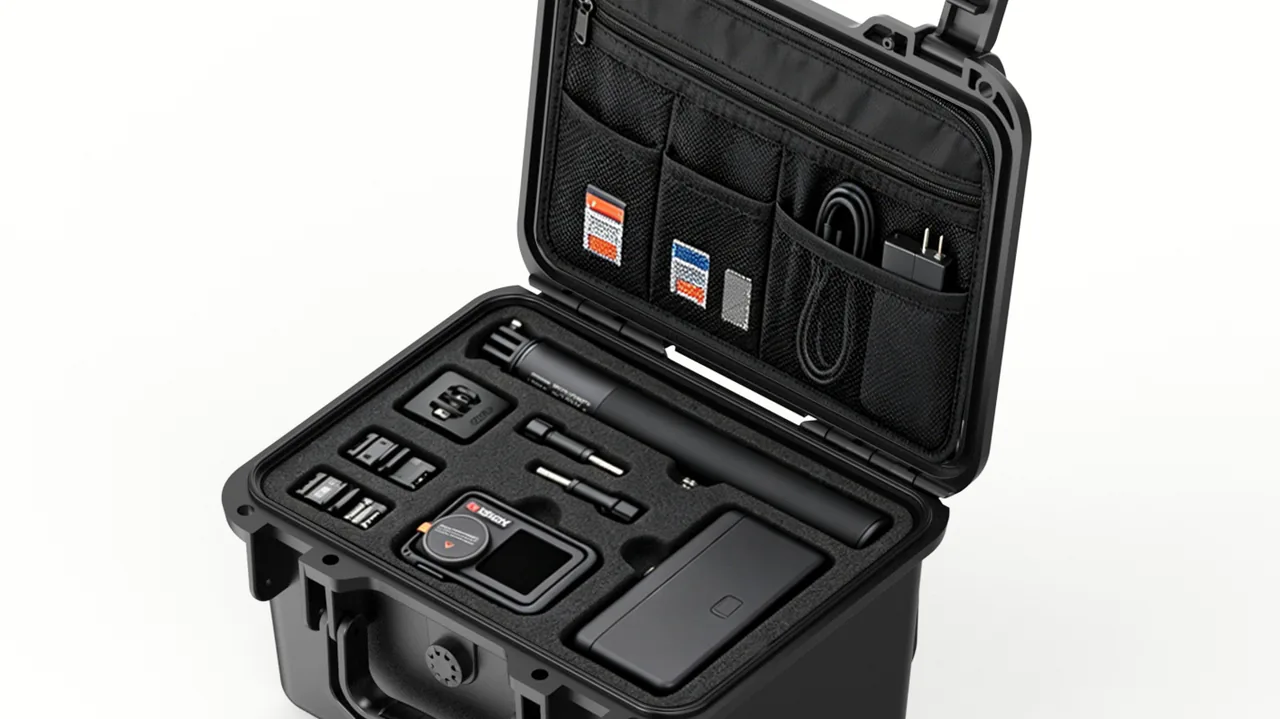
A precision gearbox sample prepared for an overseas exhibition leaves the factory with a noise figure of 62 dB and a backlash of three arc minutes. After air freight, two transfers and four hours stacked in an open-air unloading zone, it measures 71 dB with double the backlash at booth power-up. The shell is undamaged, the paint is unmarked, the paperwork is complete, and yet the unit no longer represents production capability. A second loss appears in the laboratory: a ground coupon at Ra 0.4 micrometre arrives with rust blooms and fingerprint-shaped etching and is rejected as unfit for measurement. In both cases what broke was not the container but the specimen's right to stand in for the batch.
The objective of sample protection is not an undamaged shell but a specimen that still represents its released condition, which means the case has to hold impact, displacement, contact contamination and cavity microclimate inside the window the specimen specification allows. JUNZHIJIA builds sample cases on a four-stage logic: the shell takes stacking and handling loads, the liner takes location and energy absorption, the contact layer governs material compatibility and surface cleanliness, and the sealing and drying system governs humidity and condensation. Drop any one stage and the loss surfaces at the booth or at the bench as an out-of-condition specimen.
Table of Contents
- 1. Display Samples and Test Specimens: Two Different Jobs
- 2. Failure Map: From Surface Damage to Lost Representativeness
- 3. Specimen Classification and Packaging Requirement Matrix
- 4. Shell Material and Moulding Process Selection
- 5. Ingress Protection: Where IP54 to IP67 Apply for Specimens
- 6. Liner Profiling, Layer Stiffness and Fit Tolerance
- 7. Cavities and Removable Dividers: Mixed-Size Loading Rules
- 8. Contact Material Rules: No Lint, No Migration, No Grit
- 9. Cleanliness and Contamination Control for Test Specimens
- 10. Equalisation Valve, Desiccant and Condensation Avoidance
- 11. Transport Validation: ISTA, GB/T 4857 and ASTM D4169
- 12. Stacking, Palletising and the Venue Handling Cycle
- 13. Receiving Inspection, Unpacking and Repacking Sequence
- 14. Frequently Asked Questions FAQ
- 15. Conclusion and Related Reading
1. Display Samples and Test Specimens: Two Different Jobs
Treating these two missions as one is the most common starting point for a failed programme.
A display sample exists to be seen and demonstrated. Visitors touch it, spotlights heat it, and staff power it up repeatedly, so paint, plating, silk screen, transparent covers and edge chamfers must arrive flawless. The case is opened many times per show, so its cycle count far exceeds an ordinary shipping box, and a hairline scratch on a booth reads as poor workmanship.
A test specimen exists to produce defensible data. Its value depends on arriving unchanged: no dimensional drift from sustained compression, no surface contamination or oxidation, no moisture uptake altering mass or hardness, no coating thinning from abrasion. Laboratories state acceptance conditions on the order form, and a specimen that no longer matches its sampling condition invalidates the whole data set.
| Dimension | Display sample | Test specimen |
|---|---|---|
| --- | --- | --- |
| Governing criterion | Flawless appearance, working demo | Reproducible condition, defensible data |
| Opening frequency | High, many times per show | Low, usually a single opening |
| Dominant risk | Scratches, fingerprints, stains, dead demo | Contamination, oxidation, moisture uptake, drift |
| Liner direction | Fast access, presentable layout | Single-set location, no second contact |
| Contact layer | Low lint, non-bleeding, paint safe | Low ions, low extractables, cleanroom grade |
| Documentation | Demo checklist, power-up note | Sampling record, condition photos, hygrometric log |
| Typical cycle | Touring shows, several to dozens per year | One-way submission, occasional retain |
Many organisations run one fleet for both: a unit is displayed and then shipped straight to the laboratory. In that situation the design must follow the laboratory criterion because it is normally the stricter of the two, and the display phase adds a peelable surface film on top. Comparable thinking appears in Footwear Sample Cases and Laboratory Sample Preparation Cases.
2. Failure Map: From Surface Damage to Lost Representativeness
Six mechanisms account for most specimen losses, and none of them announce themselves with a broken shell.
Surface contact damage appears as hairline scratches or haze when paint, anodic layers, chromium plating or acrylic panels rub against liner material under vibration. The threshold is low: a coating around 2H pencil hardness is marked by foam containing hard filler or by coarse fabric. Fingerprint and salt contamination follows bare-hand handling, since a print carries sodium chloride, lactic acid and sebum and initiates local electrochemical attack on bare metal within hours. On stainless coupons this reads as an abnormal surface condition at incoming inspection.
Moisture uptake changes polymers, wood, textiles, paper and composites, with water content driving dimensions, mass, hardness and mechanical results. Residual stress and dimensional drift follow sustained compression on thin walls, slender shafts and sheet parts, particularly where the liner supports at mid-span rather than at the ends and stacking load bends the part. Mating and sealing face bruising kills live demonstrations, because a nicked O-ring groove, sealing cone or spigot leaks on assembly and the usual cause is fasteners and spanners sharing a cavity. Demo function failure covers battery depletion in cold holds, connectors backing out under vibration, and pressure differential darkening liquid crystal panels, and it appears only at energisation, when repair capability is absent.
| Failure mode | Driving variable | Observable sign | Control level |
|---|---|---|---|
| --- | --- | --- | --- |
| Surface scratching | Micro slip plus hard contact | Hairlines, hazing | Low-abrasion contact layer, zero clearance |
| Fingerprint etching | Bare handling plus humid cavity | Print-shaped discolouration | Gloves, desiccant, sealed inner bag |
| Moisture drift | Ambient humidity swing | Mass, size, hardness deviation | Heat-sealed barrier bag, indicator card |
| Permanent set | Static load, wrong supports | Flatness or straightness out | Support at ends, load columns |
| Sealing face bruise | Shared cavity, free travel | Leak on assembly | Separate tool cavity, protective caps |
| Dead demonstration | Cold, vibration, pressure | No response, dark patches | Battery isolation, connector locking, valve |
3. Specimen Classification and Packaging Requirement Matrix
A single consignment may hold anything from an M6 screw to an eighty kilogram machine, so grouping by sensitivity comes before cavity count and liner layering.
| Category | Examples | Sensitive feature | Allowable acceleration | Surface demand | Humidity demand | Packaging key point |
|---|---|---|---|---|---|---|
| --- | --- | --- | --- | --- | --- | --- |
| Machined precision parts | Gauge blocks, coupons, shafts | Size, geometry, roughness | 20-40 g | Very high | Medium, rust | Own groove, VCI bag |
| Coated and plated parts | Painted panels, plating | Gloss, film thickness, adhesion | 30-60 g | Very high, no rubbing | Medium | Soft contact layer, face up |
| Optical and transparent parts | Acrylic covers, lenses | Transmission, haze, scratching | 15-30 g | Very high | Medium | Clean wrap, PE bag, own slot |
| Electronic and powered units | Demo machines, boards, displays | Solder joints, connectors, cells | 30-50 g | High | High | Battery isolation, dissipative liner |
| Polymer and textile pieces | Swatches, webbing, seals | Water content, ageing, marking | 40-80 g | Medium | Very high | Barrier bag, indicator card |
| Powders and granules | Powder, pellets, coating cans | Leakage, caking, cross contact | 20-40 g | Medium | Very high | Sealed bottle, secondary tray |
| Complete machines | Gearboxes, pumps, small plant | Datums, filler, nameplate | 10-25 g | High | Medium | Bottom load beam, top soft stop |
| Tools and consumables | Spanners, cables, manuals | None | Not limited | Low | Low | Separate cavity, never co-loaded |
Any row marked very high for surface demand gets its own groove and is never co-loaded. Any row marked 10 to 25 g is carried on a bottom load beam that transfers into the corner posts rather than on the liner alone.
Sensitivity also changes with the demonstration. A painted panel judged only on gloss needs a soft face; the same panel used for a live cross-cut adhesion demo also depends on film uniformity and edge condition, so the liner must not press on the edge. Confirm the booth action before fixing the liner.
4. Shell Material and Moulding Process Selection
Four conditions compete: bending stiffness against stacking, controllable internal friction behaviour, chemical compatibility with specimens and cleaning agents, and dimensional stability over repeated opening.
| Material system | Process | Density g/cm3 | Wall thickness | Internal friction | Chemical behaviour | Fits |
|---|---|---|---|---|---|---|
| --- | --- | --- | --- | --- | --- | --- |
| Copolymer PP | Injection | 0.90-0.91 | 3-5 mm | Medium, tunable with slip agent | Acids, alkalis, alcohols, salt | General specimens, batch submission |
| ABS | Injection | 1.04-1.06 | 3-5 mm | Low, smooth surface | Attacked by ketones, esters, strong alkali | Presentation cases |
| Rotomoulded LLDPE | Rotomoulding | 0.93-0.94 | 6-10 mm | Medium to high, texturable | Low temperature, acids, alkalis | Machines, large specimens |
| PC/ABS blend | Injection | 1.10-1.15 | 3-4 mm | Low, transparency available | Weak to strong alkali, some solvents | Cases needing viewing windows |
| Aluminium magnesium | Sheet and extrusion | 2.70 | 1.5-2.5 mm | Needs liner isolation | Needs anodising | High value units, shielding |
Three practical points matter. Injected PP creeps one to two percent over thirty days at forty degrees under sustained load, so stacking load must be routed into corner posts through ribs rather than carried by flat panels. Rotomoulded shells give a uniform wall and strong impact behaviour but hold internal tolerances near plus or minus three millimetres, so a precision liner needs an adjustable shim layer or it works loose. Aluminium conducts heat and electricity, making its inner wall the first condensation surface in a temperature swing, and it must be isolated from stainless specimens to avoid a galvanic couple.
Where volume is low and geometry changes often, tooling amortisation argues against a dedicated mould and a standard shell with a custom liner is better; where volume is stable and geometry fixed, a dedicated tool pays back. The decision sequence is set out in Protective Case Type Selection.
5. Ingress Protection: Where IP54 to IP67 Apply for Specimens
IEC 60529 and GB/T 4208 define the code, the first digit covering solid ingress and the second liquid. Selection should follow the wettest node in the route rather than the average condition.
| Rating | Dust | Water | Typical route | Recommended configuration |
|---|---|---|---|---|
| --- | --- | --- | --- | --- |
| IP54 | Category 5 dust | Splash | Local submission, internal transfer | Hard shell, single seal |
| IP65 | Dust tight | Water jet | Domestic road, rain-exposed handling | Hard shell, single seal, drain channel |
| IP66 | Dust tight | Strong jet | Wash-down bays, refrigerated transfer | Hard shell, twin seal, corner guards |
| IP67 | Dust tight | Short immersion | Air, sea, open storage, intermodal | Hard shell, twin seal, equalisation valve |
One boundary must be stated plainly: the code covers water and dust only, not water vapour, chemical mist or condensation. Aircraft holds and sea containers sit above eighty percent relative humidity for days, and day-night cycling turns the wall into a condensing surface alternately, which a better sealed shell makes worse because humidity trapped at closing has nowhere to go. That is why an IP67 specimen case on a long route must carry desiccant and an indicator card, a point developed further in Differences Between IP65, IP66 and IP67.
Verification is best done by vacuum retention: draw down to minus twenty kilopascals, hold five minutes, and accept a drop of no more than one kilopascal. This is more sensitive than immersion and never introduces water into the seal groove. Where the route includes heavily dusty loading yards, the self-clearing seal groove geometry in Dustproof Cases for Dusty Environments is worth copying.
6. Liner Profiling, Layer Stiffness and Fit Tolerance
The liner decides whether the programme succeeds. Three attributes govern: profiling accuracy, stiffness layering and fit clearance.
Profiling should come from three-dimensional scanning or a measured model rather than a few calliper dimensions. Interference on a shaped specimen usually hides at an unremarkable boss, handle or cable; miss one and the liner lifts the part on that feature while every other face hangs unsupported.
Stiffness layering exists because a single layer cannot both isolate and locate. The standard build uses an outer layer of twenty-five to thirty kilogram per cubic metre EPE for energy absorption and an inner layer of fifty to sixty kilogram per cubic metre EVA or IXPE for location and stiffness. The layers are not bonded, so slight relative sliding adds frictional damping, and specimens with extreme surface demands receive a further three to five millimetre soft contact facing.
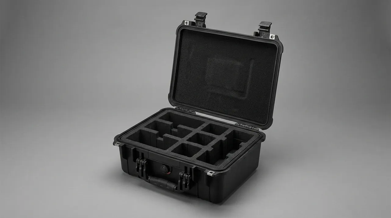
Fit clearance is the attribute most often compromised. Single-side clearance between cavity and specimen must stay between half a millimetre and one millimetre. At three millimetres the specimen free-travels before striking the liner, which is equivalent to raising the drop height by three millimetres and raises measured peak acceleration by more than half.
| Material | Density kg/m3 | Stress at 25 percent | Recovery | Abrasion behaviour | Role in a sample case |
|---|---|---|---|---|---|
| --- | --- | --- | --- | --- | --- |
| EPE expanded polyethylene | 25-35 | 0.10-0.18 MPa | Above 90 percent | Granular surface, use care on paint | Outer energy layer |
| EVA | 40-80 | 0.25-0.50 MPa | Above 95 percent | CNC routable, tight tolerance | Inner locating layer, dividers |
| IXPE cross-linked PE | 30-60 | 0.15-0.35 MPa | Above 90 percent | Fine surface, thin gauges | Contact facing |
| PU foam | 25-45 | 0.08-0.20 MPa | Above 90 percent | Soft, conforms, sheds crumb | Wrapping irregular shapes |
| Flocked composite foam | 40-60 | 0.20-0.40 MPa | Above 90 percent | Low abrasion, paint safe | Preferred contact for display units |
Thickness follows a simplified energy model: delta equals two times H divided by a_max, where delta is the usable compression travel in metres, H the drop height in metres, and a_max the allowable acceleration expressed in multiples of g. With H at 0.6 metres and a_max at 25 g, delta is 0.048 metres; a safety factor of 1.3 to 1.5 gives an actual thickness of roughly 62 to 72 millimetres. Processing routes and tooling trade-offs are covered in EVA Foam Insert Custom Process and EPE Versus EVA Foam Behaviour.
7. Cavities and Removable Dividers: Mixed-Size Loading Rules
The usual consignment carries a dozen sizes, and the booth demands that any one of them be found in minutes, so cavity design has to solve location and access together.
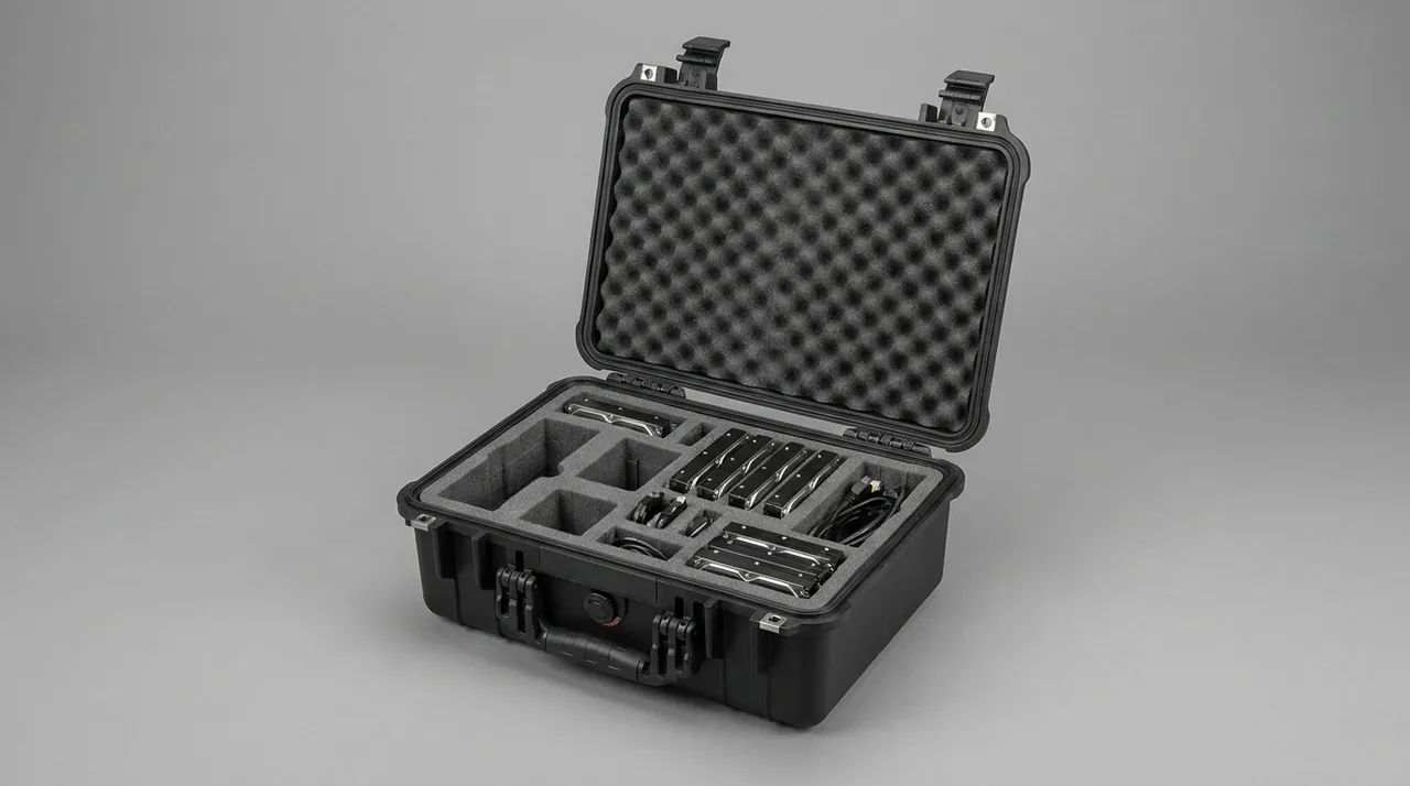
Four rules apply. Grade cavities by sensitivity rather than size: optics, coatings and gauge blocks take grade one with individual grooves and soft facing; ordinary structural parts take grade two; spanners, cables and fasteners take a grade three tool cavity. Misgrading is the main cause of mixed-load damage. Give every specimen its own groove and never stack them, because stacking multiplies local pressure on the lower piece and guarantees sliding contact during access. Fit a top retaining bar on any removable divider, since many incidents happen not at the drop but when the case tilts and the divider falls; bar to lid clearance should stay under two millimetres. Keep the access path single-direction, so a specimen lifts vertically without first removing its neighbour, because angled extraction under time pressure is where bruises come from.
| Cavity grade | Contents | Liner form | Contact requirement | Marking |
|---|---|---|---|---|
| --- | --- | --- | --- | --- |
| Grade one | Optics, coatings, gauge blocks | Individual groove, soft facing | Flocked or IXPE facing | Specimen ID plus up arrow |
| Grade two | Structural parts, swatches, modules | Divided grooves | IXPE or EVA direct | Specimen ID |
| Grade three | Tools, cables, fasteners | Open bins | No special requirement | Contents list on cavity lid |
| Document pocket | Reports, lists, certificates | Mesh pocket or flat sleeve | Moisture barrier bag | Not required |
Where specimen geometry changes with each show theme, a removable divider system beats a fully sculpted liner on reusability and rework cost, as analysed in Removable Divider System Design.
8. Contact Material Rules: No Lint, No Migration, No Grit
Surface demand drives contact layer selection, and this is where a sample case parts company with ordinary industrial transit packaging. The facing has to satisfy three negative conditions. No lint: long pile fabric and flocked foam shed fibres that settle on the specimen and show as fluff under booth lighting, so use a fine closed-cell material or a short pile composite with no loose fibre. No migration: plasticisers, cure residues and unreacted monomer diffuse slowly out of soft materials and deposit a haze on high gloss or optical surfaces that is very difficult to remove, so ask the supplier for extractables data and insert an inert polyethylene film for high risk specimens, confirming the film itself is plasticiser free. No grit: hard particles in foam stock from regrind, filler agglomerates or cutting debris act as an abrasive under vibration, so blow out or wipe every routed cavity after cutting and inspect again before assembly.
| Contact material | Advantage | Risk | Fits |
|---|---|---|---|
| --- | --- | --- | --- |
| Flocked composite foam | Low abrasion, presentable | Poor grades shed pile | Painted and plated parts |
| IXPE thin facing | Fine surface, no shedding | Limited thickness, relies on layer below | Optical and acrylic parts |
| Inert PE barrier film | Zero migration, zero shedding | No cushioning of its own | High gloss and mirror finishes |
| VCI paper or bag | Adds corrosion inhibition | Paper sheds, avoid on optical faces | Machined metal parts |
| Bare EPE direct contact | Low cost | Granular, marks paint | Forbidden in grade one |
Handling discipline matters equally: wear powder free nitrile or cotton gloves, never touch metal or optical faces bare, cover benches with a soft mat, and clean only with the specified lint free cloth and solvent. A single bare-handed pick-up at the booth can undo everything the liner achieved.
9. Cleanliness and Contamination Control for Test Specimens
Test specimens tolerate far less contamination than display units, because contamination decides whether a report is accepted at all.
At sampling, photograph the surface immediately, log time, ambient temperature and humidity, sampling position and batch number, and place the piece in its primary pack, usually a clean polyethylene bag or a vapour corrosion inhibitor bag. Those photographs are the only way to later separate transport damage from sampling damage. At packing, add a humidity indicator card, typically graduated at five, ten and fifteen percent or at ten, twenty and thirty percent, plus the calculated desiccant charge, then heat seal or zip close. For metal parts, vapour corrosion inhibitor outperforms desiccant, because the inhibitor forms a monomolecular film on the metal and works independently of humidity; for moisture sensitive polymers and textiles, use a heat sealed foil laminate barrier bag that stops vapour exchange outright. At case loading, the cavity must be profiled to the packed envelope rather than to the bare part, a step routinely missed, since liners cut to the bare component let the sealed bag bulge and lift the specimen out of its seat.
| Specimen type | Primary pack | Drying or corrosion scheme | Hygrometric record |
|---|---|---|---|
| --- | --- | --- | --- |
| Machined metal | VCI bag | VCI plus card at or below 20 percent | One reading on arrival |
| Coated and plated | Clean PE bag with soft separator | Desiccant plus card at or below 20 percent | One reading on arrival |
| Polymer and textile | Heat sealed foil barrier bag | Molecular sieve 4A, card at or below 10 percent | Continuous logger |
| Powder and granular | Sealed bottle in secondary tray | Desiccant, sealed closure | One reading on arrival |
| Biological and pharmaceutical | As specified by the client | Cold chain or controlled temperature | Continuous logger, exported |
Routes touching biological, pharmaceutical or food sectors impose tighter packaging and documentation regimes; the layered approach in Medical Sample Transport Cases transfers well, and for general industrial specimens the isolation logic in Laboratory Sample Preparation Cases is the closer reference.
10. Equalisation Valve, Desiccant and Condensation Avoidance
Pressure and humidity inside a sealed cavity cause more trouble than almost anything else and are the hardest to remedy after the fact. Under the ideal gas approximation at constant volume, the differential tracks the absolute temperature difference: falling from twenty degrees, 293 kelvin, to minus twenty degrees, 253 kelvin, produces about 13.7 percent of initial absolute pressure, roughly fourteen kilopascals, while an aircraft hold pressurised to an equivalent of seventy-five kilopascals reaches twenty-five to thirty kilopascals. That is enough to press the gasket into its groove, bow the wall inward onto the liner, and load thin walled specimens.
The equalisation valve uses an expanded PTFE membrane with pores of 0.1 to 1 micrometre, far below the smallest liquid droplet at about twenty micrometres, while water vapour at roughly 0.0004 micrometres passes freely; typical flow rates run from fifty to three hundred millilitres per minute per square centimetre per bar. Mount it on a side wall above any water collection line, never in a top recess or on the floor.
Desiccant charge can be estimated from silica gel equilibrium uptake of about twenty percent of its own mass at twenty-five degrees and forty percent relative humidity:
| Internal volume m3 | Road, up to 7 days | Air plus venue turnaround, 10 days | Sea, 30 days | Tropical route, 45 days, sieve 4A |
|---|---|---|---|---|
| --- | --- | --- | --- | --- |
| 0.02 | 15 g | 20 g | 25 g | 20 g |
| 0.05 | 35 g | 45 g | 60 g | 45 g |
| 0.10 | 70 g | 90 g | 120 g | 90 g |
| 0.20 | 130 g | 170 g | 230 g | 170 g |
Molecular sieve 4A outperforms silica gel at low humidity and can be dosed at sixty to seventy percent of the silica figure, which suits moisture sensitive specimens.
Three measures limit condensation: leave two to three millimetre vent channels in the liner so vapour reaches the desiccant evenly instead of pooling in a dead pocket; avoid placing a large metal face directly against a large plastic face, because the conductivity difference makes the metal the preferred condensing surface during a rapid change; and let the case equilibrate with ambient for two to four hours before opening so warm specimens do not meet cold air. Desiccant only removes vapour already inside and cannot substitute for sealing, and the valve makes vapour travel both ways, so the charge belongs inside the primary pack rather than loose in the cavity, giving a breathing outer shell around a closed inner envelope.
11. Transport Validation: ISTA, GB/T 4857 and ASTM D4169
A design cannot validate itself; it needs test data, and the programme normally runs at two levels, case and specimen.
| Standard | Level | Principal items | Specimen acceptance addition |
|---|---|---|---|
| --- | --- | --- | --- |
| ISTA 1A / 2A | Whole case, up to 68 kg | Drop, random vibration, stacking | No dimensional or geometric change |
| ISTA 3A | Whole case, parcel | Drop, random vibration, compression | No new surface marking |
| GB/T 4857.5 / .7 / .3 | Whole case, domestic | Drop, sine vibration, stacking | Coating unworn, sealing faces unbruised |
| ASTM D4169 DC13 | Whole case, air plus road | Low pressure, vibration, drop | Pressure within limit, no moisture uptake |
| IEC 60068-2-27 Eb | Specimen | Half sine shock, 15 g, 11 ms | No structural displacement |
| IEC 60068-2-64 Fh | Specimen | Random vibration, 10 to 500 Hz | Parameter drift within tolerance |
The two conclusions must not be confused. A passing case test says the combination protected the specimen under that spectrum; a passing specimen test says the specimen tolerates that level of direct excitation but says nothing about stacking, low pressure or repeated transfer loads. A complete report carries both, and re-measures the specimen after every run.
Drop attitude and count need stating too. A frequent omission is testing faces only, while corner impacts dominate real incidents because handlers set cases down on a corner. Cover at least one corner, three edges and six faces. It should also be recorded that the ISTA and GB/T 4857 families evaluate packaged performance under defined spectra that cannot reproduce a real route exactly; results rank options and screen risk rather than promising zero damage on any particular consignment.
12. Stacking, Palletising and the Venue Handling Cycle
What separates a sample case from other transit packaging is the venue: repeated handling and temporary storage between flights.
Bottom layer load follows P equals m times n minus one times k, where P is the load on the bottom case in kilograms, m the gross mass of one case, n the number of tiers and k a dynamic factor usually taken between 1.5 and 2.0. With a gross mass of 22 kilograms, five tiers and k at 1.8, the bottom case carries 22 x 4 x 1.8, about 158 kilograms. Over a footprint of 0.10 square metres that is roughly 15.5 kilopascals, close to the stress of medium density EPE at twenty-five percent compression, so if that load reaches the liner instead of the posts the specimen stays compressed for the whole journey.
| Stage | Dominant load | Typical risk | Control |
|---|---|---|---|
| --- | --- | --- | --- |
| Vehicle loading | Static stack plus braking inertia | Prolonged compression of bottom units | Tier limit, palletisation |
| In transit | Random vibration, thermal cycling | Micro slip, condensation | Zero clearance, desiccant |
| Open yard storage | Solar gain, rain | High cavity humidity, hot paint | IP65 or better, shade and cover |
| Manual venue handling | Tilt, knock, drop | Corner impact, divider fall | Wheels and handle, divider bar |
| Booth unpacking | High cycle opening | Latch fatigue, wrong pick | ID labels, unpacking list |
| Repacking after show | Time pressure, poor light | Missing, swapped, reversed parts | Poka-yoke cavity, pack photos |
Pallet height should stay under 1.5 metres per pallet, wrapped with corner protection. Marking follows GB/T 191 and GB/T 13384, covering this way up, keep dry, centre of gravity and stacking tier limit. Maximum tier count and gross mass must be printed on the case, otherwise the site will over-stack to save floor. Long term creep also counts: polypropylene creeps one to two percent in thirty days at forty degrees, and a sea container can reach sixty degrees, so practical limits are set at eighty percent of the design tier count.
13. Receiving Inspection, Unpacking and Repacking Sequence
Acceptance criteria belong on the packing list, not in an operator's memory. Split acceptance into appearance, condition and documentation.
| Item | Method | Criterion | Nonconformance action |
|---|---|---|---|
| --- | --- | --- | --- |
| Shell | Visual, open and close | No penetration, no crack, smooth action | Photograph, move to hold area |
| Water or moisture marks | Visual, absorbent paper | No seepage trace, no frosting | Isolate and re-inspect specimens |
| Humidity indicator | Read card | At or below 20 percent, 10 percent for polymers | Re-dry, then re-inspect |
| Liner movement | Feeler gauge, imprint check | No travel mark beyond 1 mm | Recalculate fit tolerance |
| Specimen surface | Raking light, magnifier | No new scratch, etch or lint | Compare with sampling photo |
| Size and geometry | Re-measure key features | Matches release record | Send for metrology review |
| Powered function | Energise | Matches release record | Check cells and connectors |
| Documentation | List check | Packing list, condition photos, hygrometric log complete | Complete the file |
Unpacking and repacking both need a fixed sequence, because the wrong order itself causes damage. Confirm shell condition and read the indicator card. Remove cavity by cavity from the top down by ID, never reaching across. Compare each piece with its sampling photograph immediately. Repack following the poka-yoke orientation and photograph the finished case. The two photo sets create a traceable record that settles whether damage happened in transit or during packing.
For touring fleets, keep a case re-inspection log. After each show cycle check latch feel, hinge clearance, gasket compression recovery, wheel wear and cavity collapse, and repair or retire against the stated criteria.
14. Frequently Asked Questions FAQ
Q: How does a sample case differ from an ordinary industrial parts transit case in its design?
A: The difference is the acceptance criterion. A parts case is judged on nothing broken, nothing lost and nothing mis-picked, so it targets structural integrity and count accuracy. A sample case is judged on whether the specimen still represents its released condition, so it targets surface, dimensions, water content and demonstration function. That shift produces three design forks. The contact facing has to be lint free, non-migrating and grit free, where an ordinary case uses plain expanded polyethylene. Fit clearance has to sit between half a millimetre and one millimetre to remove micro slip, where an ordinary case tolerates a looser seat. Documentation has to travel with the case, including sampling condition photographs and arrival re-measurement records, because without them the stage at which damage occurred cannot be established. Finally, a sample case opens far more often, so latch, hinge and liner fatigue life is calculated in cycles rather than in shipments. A touring fleet also benefits from a per-case log that records latch feel, hinge clearance and cavity condition after every show, so wear is caught before it reaches the specimen rather than during a build.
Q: Can one case design serve both display samples and laboratory specimens?
A: Yes for the shell and most of the liner structure, provided the design follows the laboratory criterion and the display phase adds a peelable surface film. The laboratory criterion is normally stricter, because a specimen must reproduce its condition and any moisture uptake, oxidation or micro abrasion can invalidate the data set, whereas a display unit is judged on visible appearance. The practical cost of dual service sits in the contact facing and the packing method. Laboratory work needs a primary pack, whether a clean polyethylene bag, a vapour corrosion inhibitor bag or a foil barrier bag, together with a humidity indicator card. Display work prefers a flocked facing and open grooves that allow fast access. Where one fleet does both, profile the liner to the laboratory requirement and add a quick-fit surface film and display cradle for the booth, which keeps one inventory without compromising the data. Where the two missions are separated in time, the simpler route is a dedicated barrier bag that stays sealed throughout the show and is opened only at the laboratory bench, so the specimen never meets booth air at all.
Q: Why insist on near zero clearance when a looser cavity makes access easier?
A: Looseness buys two problems, micro slip and free travel. With three millimetres of clearance the specimen moves slightly inside its cavity throughout the journey and rubs the facing continuously; over tens of hours of vibration that produces hazing on paint, plating and optical faces, which is very visible under booth lighting. Free travel is worse at impact: the specimen crosses the gap before striking the liner, which is equivalent to raising the drop height by three millimetres and can raise measured peak acceleration by more than half, enough to exceed the fifteen to thirty g allowance on optical parts. Access should be solved by cavity geometry rather than by slack, meaning a vertical lift path that needs no neighbour removed, plus a finger recess or lifting tab at the cavity edge so the part comes out straight without prising. Where a specimen must be tilted to clear a neighbouring divider, add a local relief cut rather than widening the whole cavity, so the tight fit survives where it actually matters.
Q: Should a metal test specimen use a vapour corrosion inhibitor bag or desiccant with an indicator card?
A: The mechanisms differ, so the choice follows the specimen. Desiccant physically adsorbs water vapour and removes the electrolyte that corrosion needs, but it only handles moisture already inside the pack and its capacity is finite, so on long or humid routes it saturates part way through. Vapour corrosion inhibitor releases molecules that form a monomolecular protective film on the metal and blocks the reaction directly, working even at elevated humidity and independently of moisture control. Machined metal parts therefore favour an inhibitor bag with an indicator card. Polymers, textiles and paper are the opposite case, because their problem is water content rather than corrosion, so they need a heat sealed foil barrier bag with molecular sieve 4A. In both cases the charge belongs inside a sealed primary pack rather than loose in the cavity, otherwise vapour arriving through the equalisation valve will exhaust it before it is needed. Whatever scheme is chosen, record the indicator reading at packing and again at arrival, because the pair of readings is what proves whether the barrier held and is often the only evidence a laboratory will accept.
Q: How should latches and hinges be selected and checked for a case opened constantly at shows?
A: Check against opening cycles rather than shipments. One touring show involves unpacking at build, daily removal, daily return and repacking at breakdown, so ten shows a year reach several hundred cycles and two seasons approach a thousand. For selection, use a metal latch body on a stainless pivot, because plastic catches develop stress whitening and then fracture at the claw root under repeated opening. Choose a full length through hinge over separate leaves, since a through axle distributes load evenly and avoids one side sinking, which would misalign the lid and relieve gasket pressure locally. Specify 316 stainless throughout and rank options with a neutral salt spray run of forty-eight to ninety-six hours to GB/T 10125. For maintenance, keep a per-case log and inspect latch feel, hinge clearance, gasket recovery and wheel wear after every cycle, repairing or retiring against stated limits. Cycle counting also tells a fleet manager when to budget hardware replacement, since a latch that has completed most of its rated cycles can be changed at the depot rather than failing at a build with no spare on site.
Q: Why is a two stiffness liner recommended for sea freight and long routes?
A: Because a long route applies two conflicting load families. Low frequency excitation, one to twenty hertz from wave action at sea or three to eight hertz from suspension bounce on road, favours a soft liner that isolates vibration and prevents the prolonged rubbing and permanent set it causes. Handling and stacking impacts favour a firm liner that limits displacement so the specimen cannot strike a divider or the wall. A single stiffness can only compromise and will sacrifice one of the two. The layered build separates the functions instead: an outer layer of twenty-five to thirty kilogram per cubic metre expanded polyethylene absorbs impact energy and isolates vibration, while an inner layer of fifty to sixty kilogram per cubic metre EVA or cross-linked polyethylene provides location and stiffness. The layers are deliberately unbonded, so slight relative sliding contributes frictional damping, keeping the first natural frequency clear of the dominant band while holding displacement under one millimetre. The same reasoning explains why a soft liner alone is not the answer on long routes: it isolates well but lets the specimen travel far enough to contact a divider or the wall under a handling shock, and contact damage is permanent.
Q: If the case passes an ISTA whole case test, is specimen level testing still needed?
A: Yes, because the two answer different questions and neither substitutes for the other. The whole case test examines the combination of shell, liner and specimen and concludes that this combination protects the specimen under that particular spectrum; it says nothing about how much direct excitation the specimen itself tolerates. Specimen level work such as IEC 60068-2-27 half sine shock or IEC 60068-2-64 random vibration examines the specimen alone and concludes that it survives that level of direct input, but says nothing about stacking, reduced aircraft pressure or repeated transfer loads. A complete programme needs both, and must re-measure key dimensions, geometry, surface condition and function parameters after every run so that the finding becomes condition unchanged rather than structure undamaged. The drop plan should also cover edges and corners, since corner impacts dominate real incidents and a faces-only plan misses the most common failure attitude. Specimen re-measurement after each run is what converts a passing case test into evidence of condition unchanged, and without it a case can pass while the specimen quietly leaves tolerance.
Q: When should a touring sample case be retired from service?
A: Retire on measured criteria rather than on age. For the shell, retire when a through crack appears, when corner damage reduces stacking capacity, when a deformed seal groove lets vacuum retention decay beyond one kilopascal, or when lid misalignment relieves gasket pressure locally. For hardware, replace rather than scrap when a latch claw shows a visible crack or stress whitening, when hinge clearance exceeds 1.5 millimetres and cannot be adjusted, or when wheels show uneven wear or a seized bearing. For the liner, rebuild when a cavity has taken permanent set and clearance exceeds one millimetre, when the facing sheds lint or deposits extractables on the specimen, or when a divider retaining bar no longer holds. Replace gaskets when compression recovery falls below eighty-five percent of original thickness. A per-show inspection log with photographs turns retirement from a judgement call into a traceable decision and keeps a tired case off the stand.
15. Conclusion and Related Reading
Specimen transport is about carrying a released condition intact to the stand or the bench. JUNZHIJIA supports that with liner profiling, multi-cavity layout, contact layer selection, OEM and ODM programmes, and full shipping documentation.
Related Reading