

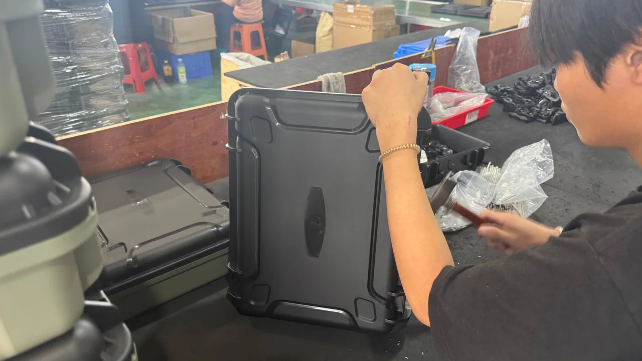
A municipal wastewater plant upgrade or an industrial effluent project rarely arrives as one machine. It arrives as hundreds of parts shipped in batches: MBR membrane modules and membrane sheets, disc and tubular aerators, Roots and centrifugal blowers, submersible mixers, sewage pumps, filter plates for dewatering presses, dosing pumps and online instruments. The moment these parts leave the assembly line they are at their best and at their most fragile. They then face hundreds or thousands of kilometres by road, rail or sea, several transfers, hoisting operations and open-air staging before they are finally installed in tanks, pipework and plant rooms.
The sewage environment itself adds a second layer of difficulty. These parts are designed to meet water, humidity, chlorides, hydrogen sulphide, oil and biological fouling, so their tolerance for damp and corrosion is far lower than that of ordinary industrial equipment. JUNZHIJIA holds that protection for sewage treatment equipment must be designed at component level rather than machine level: membrane fibres and sheets must resist creasing, drying, freezing and compression; aeration elastomers must resist permanent set and oil; rotating machinery must resist moisture, vibration and cable-root failure; and stainless parts must resist chloride pitting. Those four directions differ from each other, and any plan that expects one waterproof plastic case to cover them all will leave a permanent defect on at least one component.
Table of Contents
- Mapping Failure Modes in Sewage Equipment Storage and Transit
- Membrane Modules: Fibres, Permeate Headers and Seal Interfaces
- MBR Frames, Cassettes and Aeration Manifolds: Mutual Damage Paths
- Aerators and Diffusers: Elastomer Membranes and Porous Parts
- Blowers, Submersible Mixers and Sewage Pumps: Location and Vibration
- Corrosion, Scaling and Biofouling: Containment Before Dispatch
- Moisture, Condensation and Odour: Controlling the Case Microclimate
- Sealing and Pressure Equalization: IP65, IP67, Altitude and Temperature
- Cushion Liners and Compartments: EPE, EVA, IXPE and PE
- Vibration, Shock and Stacking Verification
- Temperature, Humidity, Salt Spray and Test Basis
- Arrival Acceptance Checklist and Re-Inspection
- Model Selection Chart and Bespoke Flow
- Frequently Asked Questions FAQ
- Conclusion and Related Reading
Mapping Failure Modes in Sewage Equipment Storage and Transit
Sewage plant components fall into four families: wet separation parts such as membrane modules; elastomer and porous parts such as aerators and diffusers; rotating machinery such as blowers, mixers and pumps; and metal or brittle structural parts such as valves, flanges, brackets and instruments. When these families share one case, their sensitivities differ and they can damage each other.
Membrane modules fear creasing and dehydration. A hollow fibre may be only one or two millimetres across with a wall well under half a millimetre, so a hard edge pressed against it during packing becomes the starting point of a broken fibre in service; if a membrane dries out in transit, its pore structure shrinks irreversibly and flux never fully recovers. Aerators fear compression set. EPDM and silicone membranes held under load do not spring back completely, so the open area drops, air distribution becomes uneven, oxygen transfer efficiency falls and blower energy rises. Rotating machinery fears moisture and vibration. Blowers and submersible pumps contain bearings, gears, mechanical seals and electrical insulation; condensation inside the case lowers insulation resistance, while resonance during transport accelerates bearing and seal failure. Metal parts fear chlorides and galvanic corrosion. Grade 316L pits and cracks under stress in warm chloride-bearing conditions, and when it touches a carbon steel bracket directly it forms a galvanic cell.
| Failure mode | Main trigger | On-site consequence | Packaging countermeasure |
|---|---|---|---|
| --- | --- | --- | --- |
| Broken fibres, scratched membrane | Hard-edge crushing, vibration rub, drop | Higher turbidity, whole module replaced | Form-cut cradles, soft clamping, no nesting |
| Membrane dried and shrunk | Dry shipping, high case temperature | Irreversible flux loss | Sealed wet packing, preservative, shade |
| Aerator membrane set | Long stacking, point loading | Uneven aeration, higher energy use | Individual cradles, load limits, no stacking |
| Porous diffuser blocked | Dust, oil, debris in pores | Higher pressure loss, poor distribution | Face protection, inner wrap, clean packing |
| Insulation resistance drop | Condensation, residual moisture | Trip on energising, winding breakdown | Desiccant, humidity card, seal plus valve |
| Stainless pitting and cracking | Chlorides, moisture, galvanic contact | Lower strength, through-wall leaks | VCI release, isolating pads, dry packing |
| Cable root broken | Cable used as a lifting point | Water ingress, short circuit | Cable clamp, dedicated coiled pocket |
| Precision part loses calibration | Shock and resonance | Instrument drift, coupling offset | Cushion liner, damping, tested layout |
The lesson from that table is simple: packing sewage equipment is not about putting parts into a box, it is about isolating each sensitive point one by one. Where isolation is missing, the problem does not appear on arrival but surfaces all at once on the day the plant is commissioned.
Membrane Modules: Fibres, Permeate Headers and Seal Interfaces
Membrane modules are the most expensive and least reworkable items in any shipment. Three forms dominate: hollow fibre (HF), flat sheet (FS) and ceramic. Hollow fibre membranes, common in MBR and outside-in ultrafiltration, bundle fibres into an epoxy or polyurethane potted head, with permeate collected through a header. Flat sheet membranes pair a support plate with a sheet on each face and connect through a frame and permeate port. Ceramic membranes use an alumina, zirconia or silicon carbide separation layer, strong in compression yet distinctly brittle.
The first risk is creasing and crushing. Membrane fibres and flat sheets are designed for uniformly distributed water pressure, not for point contact. If a module is left unsupported, stacked on top of another, or lashed with a thin cord across the membrane face, fibres take a permanent fold and flat sheets may delaminate from the support plate. The correct attitude for a hollow fibre module is upright, carried on a form-cut cradle under the potted heads, so that the heads carry the weight and the fibres carry nothing.
The second risk is dehydration and freeze damage. Many membranes ship wet, immersed in water containing a preservative that suppresses microbial growth and keeps pores wetted. If the wet wrap is punctured or the case gets hot, water evaporates and pores collapse. Conversely, if a water-filled module freezes on a winter route, expanding ice cracks fibres and potted heads, and the damage is irreversible once thawed. Wet modules therefore need a packing design that answers both retention and freeze protection.
The third risk is contamination of seal interfaces. Permeate headers, permeate ports, O-ring grooves and end-cap flanges are low-roughness sealing faces; a single grain of sand, a smear of oil or adhesive residue will cause a leak after assembly. Each of these faces should be taped or capped individually and kept strictly separate from oily or dusty metal parts.
| Membrane type | Typical materials | Transport sensitivity | Packaging focus |
|---|---|---|---|
| --- | --- | --- | --- |
| Hollow fibre | PVDF, PES, PS | Creasing, dehydration, freezing | Upright cradle, wet wrap, freeze liner |
| Flat sheet | PVDF sheet plus ABS plate | Delamination, plate warping | Flat cradle, face protection, load cap |
| Ceramic | Al2O3, ZrO2, SiC | Brittle fracture, chipped edges | One part per pocket, radiused pads |
| Spiral wound | Composite polyamide | Central tube distortion, seal ageing | End-cap protection, dry and dark |
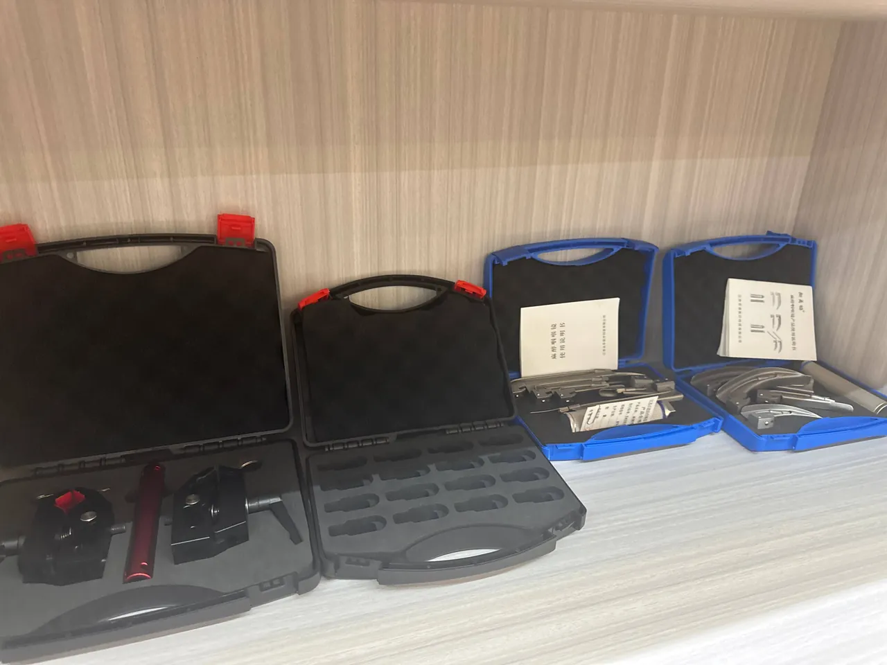
For wet modules the industry norm is a two-layer build: a preservative-filled sealed bag inside an outer case, with a small free liquid surface so no part of the membrane dries locally. In winter, freeze protection comes from insulated liners, controlled-release heat packs or a preservative blend with a lowered freezing point. Whether to ship wet or dry is a decision for the membrane supplier to state in the technical agreement; the packaging design follows that decision and should never override it.
MBR Frames, Cassettes and Aeration Manifolds: Mutual Damage Paths
Modules rarely travel alone. They usually ship as a frame or cassette, meaning several membrane elements, a permeate manifold, aeration laterals and a lifting frame are assembled into one unit. The risk structure then changes from part-against-wall to relative movement between frame, membranes and pipework.
A frame is normally welded from grade 304 or 316L stainless square tube, stiff and with concentrated mass. Under transport vibration the frame moves as a rigid body while membranes and aeration laterals retain some freedom. The resulting micro-motion rubs membrane faces and wears through lateral coatings within a short distance. Inside a cassette, positive location matters more than cushioning: a hard stop combined with a soft pad between frame and case wall, and between membrane stacks and frame, limits relative travel to a few millimetres while ensuring no rigid point presses directly on a membrane face.
The lifting frame is a natural tie-down point, but its loads travel through the frame into the membranes. If packing relies on straps pulling down from the lifting points, strap tension bends the frame and the bending reaches the membrane edges. The safer arrangement is to let the frame base rest on load beams so vertical load transfers directly to the case floor, and use straps only for horizontal location.
Cassette permeate and air flanges usually arrive blanked or capped, but the bolt holes are a weak point: a nut that works loose and wanders inside the case will scratch a membrane face. Accessories such as bolts, gaskets, clamps and special tools must go into dedicated compartments and be listed on the packing sheet, so the first action after opening is a count.
Aerators and Diffusers: Elastomer Membranes and Porous Parts
Aeration is the largest energy consumer in a treatment plant, and its parts take many forms: elastomer discs for disc diffusers, elastic tubes for tubular diffusers, alumina or ceramic fine-bubble diffusers, and metal nozzles for jet and vortex aerators. They share three packaging enemies: load, oil and dust.
The dominant failure mechanism of a rubber membrane (EPDM, silicone, polyurethane) is compression set. Under sustained load the material relaxes and does not fully recover, so the opening geometry changes and air distribution becomes uneven. Aeration membranes should therefore never be stacked under load for long periods, and never be weighed down. Disc diffusers belong one per pocket, lying flat; tubular diffusers should be supported at several points along their length so nothing sags and presses on the membrane.
Ceramic and alumina fine-bubble diffusers are brittle. Their compressive strength is high but their impact resistance is poor, so a knock on an edge can chip it, disturbing pore distribution and creating a leakage path. They also fear oil: once lubricating or vegetable oil enters the pores it forms a hydrophobic film on the pore wall that resists wetting in service, and that zone stops working. These parts need a clean inner wrap, gloved handling and separation from oily machinery.
| Aerator type | Core materials | Transport sensitivity | Packaging points |
|---|---|---|---|
| --- | --- | --- | --- |
| Disc diffuser | EPDM or silicone disc on ABS body | Compression set, membrane punctured | One per pocket, flat, load capped |
| Tubular diffuser | Elastic membrane on UPVC body | Tube bending, membrane scratched | Multi-point support, end protection |
| Ceramic diffuser | Alumina, corundum | Chipped edges, pores clogged by oil | Separate pockets, clean wrap, no oil |
| Jet or vortex aerator | Stainless or engineering plastic | Nozzle bore scratched, flange distortion | Nozzle plugs, taped flange faces |
| Aeration hose | Reinforced PVC or PU | Flattened, crushed | Coiled pocket, large bend radius |
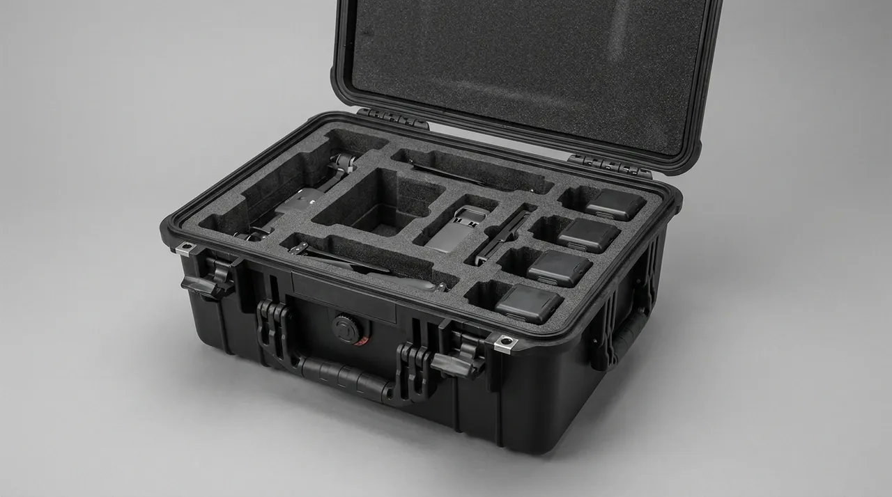
One easily missed detail is the installation kit. Aeration systems are commissioned on site with matching membranes, clamps, gaskets and a special spanner, and if these accessories are loose at the bottom of a large case, the search process itself contaminates the porous parts. Pack the installation accessories as a separate kit, in the same case but in their own compartment, with the contents cross-checked against the packing list.
Blowers, Submersible Mixers and Sewage Pumps: Location and Vibration
Rotating machinery follows completely different logic from the families above. Its enemies are not surface scratches but bearings, gears, mechanical seals and motor insulation. Roots, centrifugal and screw blowers, submersible mixers and sewage pumps all belong here, and protection centres on two ideas: constraining motion and controlling humidity.
Vibration is the primary enemy. Vehicle and vessel vibration is concentrated between a few hertz and a few tens of hertz, and a rotor-bearing system has natural frequencies of its own. When the two approach each other, the part inside the case experiences far greater vibration than the vehicle itself, producing bearing race pitting, gear micro-motion wear and fatigue of coupling inserts. The answer is not simply "add soft foam" but rigid location first, damping second: lock the feet, flanges and base bolt holes to a pallet with locating blocks so that part and pallet move as one body, then place damping pads between pallet and case floor. Soft pads alone let the part keep moving and can be worse than a hard fix.
Submersible equipment carries an extra risk at the cable root. Where the cable leaves the housing there is a sealing and clamping structure, and if the cable is used as a lifting point or cinched tightly near the root, the sheath kinks and the seal deforms. Water then enters and the motor shorts, and the damage is invisible at unpacking. The correct arrangement is a cable clamp that anchors the root, the remainder coiled to a generous bend radius in its own pocket, and clear marking that the cable must not be used for lifting.
| Rotating part | Critical zone | Main risk | Packaging arrangement |
|---|---|---|---|
| --- | --- | --- | --- |
| Roots blower | Timing gears, bearings, oil seals | Vibration pitting, oil leakage | Foot location, damping pads, sealed ports |
| Centrifugal blower | Impeller, balance, flanges | Shock offset, flange distortion | Flange protection, axial stops, upright mark |
| Submersible mixer | Mechanical seal, oil chamber, cable root | Kinked cable, cracked oil chamber | Cable clamp, fixed attitude, no inversion |
| Sewage pump | Impeller, seal, cable, discharge bend | Impeller jammed, bend loaded | Inlet screen, independent bend support |
Oil management matters just as much. If a gearbox or oil chamber leaks in transit, oil migrates into the liner and onto membrane or elastomer parts and causes irreversible contamination. Provide an oil barrier or a separate oil compartment, and confirm that every oil port, breather and drain plug is sealed before the case is closed.
Corrosion, Scaling and Biofouling: Containment Before Dispatch
The corrosion environment in sewage service is far harsher than a clean workshop. Before a part ever enters a tank it may already carry sludge, inorganic salts or process residue. If it is packed without cleaning and drying, those residues create a warm, wet, saline and sulphide-bearing microclimate inside the case, turning the container into a small corrosion chamber.
Chloride pitting is the classic failure of austenitic stainless steel. Grade 316L has a higher pitting resistance equivalent number than 304, but pits still initiate where chlorides concentrate and local temperature rises, then acidify and grow autocatalytically until they penetrate the wall. Stress corrosion cracking is more dangerous still: weld heat-affected zones, cold-formed areas and preloaded bolts crack under the combined action of chloride and elevated temperature, almost without visible plastic deformation. What packaging can do is reduce residual surface chlorides, control humidity and eliminate galvanic contact.
Galvanic corrosion occurs when metals of different potential touch directly. A stainless bolt in a carbon steel bracket, a copper fitting on an aluminium bar or a galvanised part against a stainless plate all form a galvanic cell in damp air, and the anodic side corrodes faster. Insulating pads between dissimilar metals, or separate packing, break the circuit.
Scaling and biofouling are arrival-condition problems. Calcium carbonate, calcium sulphate and the struvite that is specific to wastewater deposit on pump casings, pipe walls and aerator surfaces. Dried sludge becomes sulphide-bearing dust, and in the presence of moisture it releases hydrogen sulphide, attacking silver, copper and tin-plated contacts while generating a strong odour. Parts that have been in sewage service must therefore be drained, washed and dried before packing, with a traceable cleaning record.
| Corrosion or fouling type | Mechanism | Typical locations | Packaging containment |
|---|---|---|---|
| --- | --- | --- | --- |
| Chloride pitting | Local passive film breakdown | Welds, crevices, under gaskets | Desalting wash, low humidity, VCI |
| Stress corrosion cracking | Tensile stress plus chloride plus heat | Weld HAZ, bolts | Residual salt removal, damping, dry |
| Galvanic corrosion | Potential difference between metals | Bolt to bracket, copper to aluminium | Insulating pads, separate packing |
| Sulphide attack | H2S released from sludge residue | Silver, copper, tinned contacts | Wash and dry, carbon adsorption, seal |
| Scaling and struvite | Salt saturation and deposition | Pump casings, pipe walls, diffusers | Acid neutralisation, drying, moisture control |
| Atmospheric rusting | Moisture plus oxygen plus carbon steel | Steel frames, uncoated parts | VCI release, desiccant |
Moisture, Condensation and Odour: Controlling the Case Microclimate
A well-sealed case is not automatically a dry environment. The enclosed air carries moisture, part surfaces carry adsorbed water, and the day-night temperature swing drives repeated evaporation and condensation, so metal faces, electrical insulation and optical windows live inside a breathing cycle. Condensation damages gradually: first insulation resistance falls, then rust spots appear, and finally sealing faces stick or grow mould.
Control has three components: desiccant, humidity indication and structural ventilation. Common desiccants include silica gel, montmorillonite, molecular sieve and calcium chloride, which differ in capacity, absorption rate and working temperature. Silica gel suits general sea freight and warehousing and pairs naturally with an indicator card; molecular sieve holds up better in hot, low-humidity conditions; calcium chloride absorbs a great deal but releases liquid, so it must be contained. Quantity should be calculated from free volume, voyage duration and the moisture transmission rate of the packaging materials rather than guessed.
Structure matters as much as the sachets. Avoid closed dead spaces, give the liner vent channels so moisture reaches the desiccant instead of sitting in a cavity, and place an isolating film between metal parts and absorbent liners so the liner does not take up water from the air and hand it to the metal. Where sludge residues could release sulphide, an activated carbon or zeolite module reduces both odour and attack on plated surfaces.
| Moisture or odour option | Best application | Advantages | Watch points |
|---|---|---|---|
| --- | --- | --- | --- |
| Silica gel | General sea freight, warehousing | Stable, easy to interpret with a card | Dose calculated from volume |
| Montmorillonite | Medium and long routes | Low cost, gentle absorption | Limited life at high humidity |
| Molecular sieve | Hot, low-humidity environments | Works at higher temperature | Higher unit cost |
| Calcium chloride | Very humid, long duration | Very high capacity | Contain liquid, keep off metal |
| Activated carbon or zeolite | Odour and sulphide | Adsorbs smell and sulphide | Replace periodically, keep dry |
| Pressure equalization valve | Large temperature or altitude change | Balances pressure, blocks water | Select the membrane grade carefully |
Paired with a waterproof-breathable pressure equalization valve, the internal microclimate becomes genuinely stable. For background, see Condensation Control in Protective Cases and the Pressure Equalization Valve Selection Guide.
Sealing and Pressure Equalization: IP65, IP67, Altitude and Temperature
Ingress protection is the most quoted and most misunderstood specification of any transport case. Under IEC 60529 and GB/T 4208, IP65 means dust-tight and protected against water jets, while IP67 means dust-tight and protected against short immersion. The difference is not whether water is blocked but how much water pressure the enclosure can take. Sewage sites typically offer hose washing, open rain and standing water on the apron, so IP65 is adequate for short-term staging. For sea crossings where green water can come over a deck, or containers that collect water, IP67 and above is the sound choice.
The rating is not the only variable. What really determines long-term performance is seal material selection and sealing-face design. Silicone rubber tolerates wide temperature ranges and shows low compression set, which suits large temperature swings. EPDM resists weather and ozone and suits outdoor duty. Fluoroelastomer resists oil and chemicals but loses elasticity in the cold. Case seals are usually foamed silicone strip or moulded rings, and a reliable closing line needs a sensible compression ratio, generally in the range of 25 to 35 percent, together with a continuous seal groove. Too few latches, or latches spaced unevenly, leave the seal locally uncompressed and create a slow leak path.
A pressure equalization valve is essential for long routes and wide temperature swings. After loading, a case may travel from a lowland factory to a plateau, from night cold to daytime sun, and through low-pressure air freight. The pressure difference pushes the seal inward or balloons it outward, giving a temporary seal at the cost of permanent deformation. A breather valve with a waterproof-breathable membrane allows slow gas exchange while blocking liquid water, which is the standard solution to that contradiction.
Cushion Liners and Compartments: EPE, EVA, IXPE and PE
The cushion liner is where protection actually happens. The shell takes external load, while the liner redistributes that load, holds each part in its designed position and attenuates impact energy to a level the part can survive. Choosing a liner is really about balancing density, resilience and compression set.
EPE is soft, resilient and inexpensive, suited to general cushioning and void filling. EVA is denser, recovers well and can be CNC-milled into a form-fit, making it first choice for precision parts that are handled repeatedly. IXPE and XPE are cross-linked polyethylene foams with a fine surface, low water uptake and good dimensional stability, ideal for facing layers and thin isolating pads. PU foam can be moulded at high density but has poor breathability and higher cost. For the heavy, large and irregular shapes typical of sewage equipment, a common build is a load-bearing beam under the floor, a medium-density EVA form-fit cradle, EPE void fill and a moisture-barrier film on top.
The rule for compartments is one part, one position, no contact. Membrane modules, aerators, instruments, bolts, flanges and cables each occupy their own chamber. Heavy items sit low, over the structural beams, with the centre of gravity as low as possible. Long items are supported at several points with overhang kept within limits. Divider panels should also be radiused or soft-edged; a hard divider pressing on a part surface is worse than no divider at all.
| Liner material | Density range (kg/m3) | Main advantage | Typical use |
|---|---|---|---|
| --- | --- | --- | --- |
| EPE | 20 to 35 | Soft, resilient, low cost | Void fill, general cushioning |
| EVA | 40 to 90 | Millable, good recovery | Form-fit cradles for precision parts |
| IXPE or XPE | 30 to 80 | Fine surface, low water uptake | Facing layers, thin isolating pads |
| PU foam | 60 to 200 | High density, strong support | Heavy bases, structural cradles |
| PE board | 300 to 950 | Stiff, machinable | Load beams, dividers, pallets |
Selection can be cross-checked against Internal Foam Types for Protective Cases and the Cushion Liner Design Approach, matching material properties to part mass, allowable acceleration and transport mode.
Vibration, Shock and Stacking Verification
A packaging design cannot be justified by assertion; it has to be verified by test. For mixed shipments of heavy and precision parts, transport testing matters especially because resonant amplification often appears after packing rather than being predictable at the drawing stage.
Vibration testing is about frequency sweeps and resonance points. During a sweep from a few hertz up to one or two hundred hertz, any coincidence between the natural frequency of the case or cradle and that of the packed part amplifies the input several times, and membranes, instrument pointers and bearings can all suffer within that window. The remedy is to tune cradle stiffness, add restraint points or change liner density so the resonant frequency moves out of the dominant excitation band.
Shock testing covers drops, forklift jolts and transfer impacts. Permitted drop height depends on total packed mass, and heavier packages are allowed lower drops. Stacking tests answer two questions: whether the bottom case collapses under stack load, and whether the liner takes a permanent compression after vibration under stack, allowing the part to come loose. Stack load is calculated from maximum stack height and single-case mass over the storage period, with an allowance for moisture and temperature softening the liner.
| Test item | Main basis | Indicators | Example criterion |
|---|---|---|---|
| --- | --- | --- | --- |
| Random vibration | ISTA 2A or 3A, ASTM D4169 | Resonance, liner displacement | No part movement, function intact |
| Drop shock | GB/T 4857.5, ISTA 1A | Corner, edge, face acceleration | No through cracks, parts undamaged |
| Stacking | GB/T 4857.3 and 4857.4 | Base deformation, collapse | No crushing, stack height met |
| Pressure change | Low-pressure air simulation | Seal distortion, leakage | No permanent set, no water ingress |
| Temperature and humidity cycling | GB/T 4857.2, ISTA | Condensation, liner softening | No condensation, insulation passes |
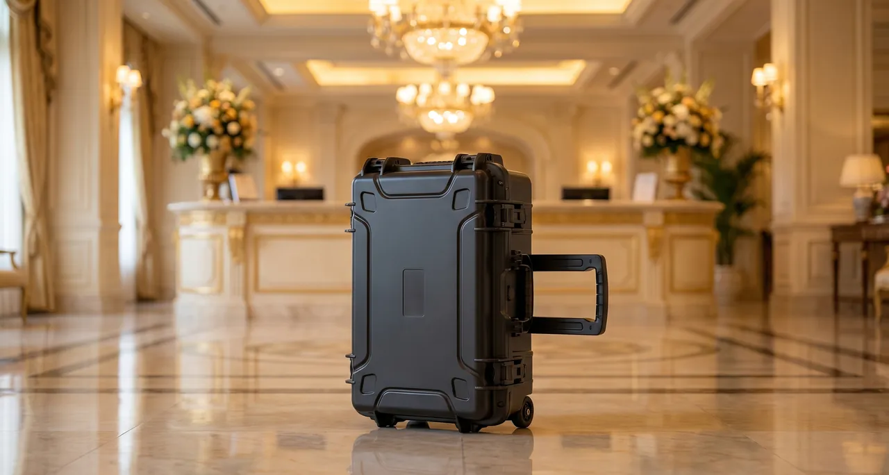
The test basis should match the real logistics route. The difference between ISTA 1A and 2A sets the intensity, domestic road and rail movements can reference the GB/T 4857 series, and ocean freight is better served by a distribution cycle that combines temperature, humidity and stacking. For related equipment contexts, see the Water Treatment Equipment Case Approach and Sludge Dewatering Equipment Cases.
Temperature, Humidity, Salt Spray and Test Basis
Temperature affects sewage equipment parts in two directions. Cold hardens rubber membranes, freezes water-filled modules and pushes some engineering plastics into their brittle range. Heat accelerates rubber ageing, worsens compression set in seals, and drives the relative humidity inside a closed case towards saturation. A shipment crossing climate zones, particularly a winter consignment moving from a cold region to a hot, humid one, can pass through tens of degrees within days, and the design must cover that whole curve.
Salt spray testing is the usual way to rank the corrosion performance of metal parts and coatings, normally as neutral salt spray under GB/T 10125 or ISO 9227, with acetic acid or copper-accelerated acetic acid variants used for acceleration when needed. It is worth stating clearly that salt spray testing ranks competing designs; it does not convert directly into field life and does not support a claim that a coating will last a stated number of years. Its value lies in comparing plating, coating, passivation and rust-prevention packing options on a like-for-like basis.
For sewage duty, hydrogen sulphide and microbial activity add a combined chemical and biological attack that standard salt spray work does not cover. What packaging can do is raise cleanliness, control humidity, add adsorption and inhibitor materials, and where necessary shorten the packing cycle and improve storage conditions.
Arrival Acceptance Checklist and Re-Inspection
The value of packaging is finally confirmed by arrival inspection. Sewage equipment has a particular difficulty: many defects, such as micro-creased fibres, scratched sealing faces and damp insulation, are invisible at the moment the case is opened, so inspection must follow a fixed sequence and be recorded.
The unpacking order is: observe the outer case, read the environmental indicators, open and inspect the liner, then remove and examine each part. If the outer case already shows deformation, a puncture or water staining, the shipment may have exceeded design conditions, and evidence should be preserved before opening. Environmental indicators include the degree of colour change on the humidity card and the state of the pressure valve, which are the first-hand data on whether the microclimate held. After removing a part, run a quick visual and dimensional check, then a category-specific check: membrane faces and potted heads for modules, membrane flatness and pore cleanliness for aerators, insulation resistance for machinery, and rust, white spots and dissimilar-metal contact for metal parts.
| Item | Check | Acceptance criterion | If abnormal |
|---|---|---|---|
| --- | --- | --- | --- |
| Outer case | Deformation, puncture, water marks, labels | Structure intact, marking legible | Photograph, assign responsibility |
| Microclimate | Humidity card, breather valve | Indication within limit, valve intact | Dry out and retest |
| Liner | Displacement, compression, fracture | Correct position, no set marks | Replace liner, re-verify fit |
| Membrane module | Faces, potted heads, headers | No hard crease or crack, ports sealed | Tag and isolate, inform supplier |
| Aerator | Membrane flatness, pores | No set, no oil blockage | Scrap part or replace membrane |
| Machinery | Insulation, oil chamber, cable | Insulation passes, no leak, root intact | Dry out or return for inspection |
| Accessories | Packing-list conformity | Quantity and specification match | Replenish and record |
Acceptance records should cross-reference the packing list and the packaging design number so the loop closes. For practical handover practice, see Filter Press and Dewatering Equipment Cases and the Diaphragm Pump Case Approach.
Model Selection Chart and Bespoke Flow
Applying the principles above produces a component-by-component selection table. It does not replace case-by-case assessment, but it narrows the design direction quickly.
| Component | Recommended case | Liner approach | Atmosphere and sealing | Key marking |
|---|---|---|---|---|
| --- | --- | --- | --- | --- |
| MBR module or cassette | Upright reinforced case with load beams | EVA form-fit cradle plus PE film | Wet wrap, freeze liner | Do not invert, freeze warning |
| Disc or tubular aerator | Flat reinforced case | Separate EPE or EVA pockets | Desiccant, clean inner wrap | No load, no oil |
| Ceramic diffuser | Compartment case | One part per soft pocket | Desiccant, damping | Fragile, shock protection |
| Blower | Heavy timber or composite case | PU base plus EVA stops | VCI and desiccant, sealed ports | Centre of gravity, lifting points |
| Submersible mixer or pump | Upright located case | Form-fit cradle plus cable pocket | Sealed, desiccant | Do not lift by cable |
| Valves, flanges, brackets | Standard industrial case | Divider panels, soft edges | Desiccant, VCI | Count against list |
| Online instrument | Precision instrument case | CNC EVA plus anti-static layer | Double seal, desiccant | Shock and moisture |
| Spares and fasteners | Accessory case | Compartment tray | Desiccant | List number matching |
A custom programme normally runs through six stages: requirement confirmation covering the component list, masses, dimensions, logistics route and climate; design covering case type, load structure, liner and compartments, sealing and environmental control; prototype verification with drop, vibration and stacking tests; small-batch trial production to fix moulds, liners and the packing work instruction; volume delivery with batch inspection and records; and arrival review that feeds site findings into the next revision. Both parties should sign off the key gates together, and in particular the wet or dry state of membrane modules, the oil condition of machinery and the on-site hoisting method, because those three are where responsibility most easily falls into a gap.
Kexin New Materials (Guangdong) Co., Ltd. designs and manufactures protective cases and can supply sewage treatment customers with custom liners, tooling, OEM/ODM production, printed identification and documentation including packing lists, humidity record cards and packing work instructions, turning packaging from a consumable into a traceable protection system. For customers who already have a packaging scheme, the thinking in Corrosion Resistant Enclosure Structures and Centrifugal Blower Transport Protection can be applied to optimise individual components.
Frequently Asked Questions FAQ
Q: Why do some MBR membrane modules have to travel wet while others can travel dry?
A: The answer depends on the membrane material and the preservation process agreed with the manufacturer. Hollow fibre membranes shrink when they dry out, and for some polymers, such as PES and PS, flux never recovers, so these modules travel immersed in water holding a preservative like sodium bisulphite or a glycerine-based blend. That liquid keeps the pores wetted, holds microbial growth in check and protects the fibre structure during storage and transit. Modules shipped this way must also have freeze protection, because expanding ice cracks fibres and potted heads. Other products, including many PVDF membranes and elements with special hydrophilic treatment, tolerate dry storage with little measurable loss, and dry shipping is lighter, easier to stack and simpler to handle on site. The choice is the supplier's to state in the technical agreement, and the packing design follows it. Wet packing has to solve wrap strength, retained liquid level and freezing point; dry packing has to solve humidity, high temperature and creasing. Never change the storage state on your own initiative when the agreement is silent, and always mark the state clearly on the case.
Q: What happens when aerator membranes stay compressed in the case, and how is it avoided?
A: A rubber membrane held under load for a long period undergoes stress relaxation and compression set, so the openings no longer spring back fully once the load is removed. Air distribution becomes uneven, oxygen transfer efficiency falls, blower energy rises and local tearing can develop over months of service. Three practical countermeasures prevent this. First, place each diffuser in its own pocket lying flat so membranes never stack directly on one another. Second, support the part over a broad area rather than at a few points, so no hard object presses into the membrane surface. Third, cap stacking height and storage duration so parts near the bottom do not carry the weight of everything above them for extended periods. Tubular diffusers need support at several points along the length and should stay straight, never bent. Disc diffusers should be packed with clamps, flanges and other metal items kept well away from the membrane face. On arrival, any membrane that recovers slowly, shows a fixed impression or feels stiff should be quarantined as non-conforming rather than installed, because the defect will not correct itself in service.
Q: What is the most commonly overlooked damage to submersible mixers and sewage pumps in transit?
A: The cable root and the mechanical seal are the two most frequently missed. Where the cable leaves the housing there is a dedicated sealing and clamping arrangement, and if the cable is used as a lifting point, or strapped tightly close to the root, the sheath kinks, the cores are strained and the sealing face distorts. Water then enters, the motor shorts, and nothing is visible when the case is opened. The second issue concerns the mechanical seal and the oil chamber. Inverting a unit, laying it on its side, or exposing it to sustained vibration lets lubricating oil migrate into the motor cavity or escape through the breather, contaminating every other part in the case and starving the seal of lubrication. The correct arrangement is a cable clamp that anchors the root, with the remainder coiled at a generous bend radius in its own pocket. The unit is fixed in its designed attitude, inversion is prohibited, and all oil ports and breathers are sealed before the case closes. The case should carry clear markings for attitude and a warning that the cable must never be used for lifting.
Q: Why does sewage equipment packaging emphasise cleaning and drying more than ordinary industrial packaging?
A: Sewage service leaves sludge, inorganic salts, sulphide-bearing deposits and biofilm on equipment surfaces, and inside a closed case those residues create a warm, saline, sulphide-bearing microclimate. Salts concentrate as moisture migrates and promote chloride pitting in stainless steel. Sulphides attack silver, copper and tin-plated contacts. Residual sludge ferments and produces odour, and the same fermentation releases hydrogen sulphide that accelerates corrosion of plated surfaces. The trouble is that this damage usually appears on arrival as nothing more than slight discolouration, then accelerates rapidly once the equipment is in service and the affected parts are difficult to reach. Parts should therefore be drained, rinsed, acid-neutralised where process deposits demand it, and thoroughly dried before packing, with a traceable cleaning and drying record attached to the batch. Welded grade 316L components that will see chloride exposure should have residual salt checked. For long sea routes, combine vapour-phase corrosion inhibitor materials with a correctly sized desiccant charge, and confirm that the case can hold the target humidity for the whole voyage. Cleanliness is part of the corrosion specification rather than a cosmetic step.
Q: IP65 or IP67, which case should a treatment plant choose for on-site storage?
A: Choose by exposure condition rather than by the apparent superiority of a higher number. IP65 is enough for hose washing, rain and short-term splashing, which covers on-site staging, in-plant transfer and normal road transport. IP67 tolerates short immersion, so it suits open yards that collect standing water, ocean crossings where green water can come over a deck, and containers that condense internally. It is important to remember that an IP rating describes only the enclosure's dust and water resistance. It says nothing about the microclimate inside and does not guarantee humidity control. Even with an IP67 case, fit a correctly sized desiccant charge and a humidity indicator card, and consider a pressure equalization valve wherever the shipment crosses large temperature or altitude differences. Repeated opening, seal ageing and uneven latch loading all reduce real performance below the nominal rating, so the plant should set inspection and replacement intervals instead of trusting the label indefinitely. Record which cases are opened most often and inspect their seals first, since those units are the most likely to let water in during the next trip.
Q: Can membrane modules and aerators travel in the same case?
A: It is not advisable unless strict physical and atmospheric separation is built into the design. The two families are sensitive to different conditions and can readily damage each other. Aerator bases, clamps and flanges are hard items that can scratch or crush a membrane face under vibration, while oil and corrosion products from machinery and metal parts clog diffuser pores and contaminate membrane sealing faces. If logistics genuinely force a shared case, apply three layers of separation. Divide the interior with independent compartments or an inner case, add a PE barrier film to block oil and dust migration, and control the microclimate with desiccant plus an adsorbent for odour and sulphide. Place heavy items over the floor load beams and stand membrane modules upright in a protected zone with their own cradle. Even then, separate cases remain the safer answer, and the packing list should state the rule explicitly so that handlers do not combine shipments at a transfer point. High-value, non-reworkable MBR modules should never travel with oily or rust-prone components.
Q: What is the most common cause of failure in transport testing?
A: In practice, the most common cause is not insufficient shell strength but inadequate liner and location design. Three patterns dominate. The first is resonant amplification, where the stiffness of the cradle sits close to the natural frequency of the packed part, so a frequency sweep amplifies the input several times and instruments lose calibration or bearings are damaged. The second is permanent liner compression, where stacking and vibration reduce foam thickness irreversibly, the part develops clearance inside the case, and a later impact drives it against the wall. The third is poor heavy-item placement, where a high centre of gravity or a position away from the structural beams sends bending directly into the liner and the part during lifting and stacking. None of these is easy to predict at the drawing stage, so prototype testing should never be skipped. When packaging is designed for a new component family for the first time, select the test programme that matches the real route, and feed every failure back into liner density, support method and fixing points.
Q: What stages does a custom sewage equipment case go through from requirement to volume delivery?
A: Six stages are typical. The first is requirement confirmation, covering the component list, individual masses and geometry, centre of gravity and lifting points, logistics route, transport modes, plus the storage state of membranes and the oil condition of machinery. The second is design, covering case type, load-bearing structure, liner materials and compartments, sealing method and environmental control. The third is prototype verification, where sample cases are built and run through drop, vibration and stacking tests to confirm that there is no resonant amplification, no permanent compression and no leakage. The fourth is small-batch trial production to freeze moulds and liners and to issue the packing work instruction and inspection sheets. The fifth is volume delivery with batch inspection and retained records. The sixth is arrival review, feeding site findings into the next revision. Key gates should be signed off jointly, especially responsibility at handover interfaces, so transit damage can be traced to a specific stage rather than becoming a dispute.
Conclusion and Related Reading
Sewage equipment protection is component-level risk management. Keep membranes wetted, unfrozen and uncreased, keep aeration elastomers resilient and their pores clean, keep machinery dry with cable roots anchored, and keep stainless surfaces free of chlorides.
Related Reading