

A stretch wrapper forces packaging engineers to deal with thin-walled large parts and precision motion components in the same shipment. Turntable diameters commonly run from 1,500 mm to 2,200 mm while the deck plate is only 8 mm to 14 mm thick. The surface condition of the rubber-coated rollers inside the film carriage pre-stretch assembly directly sets the stretch ratio and the flatness of the delivered film. Once the raceway of a slewing ring or a roller chain takes a dent, the machine greets the end user with rotational noise, positioning drift and offset film layers. In transit, the damage that generates claims is rarely a dramatic impact; it is slow plastic deformation, flattened roller surfaces and migrated contamination under sustained load - a turntable crowned by a timber block, a rubber roller flattened by a strapping band, a chain left to swing against a gear ring. Military-grade packaging philosophy is therefore the wrong reference point. The workable framework is four engineering rules: three-point support, load only on the stiffened rim, chamber separation by component family, and enclosure without compression. This article walks through turntables, slewing rings and chain systems, film carriage roller sets, mandrels and brake components, and columns and electrical gear, giving liner structures, material parameters, markings and receiving checks that can be pasted directly into a packaging specification.
Split shipping is the norm for this equipment. A standard machine leaves the factory as five to seven units: turntable, film carriage assembly, mast, base frame, control cabinet and an accessory case, with the slewing ring and gearbox sometimes packed separately. More units create two practical problems. Mixed handling raises the odds of a wrong lift or a wrong stack, and nobody on the loading dock can tell which crate may be stacked and which must never carry weight. Crews stack by mass, so the lightest and weakest crate, the film carriage, ends up at the bottom. The following sections judge risk first, then define structure, then control marking. They concentrate on the three failure modes that dominate warranty arguments: turntable deformation, roller surface crushing and raceway damage. Readers who also handle cartoning or bottle-filling equipment may find the same logic applied in component case protection for food packaging machinery.
Table of Contents
- Transport Risk Profile of Turntables and Base Frames
- Deformation-Resistant Packaging for Large Thin-Walled Turntables
- Chamber Separation for Slewing Rings and Chain Drive Precision Surfaces
- Non-Compression Packaging for Film Carriages and Pre-Stretch Roller Sets
- Surface Protection for Rubber-Coated and Film Guide Rollers
- Securing Film Roll Mandrels, Brake Assemblies and Tension Sensors
- Anti-Bending Support for Lift Columns and Tower Long-Stroke Parts
- Vibration and Moisture Protection for Cabinets, Drives and Sensors
- Compartmentalized Storage for Fasteners, Chains and Spare Parts
- Liner Material Selection and Cleanliness Control
- Markings, Shipping Documents and Receiving Inspection
- Reinforcement and Outer Case Design for Sea and Multimodal Freight
- Common Questions and Answers
- Conclusion and Further Reading
Transport Risk Profile of Turntables and Base Frames
The turntable of a stretch wrapper is a textbook large-diameter thin-plate part. On the two most common sizes, 1,650 mm and 1,800 mm, the deck is laser cut from 10 mm or 12 mm cold-rolled steel, edge-folded to a height of 60 mm to 80 mm, and stiffened on the underside by four to six radial ribs of 40 mm to 60 mm height. In the free state such a deck usually holds flatness within 1.5 mm per meter, which looks robust. The stiffness, however, lives almost entirely along the fold line and the rib lines. The central square meter behaves as an elastic plate, so a support placed under the middle converts stacking load or thirty hours of vibration into a bowl-shaped crown. On site this shows up as axial runout at the rim, mismatched film layers and torn bottom wraps.
Base frames and slewing ring seats fail differently. A base frame is a welded rectangular structure with ample stiffness, so the concern is a fork tine or a timber block pressing a suspended span and leaving a shallow pocket. A slewing ring seat is a machined face with flatness held to 0.1 mm or 0.2 mm, and any hard contact raises the mounting error. The two parts are frequently crated together, which is exactly the practice that causes trouble, because frame mass travels through the blocking into the deck plate.
| Risk | Trigger Condition | Immediate Consequence | Packaging Countermeasure |
|---|---|---|---|
| --- | --- | --- | --- |
| Uniform stacking bow | Two or three crates stacked at sea, upper mass landing on deck centre | Flatness out of tolerance, rim runout | Route upper load through tooling columns to the case floor; free the deck centre |
| Point indentation | Block, fork tine or timber pressing the deck centre | Local pocket, raised high spot | Move every support onto fold line or rib junction |
| Rim impact | Fork tine entering the crate against the folded edge | Curled edge, roundness lost | PE corner guards plus circumferential timber stops |
| Gear tooth damage | Exposed slewing ring gear ring struck by chain or tool | Tooth pocket, meshing noise | Wrap gear ring separately, bag chain off the machine |
| Condensation | Day-night temperature swing at sea | Pitting on machined faces, tacky rubber | VCI film, desiccant, pressure equalization valve |
The last row deserves emphasis because it is the least visible. A container leaving a warm yard and crossing cold water can shed several litres of condensate inside a sealed crate. Machined faces with a thin oil film are usually safe; unprotected black oxide or bare cast iron is not, and rubber rollers absorb moisture into the compound and turn tacky. Venting the crate through a pressure equalization valve while keeping a desiccant load inside is the standard answer, and the sizing logic is explained in pressure equalization valve selection.
Deformation-Resistant Packaging for Large Thin-Walled Turntables
This is the core of the whole exercise. The design goal is not impact resistance but resistance to sustained pressure, because a sea voyage of 25 to 40 days acts on the part for three orders of magnitude longer than any drop event.
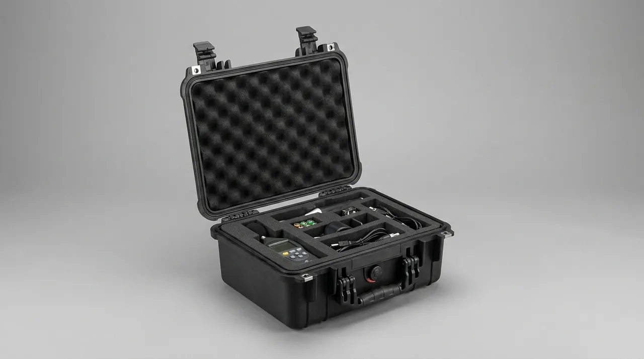
Rule one: supports belong on stiffened rib lines. Three-point support is the best answer because three points define a plane, so there is no situation where one leg lifts and the load concentrates on a diagonal pair. Place the three blocks where the folded edge meets a radial rib, with circumferential spacing no greater than 120 degrees, block width at least 80 mm, so pressure spreads along the rib instead of concentrating at a point. Four-point support is acceptable only when the deck carries equally spaced webs, and then shims of 1 mm to 2 mm must be available to level the set.
Rule two: the deck centre must be free. No block, timber or strap may pass through a central zone of 300 mm to 500 mm diameter. If the centre bore must be used for restraint, use a soft sling with a double washer of at least 120 mm diameter, and use the sling only to stop shifting, never to clamp the part down. Clamping a turntable to its base frame is the single most common error, because timber shrinks 1 mm to 3 mm as moisture content equalizes in transit, the strap goes slack and the part starts to move.
Rule three: route stacking load around the deck. When two decks must travel in one crate, install four steel or hardwood columns between them. The lower end of each column lands on the extension of the lower deck fold line, the upper end meets a bearing beam under the lid. The columns keep both deck faces entirely out of contact, and this is the only safe way to stack thin-plate discs.
For blocking, use EVA or XPE at 25 kg/m3 to 30 kg/m3 with Shore A hardness of 30 to 40. Harder foam leaves an imprint, softer foam loses its locating function. Wrap the rim with 40 mm PE half-round edge protection, then add a 15 mm plywood fence for circumferential restraint. Coat machined areas with a thin rust-preventive film, wrap the whole deck in VCI film, and add a woven fabric layer against abrasion. Build the pallet from plywood of at least 15 mm, with longitudinal bearers at no more than 800 mm spacing, so a fork cannot bow the floor between supports.
Chamber Separation for Slewing Rings and Chain Drive Precision Surfaces
The slewing ring is among the most expensive and least replaceable items on a stretch wrapper, and its raceway and gear teeth fall into the category of surfaces destroyed by a single impact. Leaving the ring bolted to the turntable for shipment looks efficient but compounds risk, because the exposed gear ring ends up facing chains, tools and timber blocking.
Correct handling is three-dimensional isolation. The first dimension is wrapping: wind the gear ring with 3 mm to 5 mm expanded PE sheet for at least two full turns and close both end faces with the same material. Never apply paperboard directly to a tooth flank, since paper sheds fibre that later works into a grease film. The second dimension is removal: take the roller chain off its sprockets and bag it in an oil-soaked woven sleeve inside a dedicated compartment. A chain left hanging is the worst possible state, because vibration turns it into a file that repeatedly rubs the tooth tips and can whip against machined faces. The third dimension is restraint: if the ring stays assembled to the turntable, place four hardwood wedges evenly around the circumference to limit radial movement. If the ring ships alone, sit its mounting face on a solid flat board, add a ring-shaped foam collar above, and let load act only on the ring end face rather than the raceway.
Chain and sprocket storage hides one more detail. The lithium-based grease applied at the factory becomes slightly fluid inside a hot container. Add an oil-absorbing nonwoven pad inside the chain bag and note on the parts list that the chain must be re-lubricated with the original grease grade after arrival, so the site does not substitute an incompatible product. For long-term storage of chain and sprocket assemblies, the same reasoning about rust prevention and contamination isolation used for hinge, latch and seal selection in toolboxes applies, because both cases are about protecting a working joint from moisture and grit.
Non-Compression Packaging for Film Carriages and Pre-Stretch Roller Sets
The film carriage is a cantilever frame carrying a precision roller train. Inside the vertical frame sit two pre-stretch rollers, typically one steel roller with chrome or ceramic coating and one rubber-coated roller, synchronized by a timing belt or a small gearbox with centre distance tolerance often held to plus or minus 0.2 mm. That centre distance fixes the stretch ratio, commonly between 150 percent and 300 percent, so a shift of even 0.5 mm in transit reappears on site as film wander and uneven gauge.
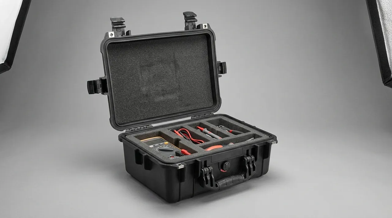
The first prohibition for the carriage is therefore do not compress it. Strapping bands, nylon rope and steel banding must never be tensioned across the carriage frame, because any external tension travels through the frame into the roller mounting bores and pulls the centre distance out of alignment. The correct approach is an enclosing cavity. Size the cavity 5 mm to 8 mm larger than the carriage envelope, line all four sides with 30 mm EPE or XPE, and shape the cavity floor to match the carriage underside so the assembly sits located rather than strapped. The goal is a part that does not move because it fits, not because it is tied down.
The second measure is modularization. Where the machine design permits, remove the pre-stretch roller set before crating and pack each roller in its own PE tube, leaving only the frame in the cavity. This change reduces crate height by 200 mm to 400 mm and removes the most expensive parts from the load path entirely. If the customer refuses disassembly, install a temporary rigid brace between the two bearing housings to prevent the timing belt from jumping teeth under vibration, and release the belt tensioner before shipment so the belt does not sit stretched for weeks. Tension is restored to the factory value on arrival.
The third measure is orientation and clearance. A film carriage must never be laid on its side or inverted, because side-laying transfers the assembly mass into one set of roller end bearings as shear. Spray "this side up" and "do not stack" on the outside of the case, and leave at least 20 mm of clearance under the lid so a loaded lid cannot press directly on a roller surface.
Surface Protection for Rubber-Coated and Film Guide Rollers
Rubber-coated rollers usually run at Shore A 40 to 60 with surface roughness of Ra 0.8 to 1.6 micrometres, and some designs add a diamond or herringbone pattern to raise friction. Three conditions destroy such a surface: sustained static pressure, plasticizer migration and sharp-edge abrasion.
Sustained static pressure produces irreversible compression set, commonly called a flat. A flat spot reappears as cyclic jitter and tension fluctuation during wrapping, cannot be compensated through machine parameters, and can only be cured by replacing the roller. Rubber rollers therefore belong to the same no-compression class as turntables and slewing rings. Slide each roller into a PE or PVC tube with an inner diameter 3 mm to 5 mm larger than the roller body and a wall thickness above 3 mm, close both ends with EPE discs, and separate parallel rollers with vertical dividers. Roller surfaces must never touch each other.
Plasticizer migration comes from cheap PVC tape and from foam made with recycled material. A plasticizer-bearing material left against a rubber surface makes the compound tacky, lowers hardness and can leave a stain that resists cleaning after a hot container voyage. Only PE, EPE, nonwoven fabric and aluminium-laminate film may contact a coated surface, and every pressure-sensitive tape must be applied to the outside of the packaging rather than to the roller itself.
Edge abrasion happens during handling, so corner guards and internal dividers need chamfered edges or PE edge strip. The table below maps roller types to protection level and receiving action, and can serve as an incoming inspection reference.
| Roller Type | Surface Sensitivity | Stacking Allowed | Isolation Material | Receiving Check |
|---|---|---|---|---|
| --- | --- | --- | --- | --- |
| Chrome-plated steel stretch roller | Medium, scratches and rust | Single layer, light load above | VCI film plus PE tube | Visual check for coating continuity and rust spots |
| Rubber-coated pre-stretch roller | High, pressure and plasticizer | Never | PE tube plus nonwoven wrap | Hand-roll the surface for flats and tackiness |
| Aluminium film guide roller | High, dents | Never | Expanded PE half-round cradle | Roll palm along surface to feel runout |
| Narrow film clamp roller | Medium, bending | Single layer, flat | Contoured EPE groove | Check straightness and end-face parallelism |
Securing Film Roll Mandrels, Brake Assemblies and Tension Sensors
The mandrel is structurally the simplest part of a stretch wrapper and the most often overlooked during crating. Common sizes take 76.2 mm or 152.4 mm cores, and the shaft carries a keyway, bearing journals and a tapered locking sleeve at each end. Precision concentrates on the two bearing seats, typically held to h6 or g6. A timber block pressed against those seats raises a burr, and the wound roll then runs with radial runout that produces serpentine film lay.
Pack the mandrel inside a paper or PE tube of matching bore, close both ends with EPE plugs, and seat it in a U-shaped timber cradle with cradle spacing no greater than one third of shaft length. For shafts longer than 1,200 mm, add a centre support to prevent permanent sag from self-weight.
Brakes and magnetic particle clutches are compound sensitive assemblies. A magnetic particle clutch redistributes its powder under strong vibration, which shifts initial torque; a friction brake with oil or moisture on the disc or pad loses repeatability. Pack them as separate items: rust-preventive film outside, 10 g to 20 g of desiccant inside, located in a non-load-bearing compartment, with a note in the specification forbidding drops above 300 mm. Tension sensors and load cells are usually strain-gauge devices, so they are shock sensitive. Keep them in the original antistatic bag with expanded PE cushioning; the groove layout and cushion thickness follow the same principles described in the custom foam insert design guide.
Anti-Bending Support for Lift Columns and Tower Long-Stroke Parts
The mast is the height-defining structure of the machine, typically 2,000 mm to 2,600 mm long, built from 100 mm to 150 mm square tube, with a chain or ball screw running inside. Its failure mode is narrow: bending. Above a slenderness ratio of roughly 40, self-weight and transport vibration combine to produce measurable mid-span deflection, which on site appears as jerky carriage travel and uneven guide wear.
The countermeasure is to convert one long span into several short spans. With three supports, keep the intermediate spacing at 900 mm or less; two supports suit columns shorter than 1,500 mm only. Support blocks should be U-shaped saddles matched to the tube section, formed from 30 mm to 40 mm XPE by heat pressing or lamination, with an R transition at the contact edge so the square corner does not concentrate stress. A column laid horizontally must have its web parallel to the support face; resting on a corner edge is unacceptable.
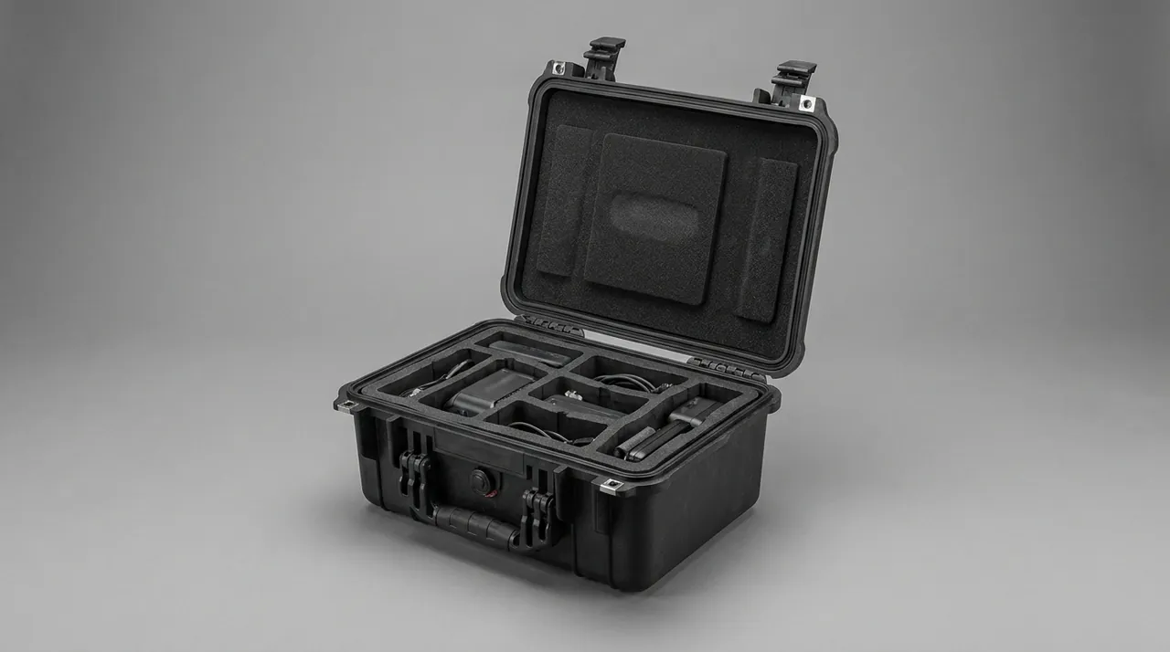
Rigging matters as much as blocking. Lift a column at the one-fifth and four-fifths points with flexible slings at least 50 mm wide, and never choke a square tube edge with wire rope. When the machine ships split, the best arrangement couples the mast into the same unit as the base frame, so the base acts as ballast and a rigid foundation and the long part never travels alone. If a separate long crate is unavoidable, keep the length-to-width ratio below 6:1 and add one internal cross partition as a second support. The support logic for long-stroke guide elements overlaps with guide rail and cylinder protection for lifting equipment, described in component case protection for hydraulic lift equipment, and the same spacing calculations can be reused with a simpler material set.
Vibration and Moisture Protection for Cabinets, Drives and Sensors
Electrical failures in transit are rarely caused by a hard drop. They come from vibration loosening connectors and from humidity lowering insulation resistance. A stretch wrapper cabinet usually houses a variable frequency drive, a PLC, contactors, breakers and terminal blocks, while the carriage carries roll diameter detection, tension feedback, limit switches and safety interlocks.
Inside the cabinet, place desiccant at roughly 25 g per cubic metre in two or three sachets, brace the door with a temporary strut so the latch is not loaded in shear, fit EPE corner guards, and sit the cabinet on a 20 mm rubber isolation pad. Restrain the cabinet in four directions with timber stops and do not place anything on top of it.
Remove electronic modules such as PLC cards, drive keypads and encoders, seal each in a shielded antistatic bag with desiccant, and place them in a compartmented box. Sensors belong in the precision category and should travel at vibration acceleration below about 1.0 g, a level consistent with the sweep and random vibration methods in the GB/T 4857 series. Add a shock indicator label when the route involves air freight or multiple transshipments, and treat any colour change as a trigger for functional retest on arrival. Machines destined for clean areas add a further constraint: liner materials must not shed, which is covered in the cleanliness section below.
One caution on moisture. Injection-moulded sensor housings sealed with gaskets protect against splash, not against a sealed crate full of condensate, so the crate-level solution of desiccant plus a pressure equalization valve matters more than the sensor's own IP rating. The relationship between sealing, venting and internal humidity is discussed in waterproof case construction at IP rated levels.
Compartmentalized Storage for Fasteners, Chains and Spare Parts
The accessory case looks trivial and generates a disproportionate share of site complaints. Mixed bolts, missing washers and a chain one link too short all delay commissioning by hours or days.
Organize storage by three compartments. The first holds fasteners grouped by assembly location, such as base anchors, mast connections, carriage mounting and guard fixing, each bag carrying an identifier that matches the parts list, with five percent quantity margin on each size. The second holds drive parts, including the removed chain, sprockets, timing belt and tensioner, all bagged in oil with the grease grade marked. The third holds wear spares, such as proximity switches, limit switches, a spare coated roller, seals and bearings, each in its own vibration-isolated bag.
Use injection-moulded plastic boxes or reinforced corrugated dividers rather than sponge, because sponge sheds particles under vibration and those particles end up inside sensors. Heavy items such as gearboxes and sprocket sets must sit directly on the case floor rather than suspended above a compartment box. Press every box fully into position and leave a 10 mm to 15 mm cushion layer above so boxes cannot hop vertically when the lid is closed. For small-part organization with removable dividers, refer to the EVA foam insert custom process and removable divider systems for protective cases.
Liner Material Selection and Cleanliness Control
Stretch wrappers are frequently installed in beverage, food and personal care lines, where liner cleanliness carries more weight than in general industry. GB 14881 and food GMP rules address contamination in exposed product zones. Packaging liner does not touch product, but a liner that sheds visible debris during opening creates a foreign-body risk, so the selection filter is low shedding, no plasticizer, no chlorinated compound and verifiable by visual inspection.
| Material | Density or Hardness | Cushioning Behaviour | Cleanliness | Typical Application |
|---|---|---|---|---|
| --- | --- | --- | --- | --- |
| Cross-linked EVA foam | 25 to 35 kg/m3, Shore A 30 to 40 | Medium to high, slow recovery | Low shedding, washable | Turntable blocking, shaped cavities |
| Chemically cross-linked XPE | 30 to 45 kg/m3 | High, resists repeated compression | Low shedding | Long-part saddles, edge guards |
| EPE pearl foam | 20 to 30 kg/m3 | High for single impact | Moderate, friable edges | General void fill |
| Solid PE sheet or tube | 0.5 to 0.95 g/cm3 | Low | Very low, smooth skin | Roller sleeves, dividers |
| Nitrile or EPDM pad | Shore A 50 to 70 | Good vibration damping | Low, confirm no sulfur bloom | Cabinet base isolation |
| Corrugated honeycomb board | Depends on grammage | Low | High shedding risk | Outer dividers only, never on clean machines |
A practical screening test costs nothing. Cut a sample of the candidate foam, flex it twenty times by hand, then tap it over black card stock. Visible white debris on the card rules the material out for a clean-area machine. JUNZHIJIA applies this filter when building component cases for food-grade wrapping lines, restricting liners to EVA, XPE and solid PE, and shipping a material list with low-shed test records so the buyer can verify at goods-in. A single machine also has conflicting internal requirements: the turntable needs load capacity, the carriage needs conformity, and the mast needs creep resistance, so using one foam grade throughout a crate is rarely the right answer.
Markings, Shipping Documents and Receiving Inspection
Markings are the packaging engineer's only silent representative on the dock. Following GB/T 191, every component case should carry this side up, keep dry, do not stack on the carriage and roller cases, centre of gravity, lifting points, and case number with total count such as 3 of 7. Carriage cases also warrant a "do not tilt beyond 30 degrees" instruction, because tilting lets the roller train shift inside its cavity.
Ship four document sets inside a waterproof bag fixed to a visible position: a packing list with case numbers and matched components, a parts and accessory list with bag identifiers, a packaging specification covering liner materials, support positions and stacking limits, and material certificates and inspection data for key items such as the slewing ring, coated roller and mandrel. JUNZHIJIA can add cushioning design calculations and a non-conformance handling flow on request, so the buyer can file them in a supplier audit package.
Receiving inspection runs in three stages. Before opening, check the crate skin and any shock or tilt labels. After opening, perform static checks: measure turntable flatness with a straightedge and feeler gauge against the 1.5 mm per metre reference, roll a palm along each rubber roller to detect flats and tackiness, inspect the slewing ring gear ring for pockets, and check column straightness with a taut line while the part is still unrestrained. Before reassembly, verify fastener counts and chain length. Any deviation should be photographed and assembly paused, because once parts are mounted it is nearly impossible to establish who caused the damage. Test methods and severities are set out in transport package testing under GB/T 4857 and in ISTA transport testing procedures.
Reinforcement and Outer Case Design for Sea and Multimodal Freight
Case geometry follows the aspect ratio of the part. Turntables suit a low, wide framed crate under 500 mm high with a slatted bearer floor that allows fork entry from both sides. Columns suit a long narrow crate with two internal cross partitions. Film carriages and roller sets suit dedicated cases with contoured liners and explicit do-not-stack marking on all four faces.
Four reinforcement actions cover most sea shipments. First, apply secondary restraint to every movable item using straps, wedges and retaining boards. Second, brace case against case inside the container with cross-set timber or longitudinal battens so a row cannot topple in heavy roll. Third, build a moisture barrier using PE film of 0.08 mm or thicker, or aluminium-laminate film, with desiccant at 25 g to 50 g per cubic metre and a pressure equalization valve so temperature swings do not create negative pressure that draws damp air inward. Fourth, add anti-slip material under the case floor, using rubber pads or anti-slip battens, targeting a friction coefficient of at least 0.4.
Multimodal routes add a second handling cycle, typically rail to sea, and the transshipment point is more likely to handle crates roughly than the origin port. Fit shock indicator labels to the crate and specify a level able to survive a 1.2 m drop on corner, edge and face. When aligning with ISTA 3E or an ASTM D4169 distribution cycle, set test intensity from the agreed assurance level rather than defaulting to the maximum, because overbuilding cushioning inflates volume and freight cost. Cushioning typically accounts for 15 to 25 percent of total packaging cost on this equipment class, and that is a line item worth balancing rather than maximizing.
Common Questions and Answers
Q: Does the turntable have to ship in its own crate, or can it travel with the base frame?
A: Combined crating is allowed when two conditions are met. First, each of the three or more turntable supports must land on a rigid node of the base frame rather than on the deck centre, ideally through locating brackets welded or bolted to the frame so the deck is held face-to-face or back-to-back. Second, every protrusion on the frame, including bearing seats, motor mounts and bolt heads, must be clear of the deck footprint or buffered by EVA strip at least 30 mm high so point contact becomes line contact. The residual risk of combined crating is higher gross mass, which invites rougher forklift and crane handling, so keep the combined crate below about 1,200 kg and split the shipment above that. Regardless of the arrangement, a central zone of 300 mm diameter on the deck must remain free, and stacking load must travel through dedicated tooling columns from case floor to lid bearing beam. That is the only safe compression path for a thin-plate disc, and it is the detail most often omitted when two units are packed together to save a container slot.
Q: A rubber-coated roller shows a slight flat. How do we decide whether it is still usable?
A: The decision depends on flat depth relative to machine requirements. Place a 0.1 mm feeler blade on the surface, bridge the depressed zone with a straightedge, and measure the maximum gap. A gap under 0.1 mm with no perceptible step is generally acceptable for a low-speed wrapper, and the machine can be run at reduced speed for thirty minutes while tension stability is observed. A gap above 0.2 mm, or any depression the hand can feel as a distinct hollow, means replacement. Compression set in rubber does not recover, so a flat produces one tension spike per revolution, creating a regular tight-loose pattern between film layers and accelerating fatigue in the timing belt and bearings. Prevention is far cheaper than judgement: sleeve each roller in its own PE tube before crating, forbid any strapping band from touching a coated surface, prohibit stacking of roller cases, and record incoming Shore A hardness with a retest trigger whenever the reading drifts more than five points from specification. Air freight deserves extra care because low temperature hardens the compound and increases crushing risk.
Q: What centre distance deviation is acceptable for a pre-stretch roller set after transport?
A: Production machines are designed around plus or minus 0.2 mm. After transport, remeasure with an inside calliper or a dedicated gauge and accept the assembly while deviation stays within plus or minus 0.3 mm. Above plus or minus 0.5 mm, investigate three candidates: deformation of the carriage mounting bores, a jumped timing tooth or a crushed tensioner during transit, and inward distortion of the frame caused by over-tensioned strapping. The more important distinction is between static dimension and dynamic film delivery, because a compliant centre distance still delivers a drifting stretch ratio if belt tension has moved away from the factory value. Restore belt tension to specification, turn the rollers by hand to confirm synchronized rotation without tooth jump, and run fifty metres of film with no load while watching for lateral wander. Without a tension gauge on site, use a synchronization mark: draw one aligned reference line across both rollers, rotate two full turns by hand, and check whether the lines still align as a coarse verification.
Q: What extra protection is needed if the slewing ring ships assembled to the turntable?
A: Four layers. Wrap the gear ring completely with 3 mm to 5 mm expanded PE sheet for at least two turns and close the end faces; never let paperboard touch a tooth flank. Remove the chain from the sprockets, bag it in oil and fix it in a dedicated compartment so it cannot swing against the teeth or whip across machined faces. Place four hardwood wedges evenly around the circumference to limit radial movement, with a 5 mm rubber pad between each wedge and the ring outer diameter so hardwood never presses directly on the ring. If the turntable is laid flat in the crate, orient the ring mounting face toward a solid board over a 10 mm rubber pad so load distributes across the ring end face rather than the raceway, and never let the ring bridge another component. On arrival, rotate the inner ring by hand and listen; a periodic click or a gritty hiss calls for disassembly and inspection. For voyages longer than forty-five days, add VCI film inside the crate and record humidity at opening.
Q: How should vibration limits be set for control cabinets and sensor items?
A: A practical target is to keep in-crate vibration acceleration below about 1.0 g, a level most industrial control hardware tolerates over long exposure, and to verify it using the random vibration and sine sweep methods described in the GB/T 4857 series. Achieve it in three tiers. The first is damping, using 15 mm to 20 mm rubber isolation pads at Shore A 50 to 60 or a laminated EPE pad under the cabinet base. The second is restraint, with timber stops on all four sides and gaps held under 5 mm so the cabinet cannot lift and land. The third is separation, moving removed PLC cards, drive keypads and encoders into shielded antistatic bags inside individual cushioned boxes rather than sharing a compartment with metal parts. Watch for false fixing: filling gaps with foam alone is not restraint, because compressed foam rebounds and pushes the cabinet into motion, so timber stops and foam must be used together. Before applying power after arrival, inspect terminal blocks for displacement, connectors for partial withdrawal, and safety curtains and limit switches for deformation.
Q: How is liner cleanliness specified for a stretch wrapper installed in a food plant?
A: The objective is to control shedding and chemical migration rather than to sterilize anything. Enforce three hard lines. Liner materials must exclude corrugated honeycomb, sponge and recycled-content foam, all of which shed heavily. Materials touching coated rollers, roller surfaces and machined faces must be free of plasticizer, which limits contact materials to PE, EPE, EVA, XPE, nonwoven fabric and aluminium-laminate film. The customer must be able to open the crate and visually confirm that no loose debris is present, so the packaging specification should name the material and its density. GB 14881 and food GMP rules aim at preventing foreign bodies from entering product, and within the logistics chain the effective control points are traceable material, low shedding and a controlled opening procedure. In practice, request a material list and low-shed test records from the supplier, and add a white-paper wipe to the receiving checklist: wipe the liner surface ten times with white paper and look for visible particles. JUNZHIJIA restricts liner materials to the customer's cleanliness class and ships the corresponding documentation with the crate.
Q: How should the packaging level change between transport modes?
A: Adjust for handling frequency rather than distance. Air freight and express involve the most handlings, so specify a 1.2 m drop capability and fit shock indicator labels. A direct full-container sea shipment involves the fewest handlings and can be designed to a 0.8 m to 1.0 m drop level, with the engineering effort shifted to moisture control and long-term compressive creep. Rail and less-than-truckload road freight sit between the two, where the priorities are vibration control and reinforcing the lifting points that will be used repeatedly. Three variables carry the adjustment: cushion layer thickness, outer frame stiffness and internal restraint strength. Most mismatches run in the wasteful direction, where a short domestic delivery receives air-freight-grade packaging, inflating volume and cost. The opposite error also happens, and a minimum-grade crate on a less-than-truckload route typically shows frame cracking after the first transshipment. Document three standard packaging levels, let the buyer select one at quotation, and note the selection on the packing list so that label discolouration on arrival can be judged against a known design envelope.
Q: The turntable arrives with flatness out of tolerance. How do we tell manufacturing from transport?
A: Distinguish by deformation geometry and trace evidence. Pressure deformation in transit normally appears as a local high spot with adjacent sagging, aligned with a block, fork tine or strapping location, while the liner often carries a matching imprint at that point. Deformation from manufacturing residual stress shows as a regular wave along welds, with continuous undulation near rib toes. Collect evidence by measuring and photographing flatness with the part still unrestrained, preserving the liner, recording dents or fork marks on the crate, and checking shock and tilt indicators. Where the crate is intact, labels unchanged, and the liner imprint aligns with the high spot, transport responsibility is the likelier conclusion. Where the crate shows no sign of load, the balance shifts to fabrication or heat treatment. Record flatness before shipment with the measurement attitude stated, and ship the inspection record inside the crate.
Conclusion and Further Reading
Crating a stretch wrapper is about pressure and contamination control, not shock. A thin-plate turntable needs three-point support on rib lines. A pre-stretch roller set needs enclosure without compression. Slewing rings and chain systems need chamber separation. A mast needs multiple supports. Map those four rules onto liner structure, support position, restraint method and crate marking.
Further Reading