

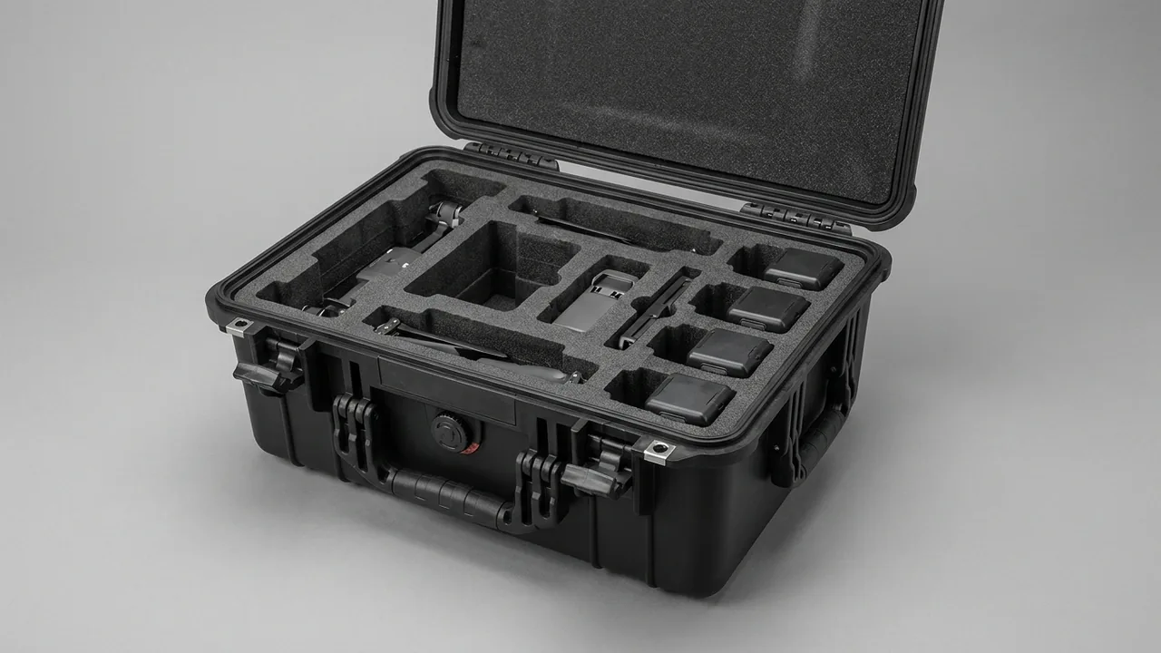
Conclusion first: the carton forming mold and suction cups of a cartoning machine are no-contact surfaces and the pusher rod is a no-bend component, and failure of either kind does not stop the line immediately but slowly amplifies as rising jam rates, skewed fold creases and scored cartons; protection in transit therefore has to preserve shape, cleanliness and straightness rather than simply resist impact. JUNZHIJIA supplies component cases for carton forming stations, pusher mechanisms, cam transmission boxes and sensing and control units that meet the cleanliness expectations of GB 14881 and GMP, covering custom compartmented liners, model-matched vacuum cups and gaskets, and acceptance documents travelling with the case.
When a cartoning line is expanded, rebuilt for a new carton format or moved to a new plant, the losses that hurt most come from parts that "fit but do not run right". A scuffed carton-blank suction cup makes pick-up unreliable and raises the drop rate, yet operators usually adjust vacuum pressure first and overlook that the cup itself has deformed. A pusher rod squeezed laterally in transit takes a slight bend; once installed, the push path drifts and products no longer enter the carton squarely, leaving score marks on the carton ends. A cam box shaken over a long haul lets its grease migrate to one side, producing noise and intermittent hesitation during the first hours of running. This article follows the two main threads of carton forming and product pushing, sorting cartoning machine components into four sensitivities - impact, bending, contamination and magnetism - and sets out packing, liner, transport and arrival acceptance methods that can be executed as written.
Table of Contents
- Why Cartoning Machine Parts Need Dedicated Cases
- Carton Forming Station: No-Contact Rules for Forming Molds and Suction Cups
- Pusher Mechanism: Pusher Rod Straightness and Guide Protection
- Transport Protection for Cam Mechanisms and Transmission Boxes
- Vibration and Static Protection for Sensors and Control Units
- Vacuum System: Cups, Air Lines and Filter Elements
- Paper Dust and Contamination Control: Cleanliness Design (GB 14881 / GMP)
- Compartmented Liner Layout and Cushioning Structure
- Case Sealing and Internal Micro-Environment Control
- Lifting and Fixation of Base Plates and Frame Assemblies
- Transport Testing and Packaging Marks (ISTA / GB/T 4857 / GB/T 191)
- Selection Parameter Comparison Table
- Custom Liners and OEM/ODM Delivery
- On-Arrival Unpacking and Acceptance Workflow
- Common Questions FAQ
- Conclusion and Related Reading
Why Cartoning Machine Parts Need Dedicated Cases
A cartoning machine places bottles, tubes, blister cards or pouches into folded cartons on the secondary packaging end of food, personal care and pharmaceutical lines, typically cycling dozens to several hundred cartons per minute. The higher the cycle rate, the tighter the tolerance of every motion, and the more the components depend on *shape*. A suction cup must sit flat against a carton blank to pick it reliably, a forming frame must be geometrically square to press a crisp crease, and a pusher rod must remain straight along its whole length to slide a product into the carton cavity without skew. All three requirements point to the same demand: the part must leave the factory in the geometry it had when it was inspected.
Unlike heavy equipment that carries high loads, cartoning components suffer mostly from low-energy, cumulative damage. One modest squeeze during transport is enough to bend a long cantilever pusher rod by 0.5 mm, a deviation that is almost invisible in a static measurement but magnifies into several millimetres of path error at the end of the stroke. A tiny rolled lip on a suction cup is equally silent: it does not fail at once, it simply lengthens the time needed to build vacuum, and the symptom finally appears as occasional dropped cartons at high cycle rates. Damage happens in transit while the loss surfaces in production, so a dedicated case exists to move the quality decision forward to the moment of dispatch.
JUNZHIJIA positions cartoning machine protection as one stage of the equipment delivery chain. The case must survive repeated transfers with the machine, the liner must locate every part by its own outline, and the sealing and lifting hardware must meet reusable standards. The generic selection logic behind that reasoning is set out in plastic protective box; the sections below work through the cartoning machine station by station.
Carton Forming Station: No-Contact Rules for Forming Molds and Suction Cups
The carton forming station consists of the blank magazine, pick-up suction cups, the forming frame or forming mold, the tuck-in mechanism and the carton compression assembly. A blank is drawn from the magazine by the cups, enters the forming frame, has its side panels folded and pressed into shape by the tuck-in mechanism, and is then handed to the main chain by the pusher. Two traits are shared by the parts here: they rub continuously against board, and their geometry directly determines crease quality.
The forming frame is usually machined as one piece from aluminium alloy or stainless steel, with rounded or chamfered corners in its cavity that guide the carton as it opens. Its no-contact surfaces are the working corners inside the cavity and the top rim, because a single knock there leaves a matching pressure mark on every carton that passes through. JUNZHIJIA uses an upright, cavity-clearanced liner design for forming frames: the frame stands in its own compartment with EVA foam locating it on all four sides, a clearance pocket above the cavity so the working corners touch nothing, and paired frames in separate compartments with nesting strictly forbidden.
Suction cups are the most casually treated parts at this station. A cup is moulded from rubber or polyurethane with a lip typically 0.5-2 mm thick, and its sealing ability depends entirely on the lip holding a true contour in a free state. Three rules govern their protection. First, place each cup in a foam pocket machined to its lip outer diameter, with pocket tolerance held within 1 mm so the cup cannot rattle and rub. Second, never mix cups with metal parts in one compartment and never stack them on each other. Third, cold conditions raise rubber hardness and slow rebound after compression, so winter shipments need insulation inside the case and cups should stand at room temperature for 24 hours before unpacking. On bellows cups the corrugated section concentrates stress, so it must travel free of load rather than compressed.
Pusher Mechanism: Pusher Rod Straightness and Guide Protection
The pusher mechanism drives formed cartons or incoming products along a straight path into the next station and is the most geometry-sensitive assembly on a cartoning machine. It normally comprises the pusher rod or pusher plate, a guide bushing, a guide shaft, a mounting block and a drive linkage. Pusher rods are long, slender cantilevers that can reach several hundred millimetres in length with a diameter of only ten to a few tens of millimetres, and that slenderness means the load they tolerate least is lateral, not axial.
Straightness is the acceptance criterion for a pusher rod. As a rule of thumb, a 500 mm rod bent by 0.3-0.5 mm can already produce a visible path deviation at the end of the stroke once installed, and that deviation causes three problems: carton faces get scored during insertion, the pusher plate and guideway wear unevenly, and periodic vibration and noise appear at high speed. The classic causes of bending in transit are a rod laid across the case floor with something heavy on top of it, a strap tightened directly around the middle of the rod, and the rod being used as a lever or handle during loading.
JUNZHIJIA protects pusher rods by cradling the full length, supporting it at many points and keeping it free of load. The rod lies horizontally in the liner on V-shaped or U-shaped supports spaced no more than 150 mm apart, so its self-weight deflection is shared among many contact points. The body is sleeved in soft non-woven fabric, and threads and keyways at both ends receive protective caps. Nothing may be laid on top of a rod inside the case. Where a pusher assembly ships pre-assembled, keep the bushing and guide shaft in their fitted relationship, because stripping them down and reassembling them on site introduces a fresh concentricity error.
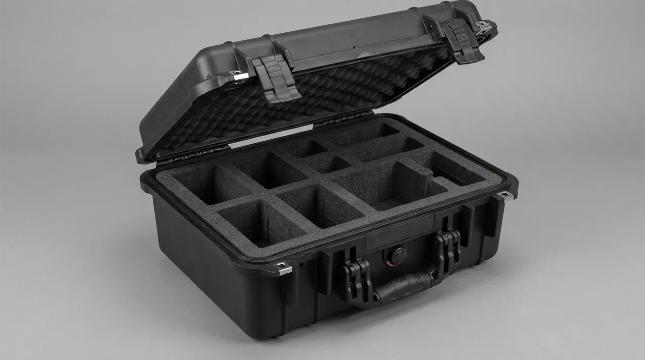
Guide bushings and guide shafts are sliding or rolling fits, and if they move freely in transit they strike their end stops repeatedly and score the bore. Tie the guide assembly at the middle of its stroke with a nylon cable tie, place a soft pad under the tie, and on arrival cut the tie before working the assembly back and forth by hand to confirm it runs smoothly with no hard spots before power is applied. General approaches to compartments and stops are described in the removable divider system article.
Transport Protection for Cam Mechanisms and Transmission Boxes
Medium and high speed cartoning machines commonly use cam mechanisms and indexing boxes to synchronise several stations, and the interior of a cam box contains conjugate cams, roller followers, output shafts and gear sets running in a measured charge of grease or oil. Three transport risks apply: relative micro-motion between internal parts producing marks on the roller and cam faces, lubricant migrating to one side under tilt or vibration, and damage to exposed shaft ends and keyways.
Controlling the first risk means restraining free rotation of the input and output shafts. Before casing, lock the output shaft with a rigid coupling clamp or a dedicated locking block so long-haul vibration cannot make the roller hammer the cam face repeatedly through a small arc. For a cam box that is already assembled and greased, record the grease grade and the oil level mark, and keep the housing in its normal installed attitude with inversion forbidden. If the box must lie on its side, note it in the packing documents and specify a settling time on arrival so the lubricant can flow back before power-up.
Exposed shaft ends, flange faces and oil seals form the second priority. Fit plastic guards over shaft ends, apply protective film to flange mounting faces, and cap seal lips so dust cannot lodge there and cause early leakage. A cam box shipped without grease needs its interior sprayed with rust preventive and every breather plugged, since moisture entering the housing will form rust on the cam faces, and rust on a cam face changes the follower motion curve directly.
Storage carries its own rules. Transmission and cam boxes must not be stacked or used as a shelf, because deformation of the housing changes the preload state of the internal bearings. During long storage, turn the box over by hand a few revolutions each quarter so the grease redistributes across the working faces of the cam instead of leaving a dry contact patch. Combining this routine with the general interval advice in protective case service life keeps the whole storage cycle consistent.
Vibration and Static Protection for Sensors and Control Units
The sensing system of a cartoning machine includes photoelectric switches checking blank magazine level, proximity switches confirming cup pick-up, encoders measuring pusher travel, fibre-optic amplifiers detecting missing cartons, and door interlock switches. The control side includes servo drives, PLC modules and touch panels. These parts are function-sensitive rather than geometry-sensitive: they can look perfect and still count as transport failures through parameter drift or internal component damage.
The main risks for photoelectric and fibre-optic sensors are a scratched optical window and a shifted optical axis. Put the sensor body in its own anti-static foam pocket with the optical window facing up or to the side away from any rubbing surface. Pack fibre heads and fibre cables separately, and coil the cable at a diameter no smaller than ten times its minimum bend radius, because a tight bend inside the case creates permanent attenuation. The sensing face of a proximity switch must not touch metal directly; a layer of insulating foam belongs between them.
Static and vibration dominate for encoders and servo drives. Charge accumulated in transit can puncture interface chips, so use anti-static bags or conductive foam and lead the grounding terminal out through the case wall, following the requirements in the ESD shielding case solution. Mounting faces and shaft ends are fits, so apply protective film and fit shaft-end guards to prevent concentricity errors from knocks. Touch panels need protection against compression as well: cover the screen with film, place it screen up, and allow no load above it.
One reminder matters more than any other here. Control components should pass appearance and insulation checks before first power-up, and the factory parameter backup should travel in the case. Servo parameters and cam curves on a cartoning machine usually have to correspond exactly to mechanical phase, and losing them costs far more site time than the packaging ever saved.
Vacuum System: Cups, Air Lines and Filter Elements
Carton pick-up and carton opening rely on vacuum, produced and controlled by a vacuum generator or pump, a vacuum filter, solenoid valve manifolds, vacuum lines and suction cups. Two classes of risk apply in transit: contamination inside the air path and deformation of sealing components.
The rule for vacuum lines is to plug both ends and never leave a bore exposed. Blow each line clean before casing, fit plugs or heat-shrink caps at both ends, and coil flexible hose at a bend radius no smaller than fifteen times its inner diameter so a long-term tight bend cannot flatten the bore. A flattened hose looks intact but reduces flow noticeably. On assemblies with a vacuum filter, confirm the element is seated or pack it separately, and state the installation direction in the packing documents so nobody fits it backwards and loses suction.
Vacuum generators and solenoid valve manifolds are precision pneumatic parts with spool clearances often measured in micrometres, making them highly dust-sensitive. Bag the whole assembly in an anti-static dust bag before placing it in the liner, cap every port, and never let it share a case with uncleaned parts. Before connecting the assembly on site, blow the lines through with dry compressed air so no residual dust reaches the spool and jams it.
Suction cups appear again here because their condition depends on both the vacuum system and their own geometry. When a lip is rolled or cracked, the system takes longer to reach vacuum, and the usual reaction is to raise the vacuum level, which accelerates wear on both cups and pump. Arrival acceptance therefore has to check every cup individually, running a fingertip around the lip to feel for hard spots and defects, with a rebound check added in cold weather. On-site inspection practice follows the principles in how to clean a protective case.
Paper Dust and Contamination Control: Cleanliness Design (GB 14881 / GMP)
A running cartoning machine generates paper dust from fibres shed at the cut edges of blanks, fragments rubbed off during folding and tucking, and debris accumulating on the conveyor. When the machine serves food or pharmaceutical secondary packaging, that dust affects motion and also represents a foreign-body risk, so the transport packaging of its components has to match.
Food production references GB 14881, the general hygiene regulation for food production, for requirements on packaging and contact materials; pharmaceutical production is governed by GMP and may cite the ISO 14644 series for airborne particle classification. Four requirements follow for cartoning component packaging. First, materials that shed particles, including wood wool, straw and shredded paper, are forbidden as filling because they release fibres into the cleanroom the moment a case is opened. Second, parts that touch cartons - the forming frame cavity, the working end of the pusher plate and the suction cups - belong in cleanroom bags, with unpacking done in the airlock. Third, liner material must be closed-cell and non-shedding so foam debris cannot remain in a forming frame cavity. Fourth, no sulfur-bearing or chlorine-bearing material may touch stainless steel directly, since damp conditions make such compounds promote pitting.
The table below lists the cleanliness packaging grades JUNZHIJIA recommends for different cartoning machine components.
| Contact category | Typical components | Cleanliness packaging required | Recommended liner material | Grade |
|---|---|---|---|---|
| --- | --- | --- | --- | --- |
| Direct contact with product or carton cavity | Forming frame cavity, pusher plate working end | Cleanroom bag plus lint-free wrap | Closed-cell EVA | Grade A |
| Direct contact with carton surface | Suction cups, carton compression assembly | Individual pockets plus cleanroom bag | Closed-cell PE or polyurethane foam | Grade A |
| Inside cleanroom but not contacting | Photoelectric sensors, fibre optics, guides | Anti-static bag plus dust caps | EVA plus anti-static foam | Grade B |
| Outside cleanroom | Cam boxes, base plates, frame parts | Anti-rust plus dust protection | PE pearl foam | Grade C |
For pharmaceutical customers who must validate equipment, state the liner material and cleanliness treatment in the delivery documents so the packaging step can be filed with the validation records. A comparable scenario is described in the food packaging machinery case article.
Compartmented Liner Layout and Cushioning Structure
Cartoning machine components span a wide range, and a single machine carries both parts weighing a few tens of grams and base plate assemblies weighing more than a hundred kilograms. That spread rules out a single material or a single pocket shape; the liner has to be combined by weight class and by contact category.
JUNZHIJIA applies four rules when choosing liner material for cartoning parts. Precision working faces and elastic parts get closed-cell EVA for conforming location. Long rod parts get PE pearl foam combined with multi-point cradling to spread self-weight. Control and sensing parts get anti-static foam in isolation. Heavy base plates get high-density PE or a timber frame with rubber isolation pads underneath. The underlying principle is a soft contact face, a hard support face, locked moving parts and tightly filled voids.
Pocket layout should follow function rather than volume. A sound arrangement puts carton forming, product pushing, vacuum and pneumatic parts, and control components into four separate zones, each with its own parts list; components of one zone share a packing diagram, so the receiving plant can open and assemble zone by zone and avoid mixing parts. This compartment approach follows the modular separation described in the removable divider system article, with the difference that cartoning machine pockets must be machined to the part outline rather than merely divided by flat panels.
Layering by weight matters just as much. Heavy parts go at the bottom on their own load-bearing structure; light and precision parts go above; a rigid divider separates the layers so upper foam never presses directly on a lower component. Small items such as suction cups can have their own pocket beside a heavy part, but a rigid barrier must sit between the small pocket and the heavy part so movement of the heavy item cannot squeeze the small one.
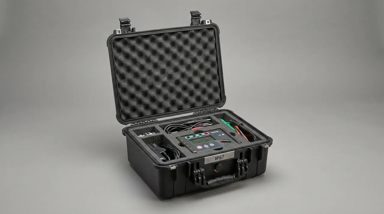
The goal of cushion design is to hold peak acceleration below what the part tolerates under a standard drop, not simply to add foam. In practice, permanent compression set of a cartoning machine liner should stay within 15 percent; beyond that the pocket has lost its locating function and the pocket should be replaced rather than reused.
Case Sealing and Internal Micro-Environment Control
When cartoning machine components are exported or transferred between regions, humidity and temperature swings along the route are the main disturbance to the internal environment. Once a cleanliness-critical part takes on moisture, thin rust or water marks form in a forming frame cavity, on a pusher plate working face or along a stainless guide shaft, and even where function is unaffected the part is rejected at incoming inspection and has to be reworked. Case sealing and internal humidity control therefore need planning rather than improvisation.
JUNZHIJIA ships cases that typically meet IP67 under IEC 60529 / GB/T 4208, giving full dust tightness with short-term immersion protection for rain transfer, flooded docks and deck spray at sea. For coastal routes with heavy salt spray, the metal parts of the case receive anti-corrosion treatment matched to the GB/T 10125 salt spray test. Gasket and latch selection is examined in the toolbox hinge latch seal structure article.
Four actions cover the internal environment. First, size the desiccant to case volume, typically 50 g of silica gel per 20 litres, and spread it so air can reach the whole surface instead of stacking it in one block. Second, place a humidity indicator card in the case and an electronic temperature and humidity logger inside the control component zone. Third, confirm both case wall and liner are dry before closing, and never load outdoors in rain. Fourth, during long storage open the case once a quarter to check desiccant saturation and indicator card colour.
On routes involving air freight or significant altitude change, a fully sealed case raises a second problem: internal positive pressure lifts the gasket and can make the lid hard to open. Fit a pressure equalization valve that balances the pressure difference while still blocking water and dust. Before long storage, confirm the valve is unobstructed, which is normally verified by passing a cleaning needle or compressed air through it in one direction.
Lifting and Fixation of Base Plates and Frame Assemblies
The heavy parts of a cartoning machine are the main base plate, the frame assembly, conveyor assemblies and the cam box assembly, ranging from tens to several hundred kilograms each. Their transport risk centres on sliding, overturning and lifting damage rather than knocks on precision faces.
Internal fixation follows a three-step method of limiting, pre-tensioning and gap filling. Limiting uses load-bearing skids under the case floor and stops on the side walls to hold the part within its permitted travel. Pre-tensioning uses straps to pull the part against the limiting face, with anchor points chosen on structurally rigid locations and kept clear of oil seals, sensors and air ports. Gap filling packs the remaining voids with shaped foam wedges so the part has no distance in which to accelerate under lateral impact. After the three steps, run a shake test before closing the lid: move the case gently front to back and side to side, and accept it only when no internal collision is audible and no displacement is visible.
Lifting is where heavy-part damage most often happens. A base plate should be lifted from its pre-set eye bolts or lifting holes with a spreader beam keeping the sling angle within 30 degrees of vertical. Conveyor and frame assemblies, being long, need two or more lifting points; single-point lifting is forbidden because it bends the assembly. A cam box assembly carries its centre of gravity toward the output shaft, so confirm the marked centre of gravity before choosing lifting points, otherwise the box rotates the instant it leaves the ground.
Cases fitted with casters carry an additional requirement in heavy-duty use. Above 40 kg per case, braked swivel casters are advisable for in-plant movement, but casters are not a substitute for transport restraint: once loaded, the case must be fixed to the trailer floor with wheel chocks and straps. Caster strength and case floor design are covered in the case wheels and trolley handle article.
Transport Testing and Packaging Marks (ISTA / GB/T 4857 / GB/T 191)
A protection plan for cartoning machine components should be verified by test and completed with packaging marks, since together they form the compliance evidence for the delivery. On testing, domestic road transport is based on the GB/T 4857 series, referencing its vibration, impact, drop and stacking methods. International distribution references the ISTA series, selecting the procedure that matches the actual shipping mode. Where a full distribution cycle simulation is required, the ASTM D4169 performance test method can be cited. For air transport and high-altitude road transport, the low-pressure and temperature variation methods of MIL-STD-810H may be referenced, with the explicit note that the standard serves only as a source of methods here and does not indicate any military certification.
The table below lists recommended test combinations and acceptance points for four cartoning component classes.
| Component type | Main test items | Acceptance point | Basis |
|---|---|---|---|
| --- | --- | --- | --- |
| Forming frames and suction cups | Random vibration plus edge drop | No contact marks on cavity working corners, no rolled lips | GB/T 4857 / ISTA |
| Pusher rod assembly | Random vibration plus static stack load | Straightness change within 0.3 mm, no hard spots in guides | GB/T 4857 |
| Cam box | Random vibration plus temperature-humidity cycling | No leakage, no abnormal noise when turned by hand | GB/T 4857 / ASTM D4169 |
| Sensors and control units | Random vibration plus low-height drop | No visible damage, power-on self-test passes | ISTA |
Packaging marks should follow GB/T 191 for pictorial marking for handling of packages and GB/T 13384 for general technical conditions of mechanical and electrical product packaging, covering at least centre of gravity, lifting points, this way up prohibition, keep dry and stacking limit marks, with a packing list and parts list travelling in the case. For exported equipment, use internationally recognised graphic symbols with multilingual text so that unreadable marking cannot lead to rough handling. Practical application of testing and marking is described in the GB/T 4857 transport packaging article.
Selection Parameter Comparison Table
A case for cartoning machine components should be specified part-first and case-second. The table below lists the parameters JUNZHIJIA confirms item by item with customers at the selection stage, for equipment builders and end plants to check during procurement.
| Parameter | Common options | Applies to | Selection note |
|---|---|---|---|
| --- | --- | --- | --- |
| Case size class | Small hand case / medium wheeled case / large pallet case | Suction cups / sensors and controls / base plate assemblies | Allow at least 30 mm clearance over the longest part dimension |
| Shell material | Injection-moulded PP / rotomoulded PE / steel-timber composite | Precision small parts / mid-size assemblies / heavy frames | Steel-timber for heavy, injection-moulded for precision |
| Protection rating | IP54 / IP65 / IP67 | Parts with different cleanliness needs | IP67 or better for cleanroom-bound parts |
| Liner combination | Single-layer EVA / dual-layer EVA plus PE / anti-static foam | Suction cups / pusher rods / control units | Multi-point cradling is mandatory for long rod parts |
| Zone separation | None / removable dividers / custom rigid barrier | Mixed part ranges in one case | A rigid barrier is required between heavy and light parts |
| Casters | None / swivel with brake | Above 40 kg per case | Casters are for in-plant movement only; fix the case for transport |
| Replaceable liner | One-piece / swappable modules | Customers changing carton formats often | Modular liners cut rework cost when formats change frequently |
The commonest specification error is sizing the case for the heaviest part and the liner for the lightest. The correct approach, when heavy and light parts must share a case, is to determine the case structure from the heaviest part and the protection grade from the most fragile part, with a rigid barrier completely separating the two groups. The trade-off between case tooling investment and batch economics is analysed in custom case mold cost analysis.
Custom Liners and OEM/ODM Delivery
Carton format changes frequently on a cartoning machine, and one plant often runs dozens of carton sizes at once, with the forming frame, suction cups and pusher plate changing accordingly. That industry trait means custom work for cartoning machine cases cannot stop at one case per machine; reuse after a format change has to be designed in.
JUNZHIJIA offers two levels of customisation for cartoning customers. The first is a whole-machine case set: components from the carton forming, product pushing, vacuum and control stations are arranged in separate compartments, delivered as one matching set, with station numbers and parts-list references marked on both case and liner. The second is a changeover module: for customers who change carton formats often, the liner is built as a replaceable module so the case body, gaskets and latches stay in service and only the module carrying the forming frame and suction cups is exchanged, turning the cost of a format change from remaking a whole case into swapping a module.
At the OEM/ODM level, case appearance can follow the equipment builder's brand colours and identity, with silk-screen content and warning marks set to compliance requirements. For exported equipment, a multilingual packing list, unpacking sequence card and vacuum component reset instructions can travel in the case. For pharmaceutical and food customers, the liner material declaration, cleanliness treatment record and transport test conclusions can be integrated into the delivery document pack for equipment validation and supplier audits. JUNZHIJIA can also ship a model-matched stock of vacuum cups and gaskets with the case, so a customer restoring the machine after a format change or a cup replacement needs no separate procurement.
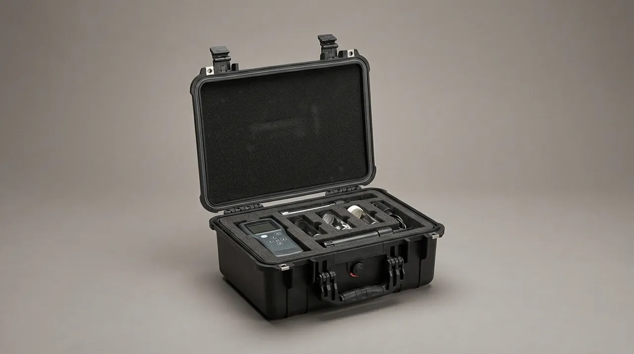
The accuracy of a modular liner depends on pocket data, not on material thickness. For custom work JUNZHIJIA asks the customer for three-dimensional data or a physical scan of the forming frame and the suction cups, and designs pocket tolerance within 1 mm of the cup lip outer diameter with at least 5 mm cavity clearance around the forming frame. Plans outside those tolerances fail far more often on long routes. Related machining practice appears in the EVA foam insert custom process article.
On-Arrival Unpacking and Acceptance Workflow
Acceptance of cartoning machine components on arrival should follow four steps in a fixed order: documents, appearance, geometry and function. Document verification comes first because it confirms whether anything is missing or mis-shipped without disturbing the packaging, which avoids later disputes.
Step one is document verification: check the packing list against part numbers, quantities and pocket numbers, and confirm that the transport test record, liner material declaration and factory parameter backup are all present. Step two is appearance inspection: check the case for serious deformation, confirm the gasket is intact and the humidity indicator card has not exceeded its limit, then look for rust, water marks and impact marks on the components. Step three is geometry inspection: examine every suction cup for a rolled lip, crack or hard spot; check pusher rod straightness by rolling it on a surface plate or using a straight edge and record the deviation; inspect the working corners and top rim of the forming frame for knocks. Step four is function inspection: work the guides back and forth by hand for smoothness, turn the cam box by hand for abnormal noise and hard spots, and run insulation and power-on self-tests on the sensing and control components.
The step most often skipped is pusher rod straightness. A simple on-site method is to lay the rod on a calibrated surface plate and measure the largest gap between rod body and plate with a feeler gauge, then compare it against the baseline recorded at dispatch; a deviation beyond 0.3 mm calls for evaluation of straightening or guide replacement. Suction cup lips should be checked at room temperature, because cold conditions raise rubber hardness and make the result look stricter than it is.
For parts with strict cleanliness requirements, unpacking belongs in the airlock, removing the outer layer before entering the cleanroom and wiping working faces in one direction with a lint-free cloth moistened with anhydrous ethanol before entry. If transport damage is suspected, complete photographic evidence before moving the part and attribute the cause against the pre-shipment self-check report. Acceptance records are best filed with the equipment file for later traceability, following the criteria in custom case acceptance AQL.
Common Questions FAQ
Q: Why must suction cups on a cartoning machine be packed individually rather than stacked on a string? A: A suction cup is moulded from rubber or polyurethane with a lip only 0.5-2 mm thick, and its sealing ability depends entirely on that lip holding a true contour while free of load. Stacking cups on a string or letting them press against each other rolls the lip and creates flat spots. Such deformation may partly recover after sitting at room temperature, but the resulting folds and hard spots cannot be removed once the cup is installed, and they directly lengthen vacuum build-up time and make pick-up unreliable. The trap is that this failure does not stop the line at once: operators typically raise vacuum pressure or extend the pick-up time to suppress the symptom, and by the time occasional carton drops appear at high cycle rates the cups are already spent and a large batch of product needs rework. Cups therefore belong in individual foam pockets machined to the lip outer diameter with tolerance within 1 mm, and they must never share a compartment with metal parts. In cold conditions rubber hardens and rebounds poorly, so winter shipments need insulation and a 24 hour settling period before unpacking.
Q: How much straightness deviation on a pusher rod requires corrective action? A: A pusher rod is a slender cantilever that may reach several hundred millimetres in length with a diameter of only ten to a few tens of millimetres, and that length-to-diameter ratio makes it highly sensitive to lateral force while relatively tolerant of axial load. As a rule of thumb, a 500 mm rod bent by 0.3 mm can already produce a visible path deviation at the end of its stroke once installed, leading to scored carton faces, uneven wear between pusher plate and guideway, and periodic vibration at high speed. A 0.3 mm deviation is therefore the threshold that triggers evaluation: at or below it the rod may stay in service with closer monitoring, above it the rod should be straightened or replaced and the guide bushing bore checked for damage from off-centre loading. A practical on-site check is to lay the rod on a calibrated surface plate and measure the largest gap between rod body and plate with a feeler gauge, comparing the result against the baseline recorded before dispatch and adding a baseline to the equipment file if none exists. Prevention starts in packaging, with supports spaced no more than 150 mm along the length, nothing laid on top of the rod and no strap tightened around its middle.
Q: What is the most overlooked failure mode in cartoning machine part transport? A: Repair records suggest the overlooked failures are not visible knocks but low-energy cumulative damage, in three familiar forms. The first is a hard spot created by a rolled suction cup lip, which is almost invisible yet steadily weakens vacuum build-up. The second is a slight bend in a long rod, unimpressive when measured statically but magnified into path error at the end of the stroke. The third is lubricant migration inside a cam box, where long-haul vibration and poor attitude concentrate grease on one side, producing noise and intermittent hesitation in the first hours of running while operators suspect the program or the cycle settings instead. All three share one signature: the damage occurs during transport and surfaces during production, leaving the responsibility boundary blurred and inviting blame in both directions. The effective response is to move inspection earlier. Record pusher rod straightness baselines, suction cup lip condition and cam box oil level marks before dispatch, then re-measure each item on arrival and write the result into the acceptance record. JUNZHIJIA recommends a component status card in the case listing the key geometric parameters and re-check method for each part, so arrival inspection has a baseline to compare against.
Q: Why must the input and output shafts of a cam box be locked during transport? A: A cam box contains conjugate cams, roller followers, output shafts and gear sets immersed in a measured grease charge, and its motion accuracy depends on stable contact between roller and cam working face. If the output shaft turns freely in transit, road vibration drives the roller through repeated small impacts against the cam face, forming tiny marks at the contact zone that alter the follower motion curve and show up as station phase drift and intermittent hesitation. Locking uses a rigid coupling clamp or a dedicated block on the exposed shaft end, with axial restraint added if needed. Three companion requirements support it: fit plastic guards over exposed shaft ends, apply protective film to flange mounting faces, and cap the oil seal lip so dust cannot lodge there and cause early leakage. A cam box shipped without grease should be sprayed with rust preventive and have every breather plugged, since moisture entering the housing forms rust on the cam faces. Keep the housing in its normal installed attitude with stacking forbidden, and during long storage turn it over by hand a few revolutions each quarter so the grease redistributes across the working faces instead of leaving dry contact patches.
Q: What hard cleanliness constraints apply to the transport packaging of cartoning machine parts? A: Cartoning machines commonly sit in the cleanroom of food or pharmaceutical secondary packaging, so their component packaging falls under cleanliness management too. Food production references GB 14881, the general hygiene regulation for food production, while pharmaceutical production is governed by GMP and may cite the ISO 14644 series for airborne particle classification. Four hard constraints follow for packaging. First, materials that shed particles, including wood wool, straw and shredded paper, are forbidden as filling because they release fibres into the cleanroom the moment a case is opened. Second, parts touching cartons or product belong in cleanroom bags and must be unpacked in the airlock. Third, liner material must be closed-cell and non-shedding, so foam debris cannot remain inside a forming frame cavity or on a suction cup lip. Fourth, liner material touching stainless steel must contain neither sulfur nor chlorine, which in damp conditions promote pitting corrosion. Handling detail matters as much: examine cups and forming frames with powder-free cleanroom gloves and never wipe them with cotton yarn, because fibres embed in elastomer surfaces and create new particle traps. These requirements match those for food packaging machinery components.
Q: What needs attention for vacuum lines and valve manifolds during transport? A: A vacuum system comprises a generator or pump, filter, solenoid valve manifold, lines and suction cups, and the most fragile elements are the spool and the bore of the lines. Spool clearances are often measured in micrometres and are highly dust-sensitive, so bag the valve manifold in an anti-static dust bag before placing it in its liner pocket, cap every port, and never let it share a case with uncleaned components. Blow each line clean before packing, fit plugs or heat-shrink caps at both ends, and coil flexible hose at a radius no smaller than fifteen times its inner diameter, because a long-term tight bend flattens the bore and reduces flow while the hose still looks intact. Where a filter is fitted, confirm the element is seated or pack it separately and note the installation direction in the packing documents so nobody fits it backwards and loses suction. Before connecting the system on site, blow the lines through with dry compressed air so residual dust does not reach the spool and jam it. If suction seems weak at arrival acceptance, check for flattened lines and cup lip condition first rather than raising the vacuum level, which would only accelerate wear on cups and pump.
Q: Why must heavy and light parts be separated by a rigid partition? A: One cartoning machine carries components spanning a wide weight range, from suction cups weighing tens of grams to base plate assemblies weighing over a hundred kilograms, and if they share a case separated only by foam, vibration gives the heavy part enough inertia to shift and press against its lighter neighbours. Foam under sustained compression takes a permanent set, and once a pocket wall collapses the light parts lose their location, travel within the case and strike the heavy part repeatedly. The remedy is a rigid barrier rather than extra foam thickness. Heavy parts sit at the bottom on an independent load-bearing structure carried directly by the case floor skids; light and precision parts go in an upper layer or their own separate pocket; and a rigid or removable divider sits between the two groups so the inertia of the heavy part cannot reach the light pocket. Heavy parts must also be pre-tensioned against their limiting faces with straps anchored at structurally rigid points and kept clear of oil seals, sensors and air ports, with the remaining voids packed using shaped foam wedges. Before the lid closes, a shake test front to back and side to side confirms that nothing collides audibly and nothing moves visibly.
Q: How can a plant that changes carton formats often reduce repeated case investment? A: Cartoning plants frequently run dozens of carton sizes, and the components that change with the format are mainly the forming frame, the suction cups and the pusher plate. Remaking an entire protective case at every changeover accumulates cost quickly, so the more economical approach is to split the case into a fixed part and a replaceable part. The case body, gaskets, latches and casters are the fixed part and are invested in once for long service; the liner module carrying the forming frame and suction cups is the replaceable part, built as a separate module per carton format so a changeover swaps the module without touching the case. JUNZHIJIA standardises the interface dimensions and fixing method between module and case so one case body accepts modules for different formats, and marks both liner and module with the carton format number and parts list reference so operators cannot install the wrong one by habit. Modular liner accuracy still depends on pocket data: every module must be designed around the actual cup lip outer diameter and forming frame cavity dimensions, because reusing an old module with modifications accumulates tolerance until cups are compressed and frames are knocked.
Q: What should packaging marks and documents contain when exporting a cartoning machine? A: Packaging marks for exported equipment should follow GB/T 191 for pictorial marking for handling of packages and GB/T 13384 for general technical conditions of mechanical and electrical product packaging, covering at least centre of gravity, lifting points, this way up prohibition, keep dry and stacking limit, ideally using internationally recognised graphic symbols with multilingual text so that unreadable marking cannot invite rough handling. On documents, a complete delivery pack normally includes a packing list stating part number, quantity, pocket number and protection measure for each item; a parts list and packing diagram marking the unpacking sequence and forbidden actions; a pre-shipment self-check report covering pusher rod straightness baselines, suction cup condition, cam box oil level marks and air path plugging records; a liner material declaration and cleanliness treatment record; a statement of the transport test standards referenced and the items actually completed; and vacuum component reset instructions. For pharmaceutical and food customers the liner declaration and cleanliness record should be suitable for filing with the equipment validation documentation.
Conclusion and Related Reading
Protecting cartoning machine components comes down to three forms of preservation: the free contour of a suction cup lip, the full-length straightness of a pusher rod, and the cleanliness of forming frame cavities and carton contact faces.
Related Reading