

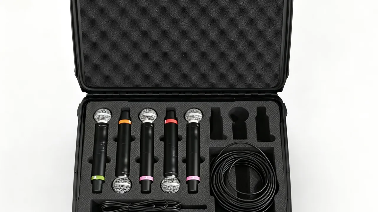
A checkweigher plays a different role on a production line from other inspection equipment. It is not looking for foreign bodies; it has to weigh every single product inside the line cycle time and reject whatever falls outside tolerance. Its headline figure is therefore not capacity but repeatability: how small the standard deviation stays when the same product passes the same point again and again. That figure rests on a very narrow chain of conditions - the mechanical and electrical state of the strain gauge load cell, the geometry and running gear of the weigh conveyor section, the repeatable action of the reject mechanism, and the integrity of the calibration chain itself. JUNZHIJIA defines a checkweigher case as a system that must return the empty zero, the span slope and the repeatability of the scale to as-shipped condition after transport. That makes restraint and isolation far more important in the packaging design than cushioning: the load cell must never be cyclically loaded, the weigh section must never be twisted by side loads, and the calibration weights must never lose a layer of metal to an impact. This article takes the five object classes - load cell assembly, weigh conveyor section, reject mechanism, electronics and transmitter, and calibration weights - and turns them into packaging and acceptance clauses that can be written straight into a purchasing technical agreement.
Checkweighers are moved and serviced more often than most inspection machines. New lines need them installed, modified lines need them relocated, worn weigh-section belts need replacing, and load cells need recalibration. The habits seen on site are predictable: the load cell goes into a turnover crate still bolted to its base, the weigh section is laid flat on a wooden pallet, weights and tools are dropped into the same plastic tote, and the reject cylinder is cut out of its piping without depressurising. None of this kills the machine on the spot. What it does is show up a few days after start-up as zero drift, growing eccentric loading error, repeatability degrading from a few milligrams to tens of milligrams, and reject actions that work intermittently. Worse, these symptoms mix with genuine site factors such as line vibration, air draughts and product temperature, which makes diagnosis extremely expensive. The value of this article is that it converts the field rule of thumb - a checkweigher hates being hit and hates being propped - into verifiable preload methods, transport stop states, packaging grades for weights, and before-and-after zero comparison criteria.
Table of Contents
- What a Checkweigher Case Must Protect Is Repeatability, Not Capacity
- Split-Case Inventory: Load Cells, Weigh Section, Reject Mechanism, Controls and Calibration Items
- Load Cells: Packaging Logic for Overload, Preload and Creep
- Weigh Conveyor Section: No Distortion, No Side Load, Protection of Mounting Faces
- Reject Mechanism: Sub-Cavity Protection for Cylinders, Arms, Pushers and Flaps
- Weigh Transmitter and Controls: Vibration, Moisture and Shielding and Grounding
- Calibration Weights and Reference Pieces: Traceability, Corrosion Protection and Impact Protection
- Insert Material and Cavities: Select by Stiffness Gradient, Not by Thickness
- Case Construction: Centre of Gravity, Lifting and Opening Frequency of Long Cases
- Transport and Stacking Validation: Writing "No Zero Drift" into the Criteria
- On-Site Reassembly, Levelling and Pre-Calibration Status Checks
- Purchasing Specification and Acceptance: Putting Parameters into the Technical Agreement
- Common Mistakes and Failure Scenario Review
- Frequently Asked Questions (FAQ)
- Conclusion and Further Reading
What a Checkweigher Case Must Protect Is Repeatability, Not Capacity
To understand how to protect a checkweigher in transit you first have to understand how its capability is defined. Industry discussion of checkweigher accuracy normally refers to international recommendation documents for automatic catchweighing instruments, in the OIML R51 family, together with national fixed electronic scale standards. On a real line, however, the working quantities are three: the verification scale interval e, the standard deviation sigma of a single pass, and the pass rate the line demands. A rule of thumb used during selection is that a resolvable tolerance has to sit within a small multiple of sigma, which means every doubling of sigma pushes the usable accuracy class of the machine down by one step.
There are three paths by which repeatability degrades.
The first is the mechanical state of the sensing element. The spring element of a strain gauge load cell is a precision machined and heat treated structure, and the gauges bonded to it form a Wheatstone bridge. Once the element suffers an impact above its ultimate overload, or is cycled into fatigue, the zero output and the sensitivity in mV/V of the bridge shift permanently. This is not a simple linear offset. It usually travels with worse hysteresis and creep, and it presents as the same product reading 500.2 g on the centre position this time and 500.6 g slightly off-centre next time.
The second path is the geometry and restraint state of the weigh section. The weigh section is normally a short belt over a roller or idler set, a weigh plate or platform, plus limit stops and anti-overload stops. The weigh plate is the mechanical extension through which force reaches the load cell. Its flatness, the uniformity of belt tension and the consistency of the limit stop clearance together decide whether product weight reaches the cell cleanly. One sideways knock that twists the plate slightly moves the load line off its design position and introduces a parasitic lateral component.
The third path is the calibration chain itself. Checkweigher accuracy is transferred from standard weights or standard pieces. The moment a weight is dented, corroded or loses its verification status, the whole traceability chain breaks. A large share of "the checkweigher is wrong" call-outs end up being a weight that is itself out of tolerance, not a machine fault.
Put the three together and the packaging objective is clear: during transport the load cell must be completely free of cyclic loading, through preload relief or locking; the weigh section must carry no lateral force at all, by shipping it separately or restraining it rigidly; and the calibration weights must not change mass in any way, through individual cells, soft support and corrosion protection. None of this is achieved by piling on cushioning material. It has to start with the case structure and the split-case plan.
Split-Case Inventory: Load Cells, Weigh Section, Reject Mechanism, Controls and Calibration Items
The correct teardown sequence for a checkweigher is: stop the line and clear product, vent air pressure, disconnect and lock out power, remove the weigh-section belt and rollers, release the connection between the weigh section and the load cell, remove the load cell assembly including base and stops, remove the reject mechanism, remove the control cabinet and weigh transmitter, then collect weights, spares and tools. Every step should be photographed and tagged, and the limit stop clearance and levelling state should be recorded, because these values are needed at reassembly.
Grouped by weight, sensitivity and cleanliness requirements, the parts fall into five classes.
| Case | Main parts | Primary risk | Baseline packaging requirement |
|---|---|---|---|
| --- | --- | --- | --- |
| Case A | Load cell, base, limit blocks, anti-overload stops | Shock overload, permanent zero shift, cable strain | One part per cavity, transport lock, low stiffness cradle, separate cable routing |
| Case B | Weigh plate, platform, rollers and idlers, weigh belt | Loss of plate flatness, side impact, bearing seat damage | Rigid plate support, flat face up, bearing seat protection, belt coiled large or laid flat |
| Case C | Reject cylinder, swing arm, pusher, flap, guide blocks, pneumatic parts | Side load on piston rod, hinge accuracy, guide damage | Cylinder retracted and locked, rod sleeve, individual location, air vented |
| Case D | Weigh transmitter, junction box, PLC modules, HMI | Vibration loosening plug-in modules, moisture, static | Vibration resistant fixing, desiccant and humidity card, shielding bag, port covers |
| Case E | Calibration weights, standard pieces, special tools | Impact changing mass, corrosion, mixing with tools | Individual cells, soft lining, no stacking, separate corrosion protection |
Case A is the one most often done badly. A load cell is not large, but it is a device that converts micron-level deflection into a weight reading, and any packaging that treats it as ordinary hardware will cause trouble. The three rules are: its own cavity, never shared; a low stiffness cradle so the body is not gripped; and a transport lock that bypasses the load path using the original stop or an equivalent support. The cable must run in its own channel, must not be used as a handle, and must not be crushed by other parts inside the case.
Case B concentrates all risk in one plane. The weigh plate and platform are finish machined for flatness. If the flat face lies down on the lining in transit, or if an upper case presses on it during stacking, flatness changes. The correct attitude is flat face up with rigid support under the back face, and nothing heavy placed on the flat face.
Case C has the most detail. The reject mechanism is a chain of kinematic pairs, and the cylinder rod, arm hinge and guide block all rely on fit accuracy to produce a repeatable action. After an impact you get faults that are extremely hard to trace, such as an occasional incomplete push or a pusher sitting a degree off. The cylinder must be retracted and locked before shipping, and the air circuit must be fully vented.
Cases D and E share one concern: mixing. Neither the transmitter nor the weights should share space with anything else. The former hates vibration and moisture; the latter hates impact and corrosion. The zoning approach used in general insert design is described in the custom foam insert design guide.
Load Cells: Packaging Logic for Overload, Preload and Creep
Load cells fail in ways that are quite different from other precision parts, which is why they deserve their own section.
Overload is the first killer. The spring element of a strain gauge cell works near its rated capacity, with a defined safe overload and ultimate overload margin above it. Those margins are usually expressed as multiples of rated capacity and differ sharply between materials, so the manufacturer data sheet is the only reliable source. Aluminium elements are markedly more brittle than alloy steel or stainless steel and have noticeably lower impact resistance. A single drop generates a dynamic load several to more than ten times the static weight, which easily exceeds ultimate overload. The result is a permanent zero shift, reduced sensitivity, or damage to one arm of the bridge that shows up as abnormal temperature drift. Note that the post-overload signature is rarely "cannot weigh at all"; it is "weighs, but repeatability is worse", which is precisely why it gets misread as a site environment problem.
Preload relief and transport locking are the main countermeasures. In service the cell carries the dead weight of the weigh section continuously, and that preload is designed in. In transport, vibration turns that preload into a cyclic load, producing fatigue and creep over time. Original designs therefore include a transport stop or locking screw that transfers the weight of the weigh section directly into the frame and bypasses the cell. If that stop is removed during teardown and lost, the cell is cycled throughout the journey. The packaging design should give the stop hardware its own labelled cavity; "just put it back in the case" is never acceptable.
Creep and hysteresis should be recorded, not felt. The slow change of output under sustained load is creep; the mismatch between loading and unloading curves is hysteresis. If both are visibly worse after transport, the element has been through stress beyond its limit. The packaging specification should therefore require the unloaded output to be recorded before packing, in mV/V or equivalent internal counts, retested immediately after reassembly on arrival, and compared, with the difference used as the criterion rather than leaving it to the fitter to judge by feel during full calibration.
Cable and sealing matter just as much. The cell cable is a four-wire or six-wire screened cable, and how the screen is terminated directly affects immunity. The cable exit is normally sealed; pulling or repeated bending can crack internal solder joints or break the seal. Packaging rules are: coil the cable at a radius of at least six to eight times its diameter, fix it in a dedicated routing channel, fit a cover on the connector, and never pull the cable out of the case to use it as a handle or sling.
| Cell type by spring element | Relative impact resistance | Packaging control focus | Mandatory post-reassembly checks |
|---|---|---|---|
| --- | --- | --- | --- |
| Aluminium alloy | Relatively low | One part per cavity, low stiffness cradle, limited drop attitude | Unloaded output, eccentric load error, repeatability |
| Alloy steel | Medium | Transport lock, base and stop hardware numbered in the same case | Unloaded output, hysteresis behaviour |
| Stainless steel, welded sealed | Relatively high | Protect the welded seal face and cable exit seal | Insulation resistance, visual check of protection rating |
| Single point, platform type | Depends on material | No side load, protect mounting holes and locating pins | Eccentric loading consistency |
| Column or spoke type | Depends on material | Protect mounting flange face and cable direction | Re-check installation torque |
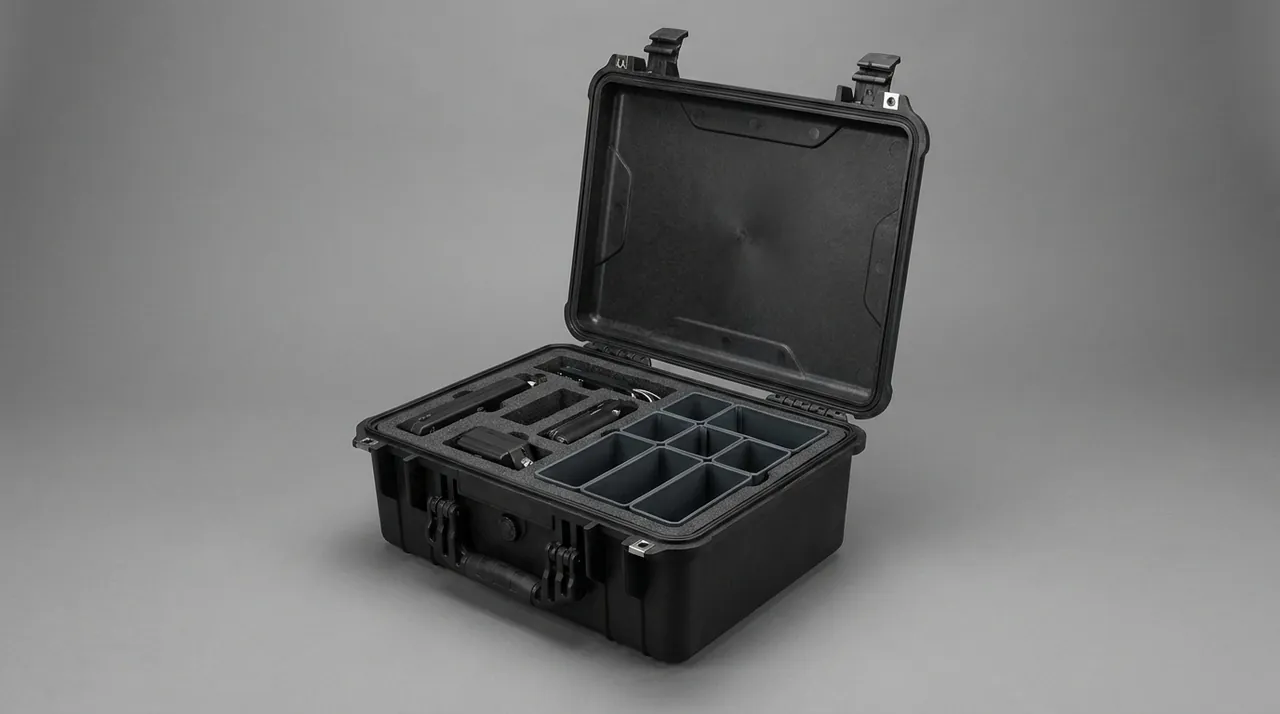
For delivery scenarios with higher shock and vibration requirements, the cushioning design can follow the energy absorption approach described for shock absorbing sealed cases, with one important caveat for this equipment: the load cell needs to be left unloaded, not squeezed tight - any clamping force applied to hold it is, in itself, a preload. The correct treatment for a load cell cavity is to support the part, never to grip it.
Weigh Conveyor Section: No Distortion, No Side Load, Protection of Mounting Faces
The weigh conveyor section is the longest element on a checkweigher and the one most easily distorted in transport. It normally consists of a short belt, front and rear rollers or idler sets, and a weigh plate or weigh platform. In service, product transfers from the upstream conveyor onto the weigh section and then onto the downstream reject section, and the clearance and height consistency at those transitions directly determine whether readings are stable.
The packaging has to protect three things.
First, the flatness of the weigh plate and platform. This is the geometric datum and the force entry face of the load cell. If the plate is bent by pressure in transit, the point at which product weight acts moves off position, which appears as increased eccentric loading error. The correct approach is: flat face up, rigid plate or wood-plastic support under the back face, and nothing heavy placed over the flat area. If stacking is unavoidable, dedicated load posts must be provided so that the load bypasses the weigh section instead of pressing on it.
Second, lateral stiffness. The weigh section is normally restrained against lateral movement by several limit blocks or anti-overload stops, and the clearance of those limit pieces is carefully set during commissioning. A lateral impact in transit - a forklift clipping the case, or adjacent cargo pressing against it in a truck - puts load onto the limit pieces that they were never meant to carry, the clearance changes, and the limit block itself may deform. The weigh section should therefore be shipped separately from the frame wherever possible; if it has to travel with the frame, rigid location all around it is required, not a foam barrier.
Third, the rollers, idlers and bearing seats. Structurally they are nothing like the load cell - they are ordinary precision machine parts - but they are equally sensitive to impact. Bearing seats should be greased and sleeved, kept in individual cells and must not rest against each other; rollers should lie on their shaft ends.
Weigh belts have one packaging characteristic that differs from general conveyor belting: they are usually very short, most often endless or short joined belts. Such a belt is neither suited to coiling into a small circle, which builds stress into the carcass, nor to folding at random. There are three workable options: keep it hung or supported on a large diameter ring; lay the whole length flat on a support board; or coil it at a large diameter in its working bend direction with end discs to hold it. The belt must be clean and dry before packing, particularly on food lines, because powder or oil residues sealed into a case become both a corrosion source and a microbial growth point. Where the belt has cleats or side walls, the root of the cleat should be isolated with a soft pad before fixing. Criteria for lengthwise stacking tests can be taken from GB/T 4857 transport packaging testing.
Reject Mechanism: Sub-Cavity Protection for Cylinders, Arms, Pushers and Flaps
The reject mechanism is the only actively moving part of a checkweigher and the hardest to repair on site once damaged in transit. The reason is that it is a series chain of kinematic pairs: air preparation, solenoid valve, cylinder, linkage or swing arm, pusher or flap, guide or bearing housing. A change in fit accuracy at any link reduces the repeatability of the reject action, and a non-repeatable reject action means out-of-tolerance product can pass through, or good product can be pushed off the line.
There are four main structural forms, each with a different packaging emphasis.
| Reject form | Critical precision parts | Transport risk | Packaging measures |
|---|---|---|---|
| --- | --- | --- | --- |
| Pusher type, linear | Cylinder rod, linear guide, pusher face | Rod bent by side load, guide block impact | Cylinder fully retracted and locked, rod sleeve, pusher face up, block located separately |
| Swing arm type | Arm hinge pin and bush, linkage | Clearance change after hinge impact, arm distortion | Hinge protector, contoured support limiting swing, never lift by the arm |
| Flap or door type | Flip shaft, bearing housing, gas spring or servo | Loss of shaft concentricity, gas spring under pressure | Support both ends of shaft, vent or remove gas spring, lock flap in closed position |
| Air blast type | High speed solenoid valve, nozzle, air manifold | Nozzle deformed or blocked, valve body vibrated | Nozzle caps, valve in individual cell, lines vented and blown dry |
Whichever form is used, three requirements are common.
The cylinder must be retracted and locked. With the rod extended it becomes a cantilever, and one lateral impact bends it. A bent rod causes incomplete stroke, uneven seal wear and sometimes seizure. The correct sequence is to end the stroke in the fully retracted position, then lock it mechanically with a lock nut, a temporary support block or a strap, so that transport vibration cannot work the rod out.
The air circuit must be vented. Residual pressure in receivers, chambers or tubing rises as temperature rises, can shift parts, and can even push an insert cavity open. Venting should be completed during teardown and noted on the case label. Filter regulators, lubricators, solenoid valves and push-in fittings should be removed and packed separately so that no load is applied to the ports.
Kinematic pairs need individual cavities with positive location, not wrapping. If pushers, guides, blocks and linkages are simply wrapped in foam and placed in one cavity, they still move around inside it during transport. The correct method is contoured location by geometry, so that every pair sits at its natural retracted position or the transport position defined by the manufacturer.
Weigh Transmitter and Controls: Vibration, Moisture and Shielding and Grounding
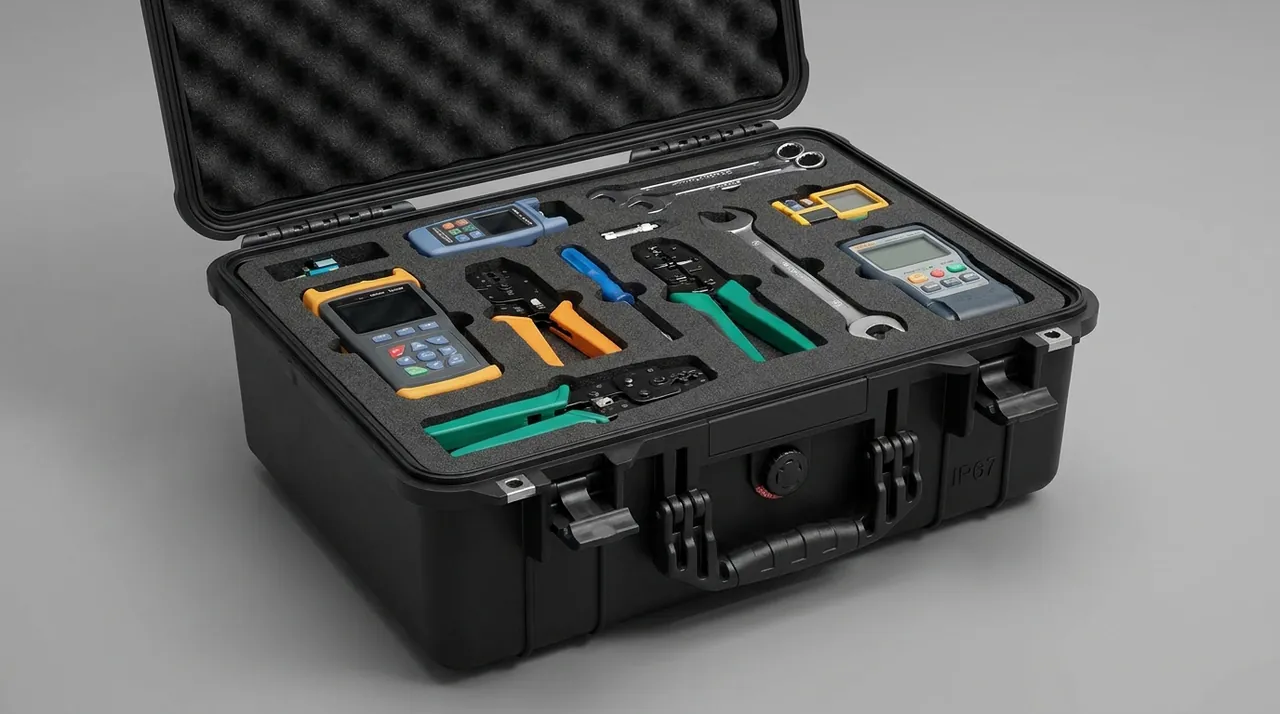
What distinguishes the electrical side of a checkweigher from that of a general machine is the analogue front end: the millivolt signal from the cell passes through amplification, filtering and a stable reference before it reaches the analogue to digital converter. That front end is sensitive to three things, all of which can be destroyed in transit.
The first is vibration. The weigh transmitter, junction box and PLC modules are normally mounted on DIN rail, held by clips or screws. Sustained low amplitude vibration in transport makes clip-mounted devices creep back and forth along the rail and puts alternating stress on wire terminals; on a fully wired cabinet, that stress eventually shows up as loose terminals. The packaging measure is to clamp devices with transport screws or temporary support blocks when the whole cabinet travels, and to bag modules in shielding bags, fix them in vibration resistant insert cells when shipped loose, and cap every bus connector.
The second is moisture. Junction boxes in the analogue front end carry a sealing rating. Aged seals or a damaged mounting face let water in, which appears as reduced insulation resistance, drifting readings or increased temperature drift. Sufficient desiccant and a humidity indicator card should go into the case to hold relative humidity in a sensible band, and any junction box removed should have its original sealing cover refitted rather than going into the case open.
The third is shielding and grounding. The screen of the cell cable, the transmitter ground and the protective earth of the frame form one complete loop. Any point crushed, pulled apart or corroded in transit turns the whole machine into one with poor immunity once it is running. Cable routing and fixing, screen integrity, and protection of the earth terminal and earth stud therefore all belong on the packing checklist.
| Electrical item | Main transport risk | Packaging measure | Confirmation after reassembly |
|---|---|---|---|
| --- | --- | --- | --- |
| Weigh transmitter | Terminal loosening from vibration, moisture ingress | Vibration resistant fixing, shielding bag, desiccant and humidity card | Terminal torque re-check, insulation check, unloaded reading comparison |
| Junction box | Seal face damage, water ingress | Refit sealing cover, individual cell, port covers | Seal appearance, insulation resistance |
| PLC and communication modules | Connector wear, static damage | Anti-static cells, connector covers | Seating check, communication self-test |
| HMI and display panel | Screen pressure, frame distortion | Rigid backer board over screen, individual cavity | Touch and display self-test |
| Power and drive modules | Heatsink loosening, terminal fatigue | Original transport screws, keep vertical | Terminal torque re-check, heatsink face check |
For deliveries across several climate zones or over long distances, the technical agreement can cite MIL-STD-810H method numbers to define the test methodology for vibration, shock and temperature and humidity, while stating clearly that citing the methodology is not a military certification, and specifying test sequence and criteria. Case sealing rating and cleaning method must also match site conditions; wet wash-down workshops should specify IP65 or above, and the selection logic is covered under IP rated protective cases.
Calibration Weights and Reference Pieces: Traceability, Corrosion Protection and Impact Protection
Calibration weights are the items most often treated as accessories in checkweigher packaging, and the ones with the most direct effect on the measurement result. They have three special properties: they are themselves the measured object, their value lies in the traceable state of their mass; their mass can change through physical damage or corrosion; and that change is usually invisible, only detectable when they go back to a metrology institute for re-verification.
Under international recommendation documents and national verification regulations, weights are divided into accuracy classes, commonly expressed as E1, E2, F1, F2, M1 and so on. The higher the class, the smaller the permitted deviation and the stricter the requirements on environment and handling. Weights are also divided structurally into one-piece solid weights and weights with an adjusting cavity, adjusted by material added inside. Cavity weights are especially impact sensitive: once the cavity cover or sealing plug deforms or loosens, the adjusting material can move or escape and the mass changes with it.
| Weight form | Structural feature | Main transport risk | Packaging requirement |
|---|---|---|---|
| --- | --- | --- | --- |
| One-piece stainless steel | No cavity, polished surface | Dents from impact, pitting in chloride environments | Individual cells, soft support, anti-corrosion film or desiccant, no stacking |
| Cavity stainless steel | Cavity with sealing plug or cover | Cover deformation or loosening, internal adjustment material shifting | As above plus cavity cover pad, no inversion or side pressure |
| Cast iron or carbon steel | Painted surface, higher mass | Coating flaking, rust, lifting impacts | Coating protection, VCI inhibitor, lifting point and sling markings |
| Small sheet weight sets | Multiple sheets stacked in a box | Sheet to sheet friction, edge burrs, mixed sets | Original dedicated box, individual sheet slots, number verification |
| Standard pieces and gauges | Geometric precision parts | Scored working faces, corrosion | Working face up, dedicated liner, individual cavity |
There are five hard packaging requirements. First, weights must sit in individual cells and must never share a cavity with tools, bolts or spares. Mixing loses in both directions: tools dent the weight, and the mass of the weight turns the tool into a hammer in transit. Second, weights must not be stacked, because in stacking the lower weight carries the upper weight amplified by dynamic shock, which easily leaves pressure marks on the surface. Third, the support surface should be soft but not sinking, generally a medium to low density closed cell foam giving full support, with a layer of flocking or non-woven on the contact face to avoid hard points. Fourth, corrosion protection must be designed for the environment, because stainless steel is not absolutely stainless; chloride cleaner residue, humid heat cycling or sea freight will still produce pitting, so vapour phase inhibitor film plus desiccant is standard practice. Fifth, traceability documents travel with the case; verification certificates, usage records and the number cross-reference table should go into a sealed document pouch, with a numbered list stuck inside the lid so that the site can check piece by piece.
The packaging thinking for metrology items has much in common with laboratory standard transport, and can draw on the graded protection practice described for metrology standard instrument cases and gauge block and precision part cases. On these cases JUNZHIJIA usually prints the correspondence between weight number, cavity number and list number directly onto the insert, so that nothing goes back into the wrong slot on site.
Insert Material and Cavities: Select by Stiffness Gradient, Not by Thickness
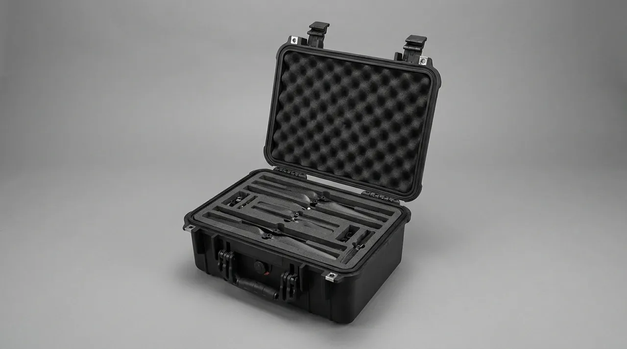
A common mistake in insert design is to assume thicker is better. For a checkweigher case, thickness matters far less than a sensible stiffness distribution, because the same piece of foam behaves in opposite ways depending on whether it sits under the weigh platform or under the load cell: the platform needs rigid support to keep its flatness, while the cell needs controlled low stiffness so that it is not gripped.
The correct approach is to build a stiffness gradient through the thickness and allocate it by part nature.
| Insert zone | Recommended material and stiffness | Function | Design points |
|---|---|---|---|
| --- | --- | --- | --- |
| Bottom load bearing layer | High density EVA or EPP, harder grade | Routes heavy part load to the case floor, resists stacking | Load path continuous, no unsupported spans or half support |
| Energy absorbing layer | XPE, medium density | Absorbs drop shock, cuts peak acceleration | Thickness calculated from mass and permitted acceleration, not guessed |
| Part contact layer | Medium density EVA, CNC routable | Limits movement in six directions, provides contoured location | Fit tolerance within plus or minus 0.5 mm, plus or minus 0.3 mm on precision faces |
| Load cell cradle | Low to medium-low density EVA with contoured recess | Supports without gripping, avoids added preload | Radiused transitions on contact faces, no sharp corners bearing on the part |
| Weight and standard support | Medium-low density closed cell plus soft face layer | Avoids hard points and friction | Individual slots, no stacking |
| Electrical part cells | Anti-static PE or EVA | Dissipates static, limits connector movement | Electronics only, never for precision machine parts |
On zoning, a checkweigher case needs number correspondence more than a general equipment case does. The reason is the number of parts removed and how similar they look - idlers, limit blocks, shims, bolt kits are easily refitted in the wrong place. A workable approach is laser marked cavity numbers on the insert, oil resistant tags on the parts, a cross-reference table inside the lid, and a packing list that records part number, cavity number and quantity. Done consistently, this noticeably reduces reassembly errors.
The trade-offs between material choices and processing methods can be checked against the density, resilience and compression set data in the protective case foam material comparison. For projects needing batch to batch consistency, hot press tooling rather than piece by piece routing may be the better route; how the tooling cost amortises is set out in custom case tooling cost analysis.
Case Construction: Centre of Gravity, Lifting and Opening Frequency of Long Cases
Checkweigher cases have one feature that clearly distinguishes them from other equipment cases: they tend to be long. The weigh section, pusher and guide are all elongated parts, so the case is stretched to take them, and a long case has three inherent structural weaknesses: low torsional stiffness, a lid that sags in the middle, and awkward one-person handling.
For torsion, the long sides need ribs or metal inserts, and the number of latches must increase with length so that no unlatched section appears in the middle. The floor is better built as an integral support plate than simply made thicker, because torsional stiffness comes more from section form than from material thickness. Middle sag in the lid directly reduces seal compression, and this is most visible in stacking, so the number of stacked layers and the load must be written into the technical agreement with a safety factor.
For handling, cases longer than about 1.2 m should have two sets of lift points or wheels, with the centre of gravity position and permitted lift points marked on the case. When slings are used, the contact position matters: single point lifting from the middle of the case is the most common error, because a long case bends visibly under that load and the internal rigid supports deform with it. Where wheels are fitted, check that their rating matches the ground conditions; the structural options are described under case wheels and trolley handles.
For opening frequency, calibration work on a checkweigher means taking weights out frequently, sometimes daily. If the lid is heavy, or has no stay or gas strut, the site will simply leave the case open and the protection is lost. The recommended approach is to give the weights their own small to medium case that one person can open easily, optionally with a gas strut and an opening stay, and to keep calibration items separate from the machine parts; the main case should use over-centre latches with metal hinges so that closing force does not decay with repeated opening. Latch, hinge and seal compatibility is covered in case latch, hinge and seal selection.
The material and process logic is similar to that for sensor cases: injection moulded cases hold tighter dimensional tolerances and allow finer internal detail, suiting load cells and electronics; rotationally moulded cases are tougher and suit long heavy parts such as the weigh section. Whether tooling is justified depends on volume and project life, and can be assessed using the OEM factory selection criteria.
Transport and Stacking Validation: Writing "No Zero Drift" into the Criteria
The core criterion for validating a checkweigher case in transport is not the appearance of the case but whether the metrological state of the load cell and weigh section has changed. Test plans should therefore include pre-packing baseline recording and post-unpacking retesting as part of the test, not just vibration and drop.
The recommended method is to record before packing the unloaded output and sensitivity of each cell, using readable parameters supplied by the manufacturer such as internal raw counts or mV/V equivalents, to record the flatness or reference dimensions at key points of the weigh plate and the limit piece clearances, then to run the test items in combination according to the delivery route, and after unpacking to retest item by item and write the differences into the acceptance criteria.
| Test category | Common methods | Focus for this equipment | Suggested criterion |
|---|---|---|---|
| --- | --- | --- | --- |
| Random vibration | GB/T 4857 series / ISTA / ASTM D4169 | Cell cable fatigue, transmitter terminal loosening, insert displacement | No displacement, wiring undamaged, unloaded output change within agreed range |
| Drop and shock | GB/T 4857 series / ISTA | Peak acceleration at cell, plate flatness | Peak within permitted window, flatness acceptable, no new pressure marks |
| Stacking and compression | GB/T 4857 series | Middle sag of long case, seal compression | No permanent deformation, sealing performance retained |
| Temperature humidity cycling | MIL-STD-810H methodology reference | Condensation, seal ageing, weight corrosion | No condensation, no rust spots on unpacking, insulation acceptable |
| Salt spray | GB/T 10125 | Idlers, bearing seats, fasteners, carbon steel weights | No red rust within the agreed duration |
| Metrological retest | Comparison against pre-packing baseline | Zero drift, eccentric load, repeatability | Drift, eccentric error and sigma all within agreed limits |
Several details in test design deserve attention. First, the sample must be a fully loaded case in its real condition, including weights and accessories; testing an empty case will not expose cell preload or insert movement. Second, drop attitudes must cover the worst direction, and for a slender case the worst is an edge drop on the long side rather than a flat drop on the base. Third, displacement marks should be made on the insert before and after vibration testing, because this is what reveals the case where the insert looks conforming but the part is actually moving inside it. Fourth, a transport shock recorder should travel inside the case to capture real shock events along the route; its value is not the report but the ability, when something later goes wrong, to answer whether the transport was over the limit or the packing was defective. Applicability of distribution cycle testing is discussed under ASTM D4169 distribution cycles.
For slender cases with an offset centre of gravity, the agreement should also fix the number of stacked layers and the storage duration, because prolonged stacking gives the insert compression set and reduces conformity on the next use. If the customer turns the case over repeatedly, planned insert replacement by cycle count is more economical than running it to failure.
On-Site Reassembly, Levelling and Pre-Calibration Status Checks
Sequence matters more than usual when reassembling a checkweigher, because the accuracy chain is long; if one link is wrong, everything downstream is compensation built on a fault.
- Unpacking check and status record. Verify piece count and numbers against the packing list, check the insert for abnormal pressure marks, condensation and rust spots, and read the shock recorder.
- Load cell visual and electrical check. Look for impact marks on the element and base, check that the cable exit seal is intact, that connector pins are level, and that the screen and earth are continuous. Retest the unloaded output and compare it against the pre-packing baseline.
- Weigh section reassembly. Refit the weigh section to the frame as recorded, check plate flatness, limit block clearance and anti-overload stop condition, then fit rollers and belt and turn it by hand to confirm it does not track off.
- Reject mechanism reassembly. Release the transport locks, restore cylinder stroke as recorded, check rod straightness and guide block clearance, reconnect air as marked and test the action at low pressure.
- Levelling and preload. Level the frame as the manufacturer requires and confirm preload is equal at every cell; skipping this step makes eccentric error look like a cell fault during calibration.
- Unloaded and eccentric load check. Watch reading stability with no load, then load at centre and at the four corners with standard pieces or known weights and confirm eccentric error is within range.
- Calibration and verification. Carry out span calibration with weights according to the verification regulation or the manufacturer procedure, then run repeatability and pass-through verification, passing the same product several times and observing the standard deviation.
- Record archiving. File the post-reassembly zero, span and repeatability data alongside the factory record as the baseline for the next cycle.
One field rule is worth memorising: if after reassembly the zero shift is small but eccentric error has clearly grown, the problem is most likely in preload and limit clearance; if the zero drifts continuously and readings follow temperature changes, the cause is more likely the cell itself or moisture in the junction box; if repeatability has worsened while eccentric loading is normal, check weigh plate flatness, belt tension and the clearance at the product transition first. Working in that order avoids mistaking a mechanical problem for an electrical one.
Purchasing Specification and Acceptance: Putting Parameters into the Technical Agreement
The point of a checkweigher case specification is not how big the case is, but turning the protection requirements into parameters.
| Specification item | What must be written | Common omission |
|---|---|---|
| --- | --- | --- |
| Part list and centre of mass | Name, outline, mass, centre of mass and permitted attitude for each part | Not stating that the weigh section must travel flat face up |
| Load cell baseline requirements | Unloaded output and sensitivity parameters to be recorded before packing, record format | No baseline required, so retest has nothing to compare against |
| Transport locking requirements | Number, condition and packing position of transport stops and locking pieces | Stop pieces packed as ordinary hardware |
| Insert stiffness allocation | Density and hardness of each layer, load path drawing, fit tolerances | Only the word foam, no stiffness gradient specified |
| Reject mechanism requirements | Cylinder retracted position, locking method, whether air is vented | Vented condition not written, case shipped under pressure |
| Weight protection | Class, number, cell arrangement, corrosion protection, whether stacking is allowed | Number correspondence and no-stacking rule not agreed |
| Case structure | Long side reinforcement, number of latches, hinge type, sealing rating | No mid-span latches or ribs on long cases |
| Testing and criteria | Test items, sequence, sample condition, metrological retest criteria | Case tests only, no metrological retest |
| Marking and documents | GB/T 191 markings, packing drawing, number cross-reference, record forms | No packing drawing or cross-reference, reassembly left to experience |
| Acceptance method | First article, sampling standard and AQL, whole case verification | No agreed treatment for non-conforming items |
Acceptance is best run in three stages. First article acceptance focuses on whether the insert stiffness allocation has actually been achieved, whether the cell cavity supports without gripping, and whether transport locking pieces are in place. In-process sampling follows the agreed sampling standard and focuses on insert dimensions and appearance. Whole case verification runs the agreed vibration and drop sequence and completes the metrological retest after unpacking. Sampling and decision rules are detailed in custom case acceptance and AQL.
The document set should include insert material reports with density, hardness and flammability rating, case material certificates, seal material reports, packing drawing and number cross-reference, whole case test report, and the metrological baseline record before and after packing. Customers with OEM or ODM requirements can agree appearance, screen printing, nameplate and serial number rules in the contract; factory assessment criteria are listed in how to choose a protective case OEM factory.
Common Mistakes and Failure Scenario Review
Mistake one: shipping the weigh section in a wooden crate or on an ordinary pallet. The moisture content and stiffness of timber are unpredictable, and fixing nails create hard points against the case. More practically, when the weigh section sits on a pallet the orientation is decided by whichever face is easiest to rest it on, and if the flat face goes down, transport becomes an attempt to hold a precision flat on an undefined support surface. The weigh section must travel flat face up with rigid support behind.
Mistake two: putting weights and tools into the same cell. This is the classic case of saving a little space and losing a traceable state. Dents or coating loss change the mass, and the change is only found at the next verification. Weights must have individual cells, soft support and no stacking, and must never share a cavity with bolts, shims or spanners.
Mistake three: gripping the load cell tightly in foam. It looks secure, but it applies a continuous restraining load to the cell. The correct attitude for a load cell is support, achieved by bearing on its underside plus position limiting, not lateral clamping.
Mistake four: removing the transport stop and not storing it separately. The transport stop or locking screw is the part that bypasses force around the cell. If it is lost, the cell carries dynamic preload throughout the journey. Give it a dedicated labelled cavity in the insert.
Mistake five: using the load cell cable as a handle. A cable carries far less pull than intuition suggests. Repeated hauling cracks internal solder joints or breaks the seal, and this type of damage often appears only as slight drift under static measurement, which is very hard to locate.
Mistake six: packing a cylinder without venting it. Shipping under pressure can shift parts and can also cause unintended motion at the moment the case is opened, which is a safety risk. Venting and confirmation of zero pressure belong in the teardown sequence.
Mistake seven: welding or grinding next to the load cell. Reassembly often needs a bracket welded on site. If welding current passes through the cell or the screened cable, it damages the gauges and internal circuitry, and grinding dust can enter the junction box and seal faces. The cell and its cable must be fully disconnected before any such work.
Mistake eight: accepting the case but not the metrological state. A case that looks right and an insert that measures right do not prove that zero and repeatability are unchanged. The real object of acceptance is the consistency of metrological parameters before and after transport.
Frequently Asked Questions (FAQ)
Q: Why can a checkweigher load cell not be clamped in foam the way other metal parts are? A: Because a clamping force is itself a load. A strain gauge cell works by converting micron-level deflection of its spring element into an electrical signal, so any force continuously acting on the element enters its load path and becomes part of the preload. Gripping it from both sides with foam looks secure but actually applies a restraining load of unknown size that varies with time and temperature, and the result is a larger zero shift plus worse hysteresis and creep. The correct method is support without gripping: the cell sits in a low stiffness cradle where its underside carries the weight, a small clearance is left all round, and low stiffness material limits large displacement only. During transport the original stop or an equivalent support bypasses the load path so that dynamic loads never pass through the element. This limits movement without introducing extra preload, and it also prevents transport vibration from turning preload into a cyclic load that causes fatigue.
Q: What actually happens if a load cell is knocked in transit, and how do you tell whether it is damaged? A: The typical consequence is not that it stops weighing but that repeatability gets worse. Once the spring element has been stressed beyond its limit, zero output and sensitivity shift permanently while hysteresis and creep deteriorate, so the same product reads differently at different positions or at different times. If one arm of the bridge is damaged, marked temperature drift can appear as well. There is a sensible order for diagnosis: measure the unloaded output first and compare it with the pre-packing baseline, then load at centre and at the four corners to see whether eccentric error has grown, then run a repeatability test by loading the same standard piece several times and looking at the standard deviation, and finally watch whether readings follow temperature changes. A small zero shift with clearly larger eccentric error points at installation preload and limit stops; continuous zero drift with temperature sensitivity points at the cell itself or moisture in the junction box. Complete this whole sequence before calibration, otherwise you compensate on a false base.
Q: Why must the reject cylinder be retracted and locked for transport, and what happens if it is not vented? A: An extended piston rod is a cantilever with far less bending resistance than a retracted one. Side impacts in transit, or other parts pressing against it when the case tilts, can bend the rod, and even a small bend causes inaccurate end-of-stroke position, uneven seal wear and sometimes seizure. On site this shows up as occasional incomplete pushes or a pusher sitting slightly off angle, faults that take a very long time to trace. In addition, residual pressure in the air circuit rises as temperature rises during the journey, which can shift the mechanism, push an insert cavity open, and even cause unintended motion at the moment of unpacking, which is a safety hazard. The correct sequence is to end the stroke in the fully retracted position, lock it mechanically with a lock nut or temporary support block, then completely vent receivers, chambers and tubing, confirm zero pressure before disconnecting fittings, and pack solenoid valves, filter regulators and push-in fittings separately so that no load is applied to the ports.
Q: Why do checkweigher calibration weights need such strict packaging, and does one knock really change the result? A: Yes, and the effect usually goes unnoticed. A weight is a measuring instrument whose value lies in its mass and in the traceable state of that mass. An impact can have several consequences: dents or coating loss change the mass directly; on a cavity weight, a deformed or loosened cover or sealing plug lets the internal adjusting material move or escape; and sheet weight sets can change their individual fit through edge burrs or friction. None of these changes is normally obvious visually, and they are only found when the weight goes back to a metrology institute, by which time every calibration result based on it has lost credibility. The packaging requirements therefore are: individual cells, never mixed with tools or bolts; no stacking, so that lower weights do not carry dynamically amplified load; a soft but non-sinking support surface to avoid hard points; corrosion protection matched to the environment, since stainless steel still pits under chloride residue and sea freight; and verification certificates plus the number cross-reference travelling with the case, with a numbered list inside the lid for on-site checking piece by piece.
Q: Why is flat face up and no pressure on top emphasised for the weigh conveyor section? A: Because the weigh plate is the face that receives product weight and the starting point of the load path into the cell. Its flatness decides whether the point of application sits where the design intends, and if the face is bent by pressure in transit the application point moves, which appears as increased eccentric loading error. Resting the flat face down on the lining, or letting an upper case press on the flat area during stacking, both produce that result. The correct method is flat face up with rigid support behind that routes load to the case floor, nothing heavy above the flat area, and if the packing must be stacked, dedicated load posts so that load bypasses the weigh section. At the same time the limit blocks and anti-overload stops between the section and the frame must be reset as recorded, because a side impact changes the limit clearance and that change degrades eccentric loading and repeatability in the same way.
Q: Why record the unloaded output before packing and retest after unpacking? A: Because without a baseline you cannot tell whether damage occurred. Early zero shift and sensitivity change are usually small, and once the line is running they are masked by product effect, ambient vibration and draughts; by the time full machine calibration reveals a problem, transport causes cannot be separated from site causes. Recording unloaded output and sensitivity before packing, using readable parameters from the manufacturer such as internal raw counts or converted mV/V values, together with reference dimensions at key points of the weigh plate and the limit clearances, and then retesting item by item after reassembly on arrival, turns the question of whether transport changed the metrological state into an acceptance question with an answer. The cost of these records is almost nil while their value for responsibility allocation and fault location is high. For customers who cycle the case repeatedly, record on every packing so that a continuous baseline chain builds up.
Q: Why is a checkweigher case harder to design when it is long and slender? A: A slender case has three structural weaknesses. First, low torsional stiffness: without ribs or metal inserts along the long side the case bends visibly when lifted and the internal rigid supports deform with it. Second, the lid sags in the middle, which leaves the seal under-compressed, and this becomes obvious after stacking, so the number of latches must increase with length and mid-span latches or reinforcement must be added. Third, one-person handling becomes impractical: past a certain length the case needs multiple lift points or wheels, with the centre of gravity and permitted lift points marked, and single point lifting from the middle must be prohibited. In addition, the worst drop attitude for a slender case is usually an edge drop on the long side rather than a flat drop on the base, and this attitude has to be included in the test plan, otherwise you get the familiar situation where the test passes but real transport still causes damage.
Q: Which tests are needed before shipment, and what should be changed first if they fail? A: Test items should be combined according to the delivery route rather than copied from a generic report. For mainly domestic road transport, the vibration, drop and stacking methods of the GB/T 4857 series apply; multimodal and export scenarios commonly use ISTA 1A, 2A or 3A, or a cycle designed under ASTM D4169; where environmental suitability has to be argued, MIL-STD-810H method numbers can be cited to define vibration, shock and temperature humidity methodology, with a note that citing methodology is not a military certification. For this equipment there are three key criteria: whether parts inside the insert have moved after vibration, whether peak acceleration at the cell during drop is inside the permitted window, and whether the middle of the long case has taken permanent sag after stacking. If a test fails, work in this order: check first that the load path is continuous, since local unsupported spans and single point loading are the most common faults; then check whether the insert stiffness allocation is right, because rigid under the platform and soft under the cell is the correct direction and reversing it is the classic error; then check that transport locking is in place; and only then consider thickening the case.
Conclusion and Further Reading
Further Reading