

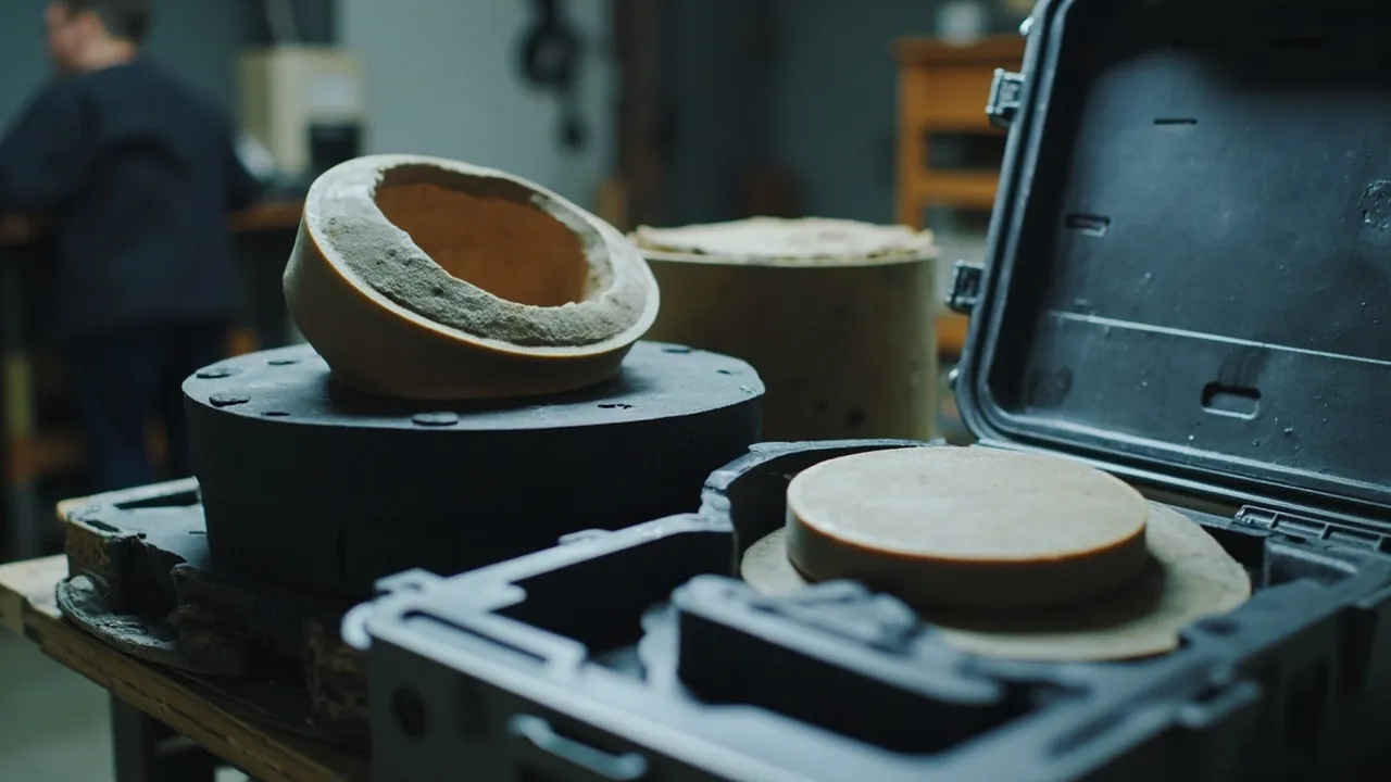
The central conflict in a rubber mold and vulcanizing equipment case is that the parts are heavy and precise at the same time. A mold body is often a solid steel block weighing tens to hundreds of kilograms, yet its most valuable features are the fractions of a millimetre of mating accuracy on the parting line, the mirror polish inside the cavity, and the few microns of flatness on the platen. These parts are not defeated by a single drop. They are defeated by three slow mechanisms: rust blooming on the parting line and cavity surfaces in a humid environment, chips knocked out of the flash groove and guide surfaces by hard objects, and gradual distortion of a platen during long-term storage and handling. The correct approach is therefore to separate protection into three independent lines: hold relative humidity below 60 percent with a vapour-phase corrosion inhibitor and desiccant to stop rust; convert point loads from heavy parts into distributed area loads with layered support and soft contact to stop impact damage; and protect flatness with orientation control to stop distortion. Each line has its own measurable criteria, and missing any one of them reappears after restart as flash, indistinct moulding detail, or inconsistent thickness.
In rubber product plants, mold losses are usually not tracked at all. A mold costing tens of thousands is often stacked in a workshop corner during a changeover season, resting on a scrap of board with the parting line face down on the floor. After the rainy season, the first run produces noticeably thicker flash, and inspection reveals a ring of rust on the parting line. The parting line then has to be reground, which changes cavity depth, puts molded detail out of tolerance, and can end in repair or scrapping. Platens follow a similar path. A platen removed from a compression molding press is often laid on a pallet for transport, develops slight bowing from its own weight and vibration, and after reinstallation shows poorer temperature uniformity and thickness consistency. This article is written for mold management, equipment maintenance, and purchasing staff in rubber product plants, and sets out the principles, metrics, workflow, and acceptance criteria for moisture, impact, and distortion protection.
Table of Contents
- 1. Why Rubber Molds and Vulcanizing Platens Fear Moisture, Impact, and Distortion
- 2. Three Critical Surface Groups: Parting Line, Cavity, and Guide and Locating Surfaces
- 3. Moisture and Rust Prevention: Vapour-Phase Inhibitor, Desiccant, and Relative Humidity Control
- 4. Vulcanizing Platens and Heating Plates: Flatness, Thermal Oil Channels, and Seal Grooves
- 5. Heavy-Duty Structure: Load Capacity, Lifting, and Castor Configuration
- 6. Inserts and Support: Should a Mold Be Stored Flat or Upright
- 7. Case Sealing Rating, Pressure Equalisation Valve, and Environmental Monitoring
- 8. Standards and Verification: IEC 60529, GB/T 4857, ISTA, and ISO 4406
- 9. Selection Process: From the Mold Register to the Technical Agreement
- 10. Common Misconceptions and Incoming Inspection Checklist
- 11. Handling, Storage, and Recommissioning Practice
- Frequently Asked Questions
- Conclusion & Related Reading
1. Why Rubber Molds and Vulcanizing Platens Fear Moisture, Impact, and Distortion
The operating conditions of rubber molds and vulcanizing equipment parts determine their precision characteristics. Rubber vulcanization typically runs between 140 and 200 degrees Celsius under closing pressures from several megapascals to well over ten megapascals, so the mold endures repeated thermal and pressure cycles. Product dimensional accuracy depends heavily on how well the parting line mates, how stable the cavity dimensions remain, and how uniform the platen temperature is.
| Component | Typical weight | Precision features | Main failure modes | Protection focus |
|---|---|---|---|---|
| --- | --- | --- | --- | --- |
| Compression molding mold | 30 to 800 kg | Parting line mating, cavity depth, molded detail depth | Parting line rust, cavity impact damage, guide pillar deformation | Moisture control, layered load bearing, soft contact |
| Injection vulcanizing mold | 50 to 1000 kg | Runner and gate geometry, cavity fit | Runner corrosion, gate impact damage | Moisture control, runner port plugging |
| Vulcanizing platen | 80 to 600 kg | Face flatness and parallelism | Slight bowing, surface scoring, channel leakage | Flatness protection, fixed orientation |
| Thermal oil system parts | Specification dependent | Channel sealing faces | Seal groove impact damage, corrosion | End-face caps, moisture control |
| Electric heating cartridges | Light per piece | Leads and insulation | Broken leads, insulation loss from moisture | Dedicated compartments, ESD control |
| Guide pillars, bushings, dowel pins | Moderate per piece | Fitting clearance | Impact damage, corrosion | Individual isolation, rust prevention |
One conclusion follows clearly from this table: a mold case is not an ordinary shipping box. It has to serve as a moisture barrier, a load-bearing pallet, and a precision protection device at the same time. These three functions reinforce each other in terms of stiffness requirements. Moisture control demands an enclosed case, and enclosure means the case must resist distortion caused by internal moisture and pressure changes. Load bearing demands a rigid base panel, and base rigidity directly affects how well the seal lip seats. Precision protection demands that the case not twist during handling or stacking. Mold case design therefore cannot start with choosing a box; it must start with the mechanical and humidity environment that box will experience.
2. Three Critical Surface Groups: Parting Line, Cavity, and Guide and Locating Surfaces
Mold protection is fundamentally surface protection. Every configuration decision can be organised around three critical surface groups.
2.1 The Parting Line: Fears Rust Most, Then Impact
The parting line is where the upper and lower mold halves mate. It is normally precision ground, and some molds are checked for contact pattern across the whole face. Its failure is progressive. Rust produces slight localised swelling, so after closing there are local gaps, and rubber is forced into those gaps under high pressure to form flash. That flash is then flattened during the next closing cycle, creating new unevenness, and the error accumulates cycle by cycle. The condition of the parting line during storage therefore directly determines product quality after restart.
Three protection points apply:
- Parting line facing up. When a mold lies flat, the parting line should face up or to the side. It must never face down onto the floor or the case base.
- Soft protective facing over the parting line. Use a clean, non-shedding soft pad or EVA facing, and make sure the material contains no plasticiser that can migrate.
- A thin rust-preventive film plus a vapour-phase inhibitor. Keep the oil film thin and even, and let the vapour-phase material cover the flash groove, threaded holes, and ejector pin holes where an oil film cannot reach.
2.2 The Cavity Surface: Carrier of Both Precision and Appearance
The cavity determines moulded detail, lettering, radii, and dimensions. Cavity surfaces are typically polished, mirrored, or chrome plated. They fail mostly through scoring and pitting. Scoring comes from contact with hard objects and careless handling. Pitting comes from electrochemical corrosion in humid conditions, particularly where water and hand sweat remain in low points.
| Cavity surface type | Surface character | Main risk | Protection measure |
|---|---|---|---|
| --- | --- | --- | --- |
| Mirror polished | Extremely low roughness | Any fine scratch transfers to the product | Full soft facing, no bare-hand contact |
| Textured | Raised and recessed detail | Sharp peaks chip, recesses hold water | Soft facing plus desiccant, never pack straight after washing |
| Chrome plated | Hard and smooth | Edge flaking; substrate corrosion beneath plating causes blistering | Avoid edge impact, keep humidity low |
| Bead blasted | Uniformly rough | Oil contamination difficult to remove | Avoid oil contact, clean on schedule |
| Nitrided | Hard and brittle | Chipping from point impact | No hard objects in the same compartment |
2.3 Guide and Locating Surfaces: Pillars, Bushings, Dowels, and Taper Blocks
Guide element failure is often overlooked because it does not directly affect appearance. But once a guide pillar or bushing wears or deforms, closing alignment degrades, load across the parting line becomes uneven, and the result still appears as flash and dimensional drift. Protection focuses on individual isolation plus rust prevention. Guide pillars and bushings should be removed and stored separately, or fitted with soft sleeves over their mating surfaces after greasing. Taper locating blocks must never be struck, because they locate through face contact, and any dent directly degrades locating accuracy.
3. Moisture and Rust Prevention: Vapour-Phase Inhibitor, Desiccant, and Relative Humidity Control
Rust is the most widespread and most preventable loss suffered by rubber molds in storage, so it deserves detailed treatment.
3.1 The Conditions for Corrosion
Once relative humidity around carbon and alloy steel exceeds a certain threshold, the surface adsorbs a liquid film thick enough for electrochemical corrosion to proceed. Industry practice generally places that critical relative humidity at around 60 percent. Holding the internal relative humidity below 60 percent, with an ideal band of 40 to 55 percent, is therefore the baseline metric for rust prevention. The word "hold" matters. Humidity repeatedly crossing the threshold is more damaging than sitting at a steady high value, because the rust layer repeatedly forms and spalls.
3.2 A Three-Layer Rust Prevention System
| Layer | Measure | Coverage | Usage point | Common error |
|---|---|---|---|---|
| --- | --- | --- | --- | --- |
| First | Surface preparation: clean, degrease, dry, apply a thin rust-preventive film | All exposed metal surfaces | Drying must be thorough; the oil film must be thin and even | Packing a wet mold; thick oil pooling |
| Second | Vapour-phase corrosion inhibitor film, paper, or powder | Dead corners, threaded holes, flash grooves, ejector holes | Volume should be well enclosed; material near but not in long-term direct contact with precision surfaces | Insufficient quantity; poorly enclosed volume |
| Third | Desiccant plus humidity indicator card | Overall internal humidity | Dose by net volume; fix in place; replace on colour change | Left loose and striking the mold; indicator never read |
3.3 Three Mold-Specific Moisture Points
- Never pack immediately after washing. Molds are often washed and still carry residual water, especially in blind features such as flash grooves, ejector pin holes, and threaded holes. Blow them dry with clean compressed air, wipe with a clean cloth where needed, allow the mold to equalise in temperature, and only then apply oil and pack.
- Treat blind holes separately. Threaded holes, ejector pin holes, water connections, and thermal oil channels are blind or semi-blind features where an oil film does not reach. Fill them with vapour-phase material or apply rust-preventive oil and cap them.
- Prevent condensation from temperature differentials. Moving a mold from an air-conditioned store into a hot, humid workshop, or unpacking directly from a cold shed onto a press, will produce condensation on cold surfaces. Allow the closed case to equalise to ambient temperature before opening. This rule matters especially for molds, because their thermal mass is large and they warm slowly.
3.4 Water Channels and Thermal Oil Channels
Internal cooling and thermal oil channels are classic hidden corrosion zones. Before storage, do four things: drain residual water by blowing the channels dry, apply rust-preventive oil or fluid inside, cap both ends, and record the action on the checklist card. If water remains in the channels, corrosion products travel with the flow into small mold cooling passages, restrict them, and cause localised cooling problems and product distortion. Where thermal oil systems are involved, fluid cleanliness targets can be referenced to ISO 4406 particle count classes, with the specific figures taken from the machine builder's documentation.
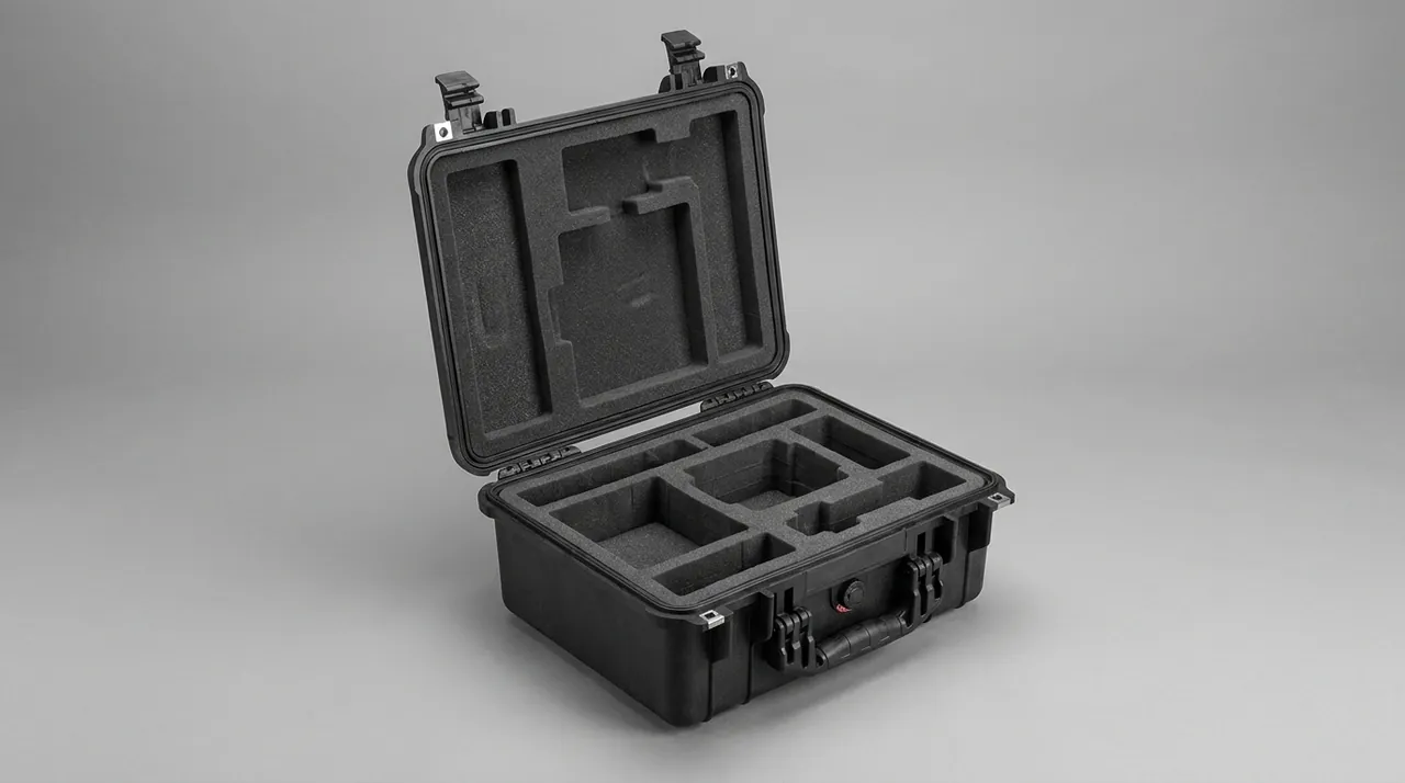
4. Vulcanizing Platens and Heating Plates: Flatness, Thermal Oil Channels, and Seal Grooves
The platen is the component that looks the most robust and behaves the most delicately.
4.1 Why Flatness Matters So Much
Compression molding works by transferring temperature and pressure from the platen into the mold simultaneously. Out-of-flatness on the platen produces two direct consequences. First, the mold is loaded unevenly, so product thickness varies, and uneven thickness means uneven cure. Second, local gaps open between platen and mold, interrupting the heat path and creating cold zones. Any handling method that induces bending must therefore be avoided during storage and transport.
4.2 Four Rules for Platen Handling and Storage
| Risky action | Consequence | Correct practice |
|---|---|---|
| --- | --- | --- |
| Two-point lifting with the middle unsupported | Self-weight bowing, flatness out of tolerance | Three or more lifting points, or a dedicated spreader beam |
| Laying flat on an uneven pallet | Localised support causes permanent distortion | Place on a flat, rigid base with evenly distributed supports |
| Face in direct contact with other metal items | Scoring and impact damage | Soft facing on the face, separate compartment |
| Standing upright leaning against a wall | Edge loading, slow distortion | Use a dedicated upright rack with full-face support |
4.3 Thermal Oil Channels and Seal Grooves
Thermally heated platens contain internal oil passages, and their connections usually have seal grooves or sealing faces. Protection follows the same logic as hydraulic components: cap or cover the connections, keep foreign objects out of the channels, and never strike a seal groove. Seal groove damage takes the form of a rolled edge or a dent. Once that happens, the seal cannot seat reliably, and oil weeps after startup. Under high-temperature operating conditions this is a safety concern, so seal grooves must be treated as a first-class protected surface that must not be struck.
4.4 Heating Cartridges and Thermocouples
The lead wires on electric heating cartridges are the weak point, and repeated bending breaks the internal resistance wire. The protection approach is to coil and restrain the leads, keep them out of load paths, and prevent them rubbing against other parts. Thermocouple compensating leads need the same protection from pulling and sharp bends. These items belong in separate small compartments, separated by soft foam and protected against static, following the approach described in the note on ESD shielding design for protective cases.
5. Heavy-Duty Structure: Load Capacity, Lifting, and Castor Configuration
Mold weight forces case design to start from load capacity rather than volume.
5.1 Three Load Design Baselines
- Design the base for two to three times the heaviest mold weight. Dynamic loads during transport can far exceed static weight, particularly in drop and vibration conditions.
- Support must be continuous and even. Mold bases are usually flat planes, and the case base should support the whole contact area rather than a few points. Localised support is the main cause of base collapse and mold distortion.
- Check contact pressure on the insert. Soft inserts compress under heavy load, and if contact pressure exceeds the material's compressive strength, the insert collapses and stops cushioning. Heavy applications need a composite arrangement with structural elements carrying the load and foam providing the soft interface, as discussed in the note on internal cushioning design for protective cases.
5.2 Lifting and Handling Structure
- Lifting points must align with the primary load path. If a lifting point sits in a thin part of the wall, the case deforms under lift and the seal suffers.
- Provide forklift pockets or a pallet base. Forklift tines pushed directly against the case base crack it, so leave clearance for the tines.
- Never sling rope around the walls. Stress concentration at the sling point is a common cause of case cracking.
- Fit castors and a telescopic handle on heavy cases, but check castor load ratings against floor conditions. The selection logic is set out in the note on case wheels and telescopic handles.
5.3 Stacking and Storage
Mold cases are typically large and heavy, which makes stacking risky. The recommendation is no stacking of loaded heavy cases, or empty-case stacking only. Where stacking is necessary, height must follow the case design load and stacking test results, heavy cases must go at the bottom, and the lower cases must be checked for distortion. Cases should not sit directly on the floor but on pallets or racking, isolating them from ground moisture.
6. Inserts and Support: Should a Mold Be Stored Flat or Upright
This is the most frequently debated question in mold case design, and the answer depends on mold geometry and where the critical surfaces sit.
| Orientation | Applicable condition | Advantage | Risk | Prerequisite |
|---|---|---|---|---|
| --- | --- | --- | --- | --- |
| Flat, parting line up | Most compression molds | Parting line protected, low centre of gravity, stable | Large footprint | Parting line up, soft facing, full base support |
| Flat, parting line down | Not recommended | None | Precision face carries load; highest risk of rust and indentation | Should be avoided |
| Upright | Low height, with a dedicated rack | Small footprint, easy access | Frame and guide surfaces loaded, tipping risk | Dedicated rack, full support, top restraint |
| On its side | Special geometries only | Accommodates unusual shapes | Locating faces may be loaded | Assess individually against mold structure |
One clear principle follows: the parting line must never be a load-bearing surface. Because the parting line is both a precision face and a sealing face, any concentrated pressure leaves an indentation that converts directly into flash on the product. Storing flat with the parting line up is therefore the default, and upright storage must place load on a side datum or the base rather than on the parting line.
Insert Material Selection
| Component | Recommended material | Reason | Note |
|---|---|---|---|
| --- | --- | --- | --- |
| Load-bearing base pad | High-density EVA or engineering plastic board with EVA facing | Combines load capacity with soft contact | No hard edges or burrs |
| Parting line facing | Clean soft EVA or expanded polyurethane sheet | Rust, impact, and shedding protection | Free of migrating plasticiser |
| Lateral restraint | EVA or polyurethane blocks | Limits lateral movement | Must not press on guide surfaces or taper blocks |
| Cavity protector | Custom molded EVA cradle | Exact fit, with finger recesses | Requires tooling; suits fixed mold sets |
| Desiccant compartment | Dedicated cavity | Keeps desiccant from striking the mold | Positioned for easy replacement |
7. Case Sealing Rating, Pressure Equalisation Valve, and Environmental Monitoring
7.1 Sealing Rating
Select the mold case sealing rating according to storage and transport conditions:
- In-plant handling and indoor storage. IP65 covers dust and water jet requirements.
- Sea freight, open or semi-open yards, humid high-rainfall regions. IP67 is recommended.
- Long-term storage beyond six months. IP67 is recommended, combined with the full three-layer rust prevention system.
Ratings are judged against IEC 60529 and GB/T 4208. One reminder matters: a second digit of 5 means water jets and 7 means temporary immersion. They cover different risks, and a jet rating does not cover condensation or immersion. Common misunderstandings are addressed in the note on waterproof cases and IP ratings.
7.2 Pressure Equalisation Valve
Mold cases that will travel by air, or between high-altitude and low-altitude sites, should be fitted with a pressure equalisation valve. It prevents the lid becoming difficult to open, the case being deformed by differential pressure, and the seal being subjected to sustained abnormal load. To be clear: a pressure equalisation valve balances pressure, not humidity. Its air flow is very small and it can never replace desiccant. The principle and configuration are set out in the note on pressure equalisation valves for protective cases.
7.3 Three Low-Cost Monitoring Devices
- Humidity indicator card. Fixed where it can be read immediately on opening, turning humidity into a number.
- Moisture or maximum-humidity recording label. Records humidity peaks during transport and storage, supporting later investigation of abnormal events.
- Shock or tilt indicator label. Used on high-value mold shipments to establish whether an over-limit impact or a tip-over occurred.
These labels cost very little, and they convert an unknowable situation into a documented one. For high-value molds they are clearly worth fitting.
8. Standards and Verification: IEC 60529, GB/T 4857, ISTA, and ISO 4406
8.1 Standards That Can Be Cited and What They Do
| Standard | Purpose | Specific application in mold cases |
|---|---|---|
| --- | --- | --- |
| IEC 60529 and GB/T 4208 | Enclosure ingress protection | Establishing IP65 and IP67 dust and water capability |
| GB/T 4857 series | Fundamental transport packaging tests | Drop, stacking, vibration, and impact methods and criteria |
| ISTA procedures | Distribution cycle simulation | Combined sequences simulating cumulative logistics damage |
| ASTM D4169 | Distribution cycle simulation | An alternative verification route common on export orders |
| MIL-STD-810H | Environmental test methods | Temperature, humidity, and vibration methods, cited as method reference only and implying no military certification |
| UL94 | Material flame retardancy classification | Case material requirements where cases sit near electrical rooms |
| ISO 4406 | Hydraulic and thermal oil cleanliness | Particle contamination targets for thermal oil and hydraulic components |
The citation of MIL-STD-810H must be strictly worded: a technical agreement should state that high-temperature, low-temperature, damp-heat, and vibration tests may reference the relevant MIL-STD-810H methods, and must not claim compliance with a military standard or imply any military certification.
8.2 Recommended Verification Items and Criteria for Mold Cases
| Verification item | Method basis | Recommended criteria |
|---|---|---|
| --- | --- | --- |
| Drop test | GB/T 4857.5 | No case cracking, latches functional, mold displacement 3 mm or less, no new scoring on critical surfaces |
| Stacking test | GB/T 4857.3 | After the design height and duration, no permanent case distortion, sealing intact |
| Vibration test | GB/T 4857.7 or ISTA | No insert collapse, no mold displacement, no abnormal wear marks |
| Dust and water ingress | IEC 60529 and GB/T 4208 | The agreed IP rating achieved, no visible water or dust inside on opening |
| Damp heat test | Referencing MIL-STD-810H | No rust on critical surfaces after testing, in combination with the rust prevention system |
| Material flame retardancy | UL94 | The agreed classification achieved, with material evidence |
9. Selection Process: From the Mold Register to the Technical Agreement
Compressed into an executable sequence, everything above becomes seven steps:
- Build a mold register. Record outline dimensions, weight, parting line orientation, critical surface locations, and any protruding guide pillars or sprue bushings for each mold set.
- Grade the critical surfaces. Parting lines, cavity surfaces, taper locating blocks, and seal grooves are first-class protected surfaces requiring dedicated facings and rust prevention.
- Map the transit route. In-plant changeovers, domestic road, sea freight, air freight, or long-term storage. This determines the IP rating and whether a pressure equalisation valve is needed.
- Calculate load capacity. Design the base for two to three times the heaviest mold weight, then define lifting points, forklift pockets, and castor configuration.
- Design the insert. Decide the storage orientation with the parting line up, then specify facing materials, lateral restraints, and the desiccant compartment location.
- Design the rust prevention system. Surface preparation sequence, rust-preventive oil specification, vapour-phase inhibitor quantity, desiccant quantity, and humidity indicator card location.
- Write it into the technical agreement. Case specification and material, insert structure drawings, verification items and criteria, how reports are supplied, sampling ratio, and acceptance method. AQL sampling logic is a sensible reference, as described in custom case acceptance and AQL.
If mold models are stable and volumes are large, custom molded cradles pay off best, and the economics are discussed in the analysis of custom case mold cost. Supplier capability is assessed in how to choose a case OEM factory. If mold models are mixed and changeovers are frequent, a modular adjustable insert combined with standardised parting line facings and rust prevention kits balances versatility against protection.
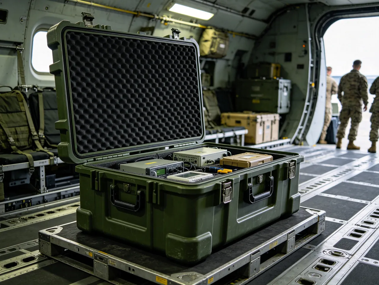
10. Common Misconceptions and Incoming Inspection Checklist
10.1 Common Misconceptions
- Misconception one: the mold is heavy, so any piece of board underneath will do. Wood absorbs moisture, distorts, supports mould growth, and cannot provide even support. It is the worst possible base for a mold.
- Misconception two: parting line down is more stable. Parting line down means the precision face carries load, maximising the risk of indentation and rust. It must face up.
- Misconception three: a washed mold can go straight into the case. Residual water in blind holes and flash grooves is the starting point of corrosion. Blow dry, equalise temperature, and oil first.
- Misconception four: more oil is safer. A thick film sags under gravity, runs off at high temperature, and traps contaminants. Thin and even is what works.
- Misconception five: any sachet of desiccant will do. Quantity must be calculated from net volume, and the sachet must be fixed in place, otherwise it strikes the mold like a small hammer.
- Misconception six: two-point lifting of a platen saves time. Two-point lifting puts a bending moment into the middle of the platen and is the main human cause of flatness failure.
- Misconception seven: using a mold case straight out of the box. Insert load capacity, facing material, gasket condition, and desiccant configuration all require inspection.
- Misconception eight: storing packed mold cases outdoors long term. Ultraviolet light and rain shorten case life significantly, and an aged gasket reduces protection sharply, as discussed in the note on protective case service life.
10.2 Incoming Inspection Checklist
- Case body. No cracks or sink marks, ribs and lifting points intact, forklift pockets usable.
- Latches and hinges. Smooth operation, no play when closed. How to judge them is described in case hinges, latches, and seals.
- Seal gasket. Continuous, no joint misalignment, no scoring, even compression mark when closed.
- Base stiffness. No visible distortion either empty or loaded.
- Insert and facing. Conforming geometry, no hard edges, non-shedding material, no plasticiser odour.
- Parting line facing. Full coverage, and handling does not scrape the parting line edge.
- Desiccant and humidity indicator card. In place, with a reading inside the acceptable band.
- Rust prevention items. Rust-preventive oil, vapour-phase material, and blind hole plugs all present.
- Documentation. Packing list, material statement, flame retardancy and ingress protection evidence, and required test reports.
- Routine maintenance. Clean after each use, service the gasket periodically, replace desiccant according to the indicator card, and reapply rust-preventive oil on schedule. Cleaning methods are described in cleaning a protective case correctly.
11. Handling, Storage, and Recommissioning Practice
11.1 The Changeover Step
Changeovers are when molds are exposed to the environment longest and face the highest risk. The recommended sequence is: remove from press, blow clean, equalise temperature, clean, apply oil, fit facing, pack, record. The temperature equalisation step is the one most often skipped. Packing a mold straight off a press at above 150 degrees Celsius traps condensation inside the case and actually accelerates corrosion.
11.2 Transport
- Move heavy mold cases with a pallet or forklift, never by hand, to avoid tip-over.
- Secure the case inside the vehicle so it cannot shift.
- Prevent other heavy loads from pressing against the case, especially at the height of the parting line.
11.3 Storage
- Keep storage area relative humidity below 60 percent, with no standing water.
- Place cases on pallets or racking, never directly on the floor.
- Do not stack loaded heavy cases. Where stacking is unavoidable, set the height from test results.
- Check the humidity indicator card and desiccant condition periodically and record the results.
11.4 Checks Before Recommissioning
- Read the humidity indicator card and moisture label to establish whether humidity was abnormal during storage.
- On opening, inspect the parting line and cavity surfaces first for rust and scoring, wiping lightly with a clean soft cloth and rust-preventive oil if needed.
- Inspect guide pillars, bushings, and taper locating blocks for impact damage.
- Inspect blind holes and flash grooves for residual material.
- Inspect the insert for collapse or loose debris and replace if needed.
- Clean per process requirements and check parting line contact before the mold goes onto the press.
- Record abnormalities and arrange repair as needed.

Frequently Asked Questions
Q: Why do rubber molds rust in storage, and why does it usually start at the parting line?
A: Because parting lines are normally precision ground, leaving a fresh surface with no mill scale, and the micro-valleys of a ground surface readily hold a water film that supports electrochemical corrosion. Industry practice generally places the critical relative humidity at around 60 percent, above which the adsorbed film is thick enough to sustain the reaction, so humidity is the decisive factor. The parting line is also the flattest and most exposed surface on the mold. If it is stored face down on the floor or against the case base, air cannot circulate near the contact area, moisture disperses more slowly, and rust appears there first. Another common trigger is packing a mold before it is fully dry after washing. Water remaining in blind holes and flash grooves evaporates and recondenses inside the sealed case, repeatedly wetting the surface. Effective prevention therefore combines dry packing, a thin oil film, a vapour-phase inhibitor, and desiccant humidity control, together with parting line up and a soft facing.
Q: What relative humidity should be maintained inside a mold case, and how is it monitored?
A: Hold internal relative humidity below 60 percent, with an ideal band of 40 to 55 percent. The word "hold" matters, because humidity repeatedly crossing the threshold is more damaging than a steady high value, since the rust layer forms and spalls repeatedly and produces deeper corrosion. Three practical monitoring methods exist. First, fix a humidity indicator card or small hygrometer inside the case where it can be read immediately on opening. Second, fit a moisture or maximum-humidity recording label to trace humidity peaks during transport and storage. Third, choose desiccant with a colour indicator and replace or regenerate it as soon as the colour changes. Desiccant quantity should be calculated from net internal volume rather than estimated by eye, and it must be fixed in its own compartment so that it cannot scatter and strike the mold in transit. A simple log of card readings and desiccant changes makes the whole cycle predictable instead of reactive.
Q: Why does a vulcanizing platen so easily lose flatness during handling and storage?
A: The main cause is inadequate support and lifting practice. A platen is heavy and stiff but not infinitely rigid. Lifted at only two points, or laid on an uneven pallet, it develops a significant bending moment at mid-length. Short term this appears as elastic deflection; over time or with repetition it becomes permanent distortion. Once slight bowing occurs, two consequences follow. The mold is loaded unevenly, producing thickness variation and uneven cure. And local gaps open between platen and mold, interrupting the heat path and creating cold zones where the product is under-cured. The correct practice is to lift at three points or more, or use a dedicated spreader beam; to store on a flat rigid base with evenly distributed supports; and if stored upright, to use a dedicated rack that supports the full face so that no edge carries load. The platen face should also be covered with a soft facing and stored in its own compartment to prevent scoring.
Q: Should a mold be stored flat or upright?
A: It depends on mold structure and where the critical surfaces are, but one rule is absolute: the parting line must never be a load-bearing surface. For most compression molds, flat storage with the parting line facing up is recommended, because the parting line is protected, the centre of gravity is low, and the mold is stable; the cost is a larger footprint. Parting line down is the orientation to avoid most, because it puts load directly on the precision face and, since air cannot circulate at the contact area, accelerates corrosion as well. Upright storage suits molds of lower height fitted with a dedicated rack. It saves floor area and is easier to handle, but the load must go through a side datum or the base, with full support and a top restraint against tipping. Whichever orientation is used, the parting line and cavity surfaces should be covered with a soft, non-shedding facing free of migrating plasticiser, and lateral restraint blocks should limit sideways movement.
Q: How should mold cooling channels and thermal oil passages be treated before storage?
A: This is the most commonly overlooked corrosion zone, because the rust is invisible from outside. Four steps are recommended. First, drain: blow residual water out of the channels with clean dry compressed air, paying attention to low points. Second, coat: introduce a suitable quantity of rust-preventive oil or fluid into the channels and tilt or rotate the mold so the film reaches every section. Third, cap: fit plugs or covers at both connections to keep foreign objects and moisture out. Fourth, record: note on the checklist card that the channels were drained and capped, so the action can be verified at recommissioning. Without this treatment, residual water remains in the channels, and the corrosion products it generates travel with the coolant into small mold passages, causing localised blockage and poor cooling that finally shows up as product distortion. For thermal oil systems, cleanliness targets can reference ISO 4406 particle count classes, with specific figures taken from the machine builder's documentation.
Q: Should a mold case use IP65 or IP67?
A: The main factor is the boundary of storage and transport. IP65 resists dust ingress and water jets from any direction, covering in-plant handling, covered workshops, and ordinary warehousing. IP67 adds temporary immersion resistance and a higher dust-tight class, suiting sea freight, open or semi-open yards, humid high-rainfall regions, and long-term storage. Rubber molds are heavy, have long repair lead times, and carry high unit value, and once rust occurs it often requires regrinding the parting line or even repairing the mold, so the loss far exceeds the price difference between cases. The judgement can therefore reasonably be conservative: whenever sea freight, outdoor handling, or storage beyond six months is involved, specify IP67. Read the definitions against IEC 60529 and GB/T 4208, and note that a second digit of 5 means water jets while 7 means temporary immersion. A jet rating does not cover condensation or immersion, and nightly condensation inside a sea freight container is precisely a common occurrence.
Q: How strong does the base of a heavy mold case need to be, and how is it verified?
A: Design the base for two to three times the heaviest mold weight, because dynamic loads in transport can far exceed static weight, especially in drop and vibration conditions. Verification can be approached three ways. First, examine the structure: does the base have a grid of ribs, do the ribs align with the lifting points, and is the support continuous. Second, run a load test: apply at least 1.5 times the design load, hold it, measure base deflection, and confirm recovery after unloading. Third, observe real use: with the heaviest mold loaded, the case should show no visible sag, the seal lip should still show an even compression mark, and the latches should still close properly. One further point deserves emphasis. Heavy applications must not rely on pure foam inserts to carry load, because foam compresses and collapses under sustained pressure and stops cushioning. The correct arrangement is a composite structure with structural elements carrying load and foam providing the soft interface.
Q: What environmental monitoring labels should a mold case carry, and are they worth it?
A: At least three types are recommended. The first is a humidity indicator card, fixed where it can be read immediately on opening, turning internal humidity into a readable number and supporting the desiccant replacement cycle. The second is a moisture recording label that shows whether humidity exceeded a threshold at any point during transport and storage, supporting investigation of abnormal events. The third is a shock or tilt indicator label, used to establish whether an over-limit impact or a tip-over occurred. This third type is particularly valuable on high-value molds, because a tip-over can cause hidden damage to a parting line or guide pillar that leaves no visible trace. These labels are inexpensive, and they convert an unknowable situation into a documented one, which also clarifies responsibility when a dispute arises. For ordinary in-plant molds a humidity indicator card alone may be enough, while sea freight or high-value molds justify all three.
Q: What preparation does a mold need for storage beyond six months?
A: Work through five steps: clean, dry, protect, control humidity, and record. Cleaning must be thorough, focusing on flash grooves, ejector pin holes, threaded holes, and water channels. Drying must confirm that no water remains in blind features, using clean dry compressed air followed by temperature equalisation. Protection uses three layers: a thin, even rust-preventive oil film, then vapour-phase inhibitor material covering dead corners, then desiccant dosed by net volume. Humidity control relies on an IP67-rated sealed case with colour-indicating desiccant, plus a humidity indicator card holding relative humidity below 60 percent and ideally between 40 and 55 percent. Recording means writing the storage date, corrosion inhibitor batch number, desiccant placement date, and inspection interval on the checklist card inside the case, and checking periodically. Avoid outdoor storage, because ultraviolet light and rain shorten the life of the case and its gasket noticeably. Where a mold is stored for more than a year, add a mid-term inspection in which the case is opened briefly, the indicator card is read, and the critical surfaces are checked under good light.
Conclusion & Related Reading
Selecting a rubber mold and vulcanizing equipment case means fitting three different defensive lines into one box. The moisture and rust line addresses relative humidity: pack clean and dry, apply a thin even oil film, cover flash grooves and blind holes with vapour-phase material, dose desiccant by net volume, place a humidity indicator card, and hold internal humidity below 60 percent with an ideal range of 40 to 55 percent, while avoiding condensation by allowing the closed case to equalise before opening. The impact line addresses critical surfaces: treat parting lines, cavity surfaces, taper locating blocks, and seal grooves as first-class protected surfaces, keep the parting line up under a non-shedding soft facing, keep bare hands and hard objects away from cavities, isolate guide elements with grease and sleeves, and never store nitrided or wear-resistant surfaces with hard items. The distortion line addresses how heavy parts carry load: the parting line must never bear load, platens must be lifted at three points or more onto flat rigid supports, the base is designed for two to three times the heaviest part weight, and lifting points align with the primary load path. Verification uses pass-or-fail criteria from IEC 60529, GB/T 4857, ISTA, and UL94, with ISO 4406 cleanliness targets added where thermal oil or hydraulic components are involved. MIL-STD-810H is cited only as an environmental test method reference and implies no military certification. JUNZHJIA, manufactured by Kexin New Materials (Guangdong) Co., Ltd., founded in 2014 in Zhongshan, Guangdong, operates an approximately 18,000 square meter factory with more than 80 production machines and over 100 employees. The protective case line covers more than 150 specifications, achieves IP67 capability, can be verified against MIL-STD-810H environmental test methods, holds ISO9001 certification, and complies with REACH and RoHS requirements. With more than 20 patents, the company provides one-stop OEM and ODM customization from product design and mold making through injection molding to inserts, liners, and logo printing, and can supply heavy-duty load-bearing and parting line protection solutions built from a customer's mold register. For volume quotations, specification requests, and customization enquiries, please use the contact page or the enquiry form on this site.
Related Reading