

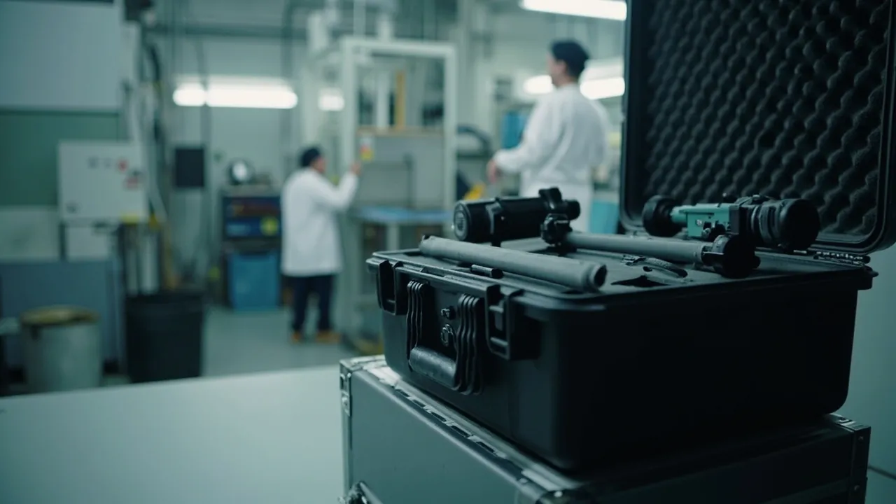
A tablet press tooling case exists to protect the most expensive and most fragile consumable in tablet manufacturing: precision punches and dies. The answer is not complicated. Tooling almost always fails in the window between removal and reinstallation, and if that window is managed so the working tip never touches hard material, never shuttles axially, never sits on residual moisture and never mixes with other specifications, abnormal tooling scrap drops dramatically.
The reality in a compression suite usually looks like this. When a product change happens, the whole tooling set comes off the machine, gets wrapped in VCI paper, dropped into a plastic bag and pushed into a steel cabinet or a cardboard box until the next changeover. Between those two moments it gets cleaned, wiped, stored, possibly sent out for regrinding, transferred between sites, and occasionally handed to a third-party carrier. That is where the damage happens: a chipped punch tip where one punch struck another, bright rub marks on the punch barrel, a scored die bore, pitting in a humid environment, and mixed specifications that can no longer be identified.
The consequences are direct. Tablet weight variation widens, tablet edges burr, ejection resistance rises, tooling life ends early, and in bad cases an entire batch is rejected. What makes it worse is that tooling damage is typically progressive, hard to see externally, and only inferable from compression results. Getting the protection right is therefore the cheapest and most immediately rewarding quality investment available in the compression suite.
This article is written for compression process engineers, tooling administrators, spare parts buyers and validation staff. It covers case construction, pocket design method, material selection, sealing class, vibration validation and acceptance traceability, with parameter tables and checklists you can lift into an internal specification. JUNZHJIA supplies custom inserts, OEM/ODM programmes and pocket sets matched to punch and die specifications for tableting tooling cases, and the practices described here come from that project experience.
Table of Contents
- 1. Why Tablet Press Tooling Needs a Dedicated Protective Case
- 2. The Tooling System: Punches, Dies, Die Rings and Die Seats
- 3. Punch Tips and Working Ends: The Most Fragile Millimetres
- 4. Die Bores and Mating Surfaces: Gauge-Level Protection
- 5. Managing Multiple Specifications and Numbering Traceability
- 6. Materials and Surface Treatment: Tool Steel, Carbide, Chrome and Nitriding
- 7. Corrosion and Moisture: Hand Moisture, Condensation and Pitting Control
- 8. Sealing Class: IP65/IP67 and Pressure Equalization Valves
- 9. Vibration and Drop: ISTA, GB/T 4857 and Tooling-Specific Validation
- 10. Cleanliness and Cleaning: Wiping and Storage Under a GMP System
- 11. Custom Inserts: How to Design Tooling Case Pockets
- 12. Acceptance and Traceability: AQL, Dimensional Reports and Batch Records
- 13. Purchasing and Maintenance: Life Management, Regrinding and Replacement
- Frequently Asked Questions
- Conclusion & Related Reading
1. Why Tablet Press Tooling Needs a Dedicated Protective Case
The difference between a tooling case and a general toolbox comes down to four points.
First, the precision class is different. The working tip chamfer, the punch barrel diameter tolerance and the overall length all directly affect tablet weight and shape. Punch-to-die clearance is typically measured in hundredths of a millimetre, so any plastic deformation from contact with a hard object changes the fit. A general toolbox is designed to hold things and be carried; precision is simply not in its specification.
Second, the failure is irreversible. Once a punch tip chips, simple regrinding does not restore it, because regrinding alters the working-end geometry and therefore tablet appearance and weight. Once a die bore is scored, the die is scrap. There is no acceptable "use it anyway" version of these failures.
Third, the cost structure is unusual. Compression tooling is bought as a set. One set may contain dozens of punches plus matching dies. The unit price of a single punch looks modest, but the total for a set is substantial, lead times are long, and losing a set to transport damage stops the line. The downtime cost far exceeds the price of the case.
Fourth, cleanliness and compliance apply. Tooling contacts drug powder directly, making it product-contact equipment. A GMP system has explicit requirements for its cleaning, storage and issue. A storage container that cannot be cleaned, carries no identification and cannot be traced to a batch does not meet the system. Where EU GMP Annex 1 sterile processes apply, cleaning and storage of product-contact parts is a specific inspection focus.
A direct test: if damage to this tooling set would stop the line, cause a batch deviation or force requalification, it needs a dedicated protective case, and that case must support management by tooling number.
A tooling case must therefore deliver four capabilities at once: precision preservation against impact and movement, environmental isolation against corrosion, moisture and dust, identifiability through numbering and traceability, and cleanability with wipeable, dead-corner-free, replaceable contact surfaces.
2. The Tooling System: Punches, Dies, Die Rings and Die Seats
Getting protection right starts with understanding what is actually in the set.
| Component | Function | Precision-sensitive feature | Main risk | Protection priority |
|---|---|---|---|---|
| --- | --- | --- | --- | --- |
| Upper punch | Applies compression from above | Working tip edge, barrel diameter, tail | Tip chipping, barrel scoring, tail deformation | Individual pocket, floating tip |
| Lower punch | Ejects the tablet from below | Working end, barrel, tail | As above; ejection end wears faster | Individual pocket, end face protection |
| Die | Forms tablet side wall and diameter | Bore diameter, bore cylindricity, end faces | Bore scoring, end face damage | Mandrel or plug protection, face isolation |
| Die ring / retaining ring | Retains the die in the die seat | Outer diameter fit, end faces | Fit surface denting | Separate storage, soft bearing |
| Die seat / tooling frame | Carries the full tooling set | Die hole position accuracy | Deformation, impact damage | Fixed as a unit, no point loading |
| Feeder / scraper blade | Feeds and levels powder | Edge straightness, base flatness | Edge rolling, base scoring | Edge protection, flat isolation |
The table shows that the punch working end and the die bore are the two surfaces where nothing can be compromised. Everything else is primarily about preventing scoring and deformation. That distinction matters because it drives resource allocation in insert design: high-precision locations get CNC-routed individual pockets with tip clearance, while general locations can be handled with laminated die-cut foam.
It also matters to distinguish single-punch and multi-punch tooling. A single-punch press uses few, larger tools. A rotary press uses many, from a few dozen to over a hundred, in smaller sizes. The packing logic differs: single-punch tooling suits large layered pockets, while multi-punch tooling suits a matrix of small pockets arranged by number and must support sequential retrieval, otherwise mixing and out-of-order return are inevitable.
3. Punch Tips and Working Ends: The Most Fragile Millimetres
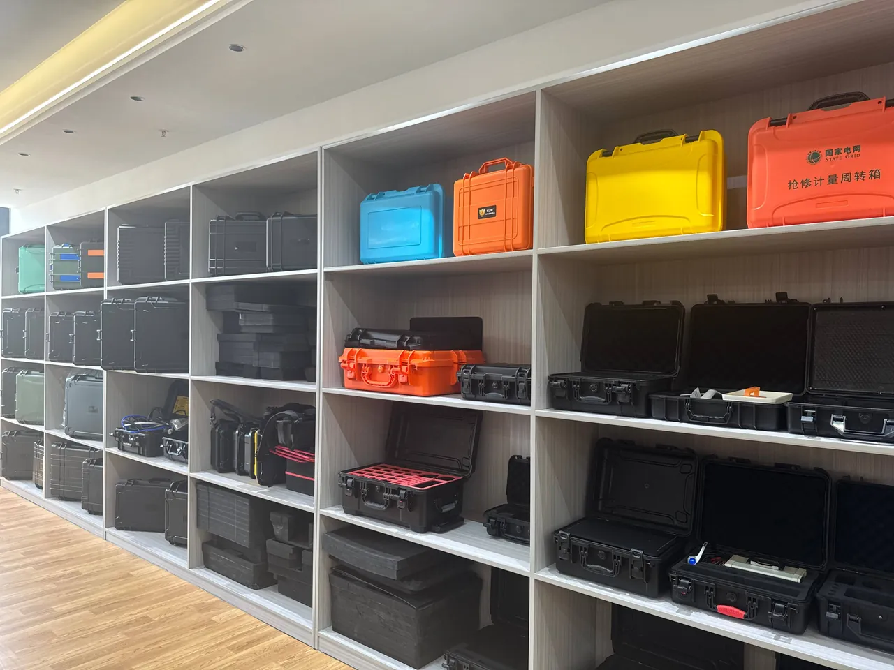
The punch working end is the most fragile part of the tool. Its geometry makes it vulnerable to exactly two things: direct impact and relative sliding.
Direct impact is far more likely at the packing bench than in transit. The usual scene is an operator grabbing punches in bunches so they strike each other, or dropping them into a container so the tip hits a hard base. A single impact is enough to chip an edge, and the damage shows up on press as edge burring or weight variation.
Relative sliding happens in transit. If a punch can shuttle axially or rock laterally inside its pocket, long-distance vibration makes the barrel rub repeatedly against the pocket wall while the tip repeatedly impacts its bearing surface. Even tiny individual energies accumulate into wear and micro-deformation.
Three core design rules follow:
- Float the working end. Leave 1.5 to 3 mm of clearance around the tip, or provide a bearing surface softer than the punch material. Never let the tip rest on a hard base plate.
- Restrain axially. The pocket must incorporate axial limitation through a step, a soft retainer strip or the lid compression layer, so the punch cannot shuttle. Limit rather than clamp; over-clamping introduces additional stress.
- Restrain radially. Provide conforming support around the mid-barrel so the punch cannot rock. Support should be a contoured contact rather than point contact.
Punch tails also need protection. The tail mates with the press ram, so its end face and retaining groove are mating surfaces. Tail deformation causes difficult installation or loosening during compression. Pocket design should therefore cover the tail too, holding the punch in a state of controlled at both ends, conforming in the middle and floating at the tip.
For visual inspection, standardise the criteria. Inspect the working end at 10x magnification: no visible chipping, no continuous scoring, no burrs. Check the barrel with a ring gauge: the go gauge passes and the no-go gauge does not. Check working-end flatness with a straight edge or dedicated gauge. Write these three checks into a tooling incoming inspection card and keep it with the case.
4. Die Bores and Mating Surfaces: Gauge-Level Protection
The die forms the tablet side wall, and its bore determines tablet diameter and side quality. The bore is a high-precision mating surface and is usually the least repairable feature in the whole set: once scored, the die is scrap.
Three dominant failure modes:
- Bore scoring. Caused by embedded hard particles or direct contact with a hard object. If dies are packed with punches, or the bore is left unprotected, scoring by a punch tip is highly likely.
- End face damage. Both die end faces are flat mating surfaces against the die-seat shoulder. Dents make the die sit tilted after installation, which affects tablet thickness consistency.
- Outer diameter denting. The die outer diameter fits the die seat; dents cause difficult assembly or loosening in use.
Three hard requirements for protection:
- The bore must carry a protective element. First choice is a dedicated mandrel or plug gauge shaped insert, second choice a soft protective sleeve. Never leave the bore exposed.
- Dies must never share a layer with punches. The case must be physically divided: a punch layer and a die layer, or a rigid divider within a shared layer. This is one of the most important lessons from real projects.
- End faces need soft bearing. Dies should lie flat on a closed-cell foam bearing surface, never contacting hard material, and when stacked in multiple layers there must be a full divider plate between layers so dies do not touch each other.
On gauge management, provide a gauge pocket next to the die pockets and store the go and no-go gauges for a given specification in the same compartment as the matching dies, to prevent cross-use. Gauges themselves need periodic verification, with the interval and records held in the asset register.
5. Managing Multiple Specifications and Numbering Traceability
A tooling case is not only a container, it is part of the tooling management system. For plants running many products on shared lines, tooling inventory is large, specifications vary and changeovers are frequent. Losses from poor management often exceed losses from transport damage.
A recommended number structure carries four fields: tooling set number (mapped to product), specification code (shape and size), punch sequence number (position within the set), and wear grade (new, in service, awaiting regrind). The number should appear both on the punch itself where laser marking exists and on the case pocket, forming a one-to-one relationship.
Three pocket numbering approaches:
| Numbering method | Process | Advantages | Limitations | Best fit |
|---|---|---|---|---|
| --- | --- | --- | --- | --- |
| Laser-engraved foam numbering | Directly engraved on the insert | Permanent, wear resistant, cannot fall off | Must be re-engraved when the insert is replaced | Long-term fixed configuration |
| Printed or hot-stamped marking layer | Marking printed on the foam surface | Low cost, batch capable | Can wear off under repeated wiping | Medium-term configuration |
| Inserted label strips | Label slot beside the pocket | Changeable at any time, supports dynamic reconfiguration | Cards can shift or be lost | Frequent multi-product changeover |
The one-case-one-sheet rule is worth adopting broadly. A packing list card stays inside the case recording tooling numbers, specifications, quantities, status, last use date, last regrind date and inspection conclusion. The card pocket should be transparent and wipeable, or use a rewritable card, so paper does not become a contamination source in a classified area.
Where regrinding is outsourced, the case should also support round-trip integrity management: use single-use numbered tamper seals, record the seal number and packing list on dispatch, verify both on return, and re-inspect against the inspection card after opening. This makes responsibility for loss and damage on the outsourced leg definable.
6. Materials and Surface Treatment: Tool Steel, Carbide, Chrome and Nitriding
Tool material and surface treatment determine corrosion and wear behaviour, and they drive liner compatibility choices.
| Material / treatment | Typical hardness | Wear resistance | Corrosion resistance | Liner compatibility notes |
|---|---|---|---|---|
| --- | --- | --- | --- | --- |
| Tool steel (Cr12MoV class) | High after hardening | Good | Moderate, needs protection | Avoid sulphur and chlorine bearing materials |
| High-speed steel | High | Very good | Moderate, needs protection | As above; chloride ions especially harmful |
| Cemented carbide (tungsten class) | Very high | Excellent | Good | Avoid embedding hard particles |
| Chrome plated | Depends on substrate | Good | Good | Avoid abrasion that breaks the plating |
| Nitrided | Depends on substrate | Good | Good | Thin layer, avoid impact |
| Stainless substrate | Medium | Medium | Good | Keep the passive layer intact |
Three practical conclusions:
- Corrosion protection is the first task. Tooling is largely tool steel and high-speed steel, whose corrosion resistance is far below stainless. Chloride ions are the main driver of pitting, so liner materials must be sulphur-free, chlorine-free and low-outgassing; regrind foam and chlorine-bearing PVC are prohibited.
- Surface layers are thin and cannot absorb impact. Once chrome or nitride layers break, the exposed substrate becomes a corrosion initiation site and the damaged area propagates. Insert contact surfaces should therefore be softer than the punch surface, protecting hardness with softness.
- Carbide fears embedded particles. Cemented carbide is extremely hard but brittle, and once a hard particle embeds in a mating surface it causes continuous wear. Liner materials must not contain hard fillers, and pockets must be free of chips and dust.
7. Corrosion and Moisture: Hand Moisture, Condensation and Pitting Control
Tooling corrosion is often underestimated because its origin is usually not water immersion but hand moisture and condensation.
Hand moisture carries salts and organic acids that form a local electrolyte microenvironment on the punch surface. If tooling is handled bare-handed after cleaning, fingerprint-shaped marks remain, and pitting can begin within hours to days. Handling after cleaning should therefore use finger cots or clean gloves, and it is good practice to apply corrosion protection or pack with a vapour-phase measure immediately after cleaning.
Condensation occurs with temperature change. The classic case is tooling stored cold and then moved directly into a warm, humid production room: the surface temperature is below dew point and water condenses on it. Three countermeasures apply. First, equalise tooling temperature with the environment before packing or opening. Second, provide a desiccant compartment inside the case. Third, use a case with a pressure equalization valve so the breathing effect of temperature change does not draw humid air inward.
Vapour-phase corrosion inhibitor materials need a compatibility warning. Conventional VCI materials release inhibitors that can conflict with pharmacopoeial requirements or cleanroom expectations. In pharmaceutical use it is safer to rely on a closed-cell, low-outgassing liner combined with a sealed case and desiccant, without chemical inhibitors. For long storage beyond a few months, a clean-grade corrosion bag plus desiccant plus sealed case gives a three-layer approach.
Humidity indication is a simple and effective management tool: place a humidity indicator card inside the case and check it before inspecting components on opening. If it is above the set threshold, inspect components before use. This costs very little and is highly effective at catching seal failures early.
8. Sealing Class: IP65/IP67 and Pressure Equalization Valves
Sealing class is determined under IEC 60529 and the equivalent Chinese standard GB/T 4208.
| Class | Dust | Water definition | Typical scenario | Notes |
|---|---|---|---|---|
| --- | --- | --- | --- | --- |
| IP54 | Limited dust protection | Splash resistant | Short in-plant transfer | Low cost; unsuitable near washdown |
| IP65 | Dust tight | Jet resistant from all directions | Most common tooling case choice | Balances sealing and handling |
| IP67 | Dust tight | Short immersion, 1 m / 30 min | Cross-zone transport, wet loading, outbound regrind trips | Pair with a pressure equalization valve |
| IP68 | Dust tight | Continuous immersion | Special requirements | High cost, rarely necessary |
Why a pressure equalization valve matters for tooling cases. Tooling cases are small but need meaningful sealing, and they routinely experience temperature swings between production floor, warehouse and outbound regrinding. A fully sealed case develops an internal-to-external differential: rising temperature bows the lid and loads the latches, while falling temperature creates vacuum so the lid is hard to open and the gasket is sucked out of shape. A pressure equalization valve uses a hydrophobic and oleophobic microporous membrane to breathe slowly while preserving IP65 or IP67. The principle and selection logic are covered in how the case pressure equalization valve works and how to select it. One specific warning: after a round trip for regrinding, let the case reach room temperature before opening, so a cold case does not condense moisture the moment it is opened in a humid production room.
Additional measures against condensation ingress:
- Avoid placing hygroscopic paper materials inside; use rewritable or laminated cards instead.
- If the liner is found damp on opening, remove components, inspect them, and dry the liner before returning it to service.
- Replace any gasket showing permanent set immediately, otherwise moisture migrates along the deformed section.
Seal material and replaceability matter for the same reason. The gasket is a wear item and replaceability determines whether the case lives for years. Material differences are compared in protective case seal materials compared, and seal and hinge structure is explained in toolbox hinge, latch and seal structure explained. Where fire performance is specified, request a UL94 rating certificate.
9. Vibration and Drop: ISTA, GB/T 4857 and Tooling-Specific Validation
Tooling validation differs from general equipment case validation in two ways. First, the pass criterion is not whether the case survived but whether punch tips and die bores are still acceptable. Second, judgement depends on gauges rather than visual inspection.
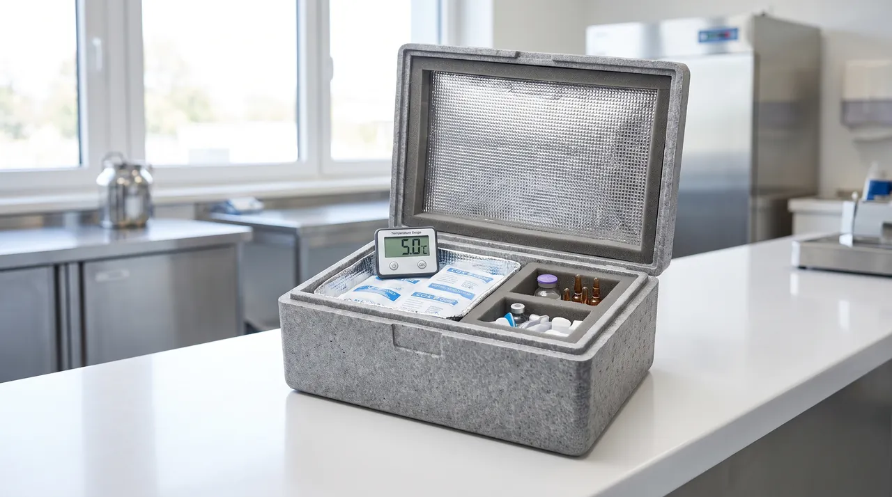
Three standards provide the basis:
- ISTA series. ISTA 1 for basic integrity, with ISTA 2 and 3 closer to real distribution. See ISTA transport testing procedure and case validation.
- GB/T 4857 series. Chinese basic test methods for transport packages covering vibration, impact, stacking and drop. See GB/T 4857 transport packaging testing for cases.
- MIL-STD-810H. Environmental test methods, of which Method 514 (vibration), 516 (shock), 507 (humidity) and 509 (salt fog) are commonly cited. Note that citing this standard is a reference to environmental test methodology and does not mean the product holds a military certification. See MIL-STD-810H environmental testing and case compliance explained.
Recommended tooling-specific validation criteria:
| Test item | Condition (typical) | Pass criterion | Inspection tool |
|---|---|---|---|
| --- | --- | --- | --- |
| Corner drop | Per ISTA drop sequence, including corner, edge and face | No visible tip chipping at 10x magnification | Magnifier or stereo microscope |
| Random vibration | Per ISTA or GB/T 4857 vibration profile | Barrel go gauge passes, no-go gauge does not | Plug or ring gauge |
| Stacking | Loaded to transport stacking height | No permanent case deformation, no insert collapse | Visual plus dimensional measurement |
| Die bore inspection | Every die after test | Go gauge passes, bore free of scoring | Bore plug gauge |
| Humidity cycling | High temperature and humidity cycles | No pitting, no rust spots | Visual and surface inspection |
| Post-test cleanliness | Open case after test | Liner shedding within acceptance limit | Clean cloth wipe plus particle count |
Three actionable design principles:
- Locate before you cushion. Stop the punch moving inside its pocket first, then absorb energy. A punch loose in thick foam wears its tip through repeated displacement.
- Separate by layer. Punches in one layer, dies in another, with a rigid divider plate between. The divider prevents upper-layer components from being pressed down into lower pockets during vibration.
- Design the lid compression layer. The inside of the lid should carry a full compression layer, usually soft foam or a foam-and-board composite, that applies uniform pressure over the insert when closed to stop components bouncing. The layer must not be too thick, or the lid becomes hard to close and the latches are overloaded.
Also watch the hydraulic and lubricated components of the press. After impact in transit, wear debris inside the hydraulic overload protection system, gearboxes and lubrication pumps contaminates the lubricant, and hydraulic oil cleanliness is commonly controlled against ISO 4406 contamination codes. Where the customer specifies oil cleanliness, the robust approach is to drain before transport and plug the ports, then refill to procedure after delivery. Where oil must travel with the unit, fix the attitude to prevent inversion, avoid severe shock, and check oil level and oil sample before handover.
10. Cleanliness and Cleaning: Wiping and Storage Under a GMP System
Tooling is product-contact equipment, so its cleaning and storage must be managed inside the GMP system.
Cleaning points:
- Select cleaning agents compatible with the tooling material and surface treatment, and avoid chlorine-bearing agents, which cause pitting.
- Dry thoroughly after cleaning; residual moisture is the direct driver of pitting.
- Pack immediately after cleaning rather than leaving tooling exposed in the production environment.
- Handle with finger cots or clean gloves; never touch working ends or bores bare-handed.
Storage requirements:
- Store in a dry, dark environment with stable temperature, away from humid areas such as cleaning rooms.
- Keep the case closed but do not over-compress the latches, to avoid long-term gasket compression set.
- Store in dedicated zones by number; do not mix products or specifications.
- Check humidity indicator cards and component condition periodically and keep inspection records.
General case cleaning methods and agent selection are covered in how to clean a protective case correctly; only the agent choice has to meet cleanroom requirements.
Where classified areas are involved, a tooling case entering a cleanroom should be configured against the ISO 14644 classification framework and the material transfer requirements of GB 50457: fully wipeable external surfaces, a cavity free of blind holes and liquid traps, and where necessary a pressure equalization valve to avoid turbulence on opening. Where the case material also needs low migration and low odour, for example in food or nutraceutical tableting, the GB 4806 series on food-contact materials is a useful reference for material safety assessment.
11. Custom Inserts: How to Design Tooling Case Pockets
The custom insert is the core value of a tooling case. The design process standardises into six steps.
Step one: inventory and classification. List every punch and die with specification code, quantity, dimensions (working-end diameter, barrel diameter, overall length), weight and number. Group as punches, dies, die rings and other.
Step two: layer count and layout. The principle is one layer for punches, one for dies, one for accessories. Where punch counts are high, a two-layer punch layout is possible but requires a rigid divider between layers. Leave 10 to 15 percent of height for cushioning and lid compression layers.
Step three: pocket geometry.
- Punch pockets: bore sized to barrel diameter plus 0.3 to 0.8 mm clearance depending on vibration requirements; depth covering at least 70 percent of the punch body; a 1.5 to 3 mm floating clearance or soft bearing surface at the base to protect the working end; a step or soft retainer at the mouth for axial restraint.
- Die pockets: bore sized to outer diameter plus 0.2 to 0.5 mm; depth covering at least 60 percent of die height; an adjacent pocket for the bore protection plug; soft bearing at the end face.
- Matrix arrangement: multi-punch tooling arranged in number order so rows and columns serve the numbering system and sequential retrieval and counting are practical.
Step four: forming method.
| Forming method | Process | Advantages | Limitations | Best fit |
|---|---|---|---|---|
| --- | --- | --- | --- | --- |
| CNC routing | CNC milling from solid foam | High precision, precision pockets and tip clearance | Lower material utilisation | Precision punch pockets, irregular tooling |
| Die cutting | Blade die cutting plus lamination | Low cost, fast lead time, easily replicated | Limited complex 3D cavities | Regular punches, higher volumes |
| Moulded foaming | In-mould foam bonding | Best conformity, low unit cost at volume | Requires tooling; costly to change | High-volume standard tooling sets |
Process comparisons are in EVA foam insert custom process explained and the custom foam insert design guide. For critical features such as the punch working end, CNC routing is normally used to guarantee tip clearance accuracy, while the barrel section, which is high in count and uniform in specification, can use laminated die cutting to control cost.
Step five: marking and traceability. Laser-engrave numbers beside pockets or provide label slots, add a packing list card pocket, and fit an external label area and tamper seal holes.
Step six: prototype and validation. Fit a 1:1 foam prototype first to confirm handling force and clearance, then run drop and vibration validation in the loaded condition and inspect with gauges and magnification after opening. In custom insert work JUNZHJIA builds from tooling drawings or physical samples and can produce loaded validation sample cases alongside the design.

12. Acceptance and Traceability: AQL, Dimensional Reports and Batch Records
Three acceptance levels for a tooling case:
- Appearance and structure. No deformation or flash; smooth hinge operation; continuous unbroken gasket; pockets matching drawing; measured tip clearance within design value.
- Dimensions and fit. Critical dimensions sampled against drawing; sample fitting to confirm handling force; uniform lid-to-body gap when closed; lid compression layer compression within design.
- Performance. IP class verification, drop and vibration sampling and seal tightness checks by pressure decay or immersion, as agreed.
AQL sampling follows GB/T 2828.1 or ISO 2859-1 for inspection level and acceptance quality limit; the method is described in custom case acceptance and AQL sampling.
Documents to request:
| Document class | Content | Purpose |
|---|---|---|
| --- | --- | --- |
| Material certificates | Body and liner material reports, RoHS and REACH where required by export market | Cleanliness and compliance review |
| Performance reports | IP class test reports under IEC 60529 / GB/T 4208 | Evidence of sealing capability |
| Transport validation | ISTA or GB/T 4857 test reports in the loaded condition | Evidence of protective capability |
| Flammability | UL94 rating where fire requirements apply | Safety review |
| Dimensional records | Inspection records for critical dimensions and tip clearance | Basis for incoming inspection |
| Batch traceability | Case batch number, insert revision, gasket lot | Quality traceability |
Recommended batch record contents: case batch number, insert revision number with pocket layout revision, gasket lot, date of manufacture, insert pocket list, tamper seal number. A tooling case record can be tied to the tooling ledger to give case-to-pocket-to-tooling-number-to-use-record-to-regrind-record traceability in multiple directions.
13. Purchasing and Maintenance: Life Management, Regrinding and Replacement
Make or buy? Tooling case inserts are highly customised; making them in house requires foam conversion equipment and design capability and is rarely economical. The sensible route is standardised case body plus customised insert, which controls cost while preserving precision. Tooling cost calculation is in custom case mould cost analysis; for plants with many specifications and modest volumes, a combination of laminated die cutting and CNC routing is usually more economical than tooling.
OEM/ODM cooperation suits tablet press and pharmaceutical equipment manufacturers. A builder can deliver the tooling case as a standard accessory to the end-user plant, branded to the builder and configured internally to the shipped tooling specifications. JUNZHJIA supports this model, including model-specific insert layouts, pocket sets matched to the tooling list, and structural reinforcement and packaging for export. Supplier evaluation criteria are in how to choose a protective case OEM factory.
Life management and maintenance:
- Inspect gaskets periodically, every 6 to 12 months, replacing immediately on hardening, cracking or permanent set.
- Assess inserts on a cycle. Replace when pockets deform, tip clearance closes up, or surface shedding exceeds limits. Tip clearance is the critical indicator and should be measured annually. See protective case service life and influencing factors.
- Avoid direct sun and heavy loads. Both UV and prolonged compression shorten service life.
- Manage regrind round trips with tamper seals and packing lists, and re-inspect against the inspection card on return to confirm no missing items and no new damage.
- Scrap criteria. Replace the insert when it shows through-damage, out-of-tolerance pockets or obvious embrittlement, rather than attempting repair.
Frequently Asked Questions
Q: What goes wrong most often with tablet punches in transit, and why?
A: The most common failures are chipped working-end edges and scored punch barrels, followed by die bore scoring and surface pitting. Chipping usually happens at the packing bench rather than in transit, because operators habitually grab punches in bunches so punches strike each other, or drop them into a container so the tip hits a hard base. A single impact is enough to leave a visible chip. Barrel scoring comes mainly from relative movement in transit: if a punch can shuttle axially or rock laterally inside its pocket, long-distance vibration makes the barrel rub repeatedly against the pocket wall while the tip repeatedly impacts its bearing surface. Die bore scoring usually results from packing dies with punches while the bore has no protective plug, so a punch tip scores it directly. Surface pitting comes from hand moisture and condensation, since tool steel and high-speed steel corrode far more readily than stainless, and a fingerprint left by bare-handed handling can create a pitting initiation site within hours to days. What all four share is that the damage is irreversible and cannot be recovered by simple regrinding.
Q: How much tip clearance should a punch pocket actually have?
A: Tip clearance is designed so the working end neither contacts hard material nor loses restraint through excessive space, so the value depends on punch specification and transport conditions. The general starting range is 1.5 to 3 mm around the working end. For punches with a small working-end diameter and high precision requirements, use the lower end, around 1.5 to 2 mm, so lateral rocking is limited and the tip cannot reach the pocket wall. For punches with a larger working-end diameter and greater mass, use the upper end, around 2.5 to 3 mm, because a heavier punch carries more impact energy if it does contact the wall and needs more clearance to avoid contact altogether. Where clearance cannot be provided, the alternative is a bearing surface softer than the punch material so the working end rests on soft material; in that case compression should stay within one to two times the punch weight so no permanent indentation forms. Whichever approach is chosen, put the measurement method on the drawing and verify it at incoming inspection with feeler or depth gauges as an acceptance item.
Q: Why must dies be stored separately from punches?
A: The core reason is that the die bore and the punch working end are two very different precision surfaces, and packing them together causes mutual damage. The die bore is a high-precision mating hole with a tight diameter tolerance; once scored or galled it cannot be repaired and the die is scrap. The punch working end is a hard, sharp edge, and in a vibrating environment any contact between the two acts like a cutting tool on the bore. Conversely the die outer diameter is usually a ground surface whose edges can also damage a punch tip, so the damage runs both ways. The right approach is a physical division in the case structure: one layer for punches, one for dies, with a rigid divider plate between them, since the divider prevents upper components being pressed into lower pockets under vibration. In addition, the die bore must carry a dedicated mandrel or plug-gauge shaped protector, and the end faces must bear on soft material rather than contacting anything hard. If case size prevents separate layers, at minimum use a rigid divider within the shared layer, with the divider taller than half the component height.
Q: Does a tooling case need IP67, and does a pressure equalization valve affect sealing?
A: IP65 is sufficient in most scenarios, and IP67 addresses specific transport routes. IP65 means dust tight and protected against water jets from any direction under IEC 60529 and GB/T 4208, which fully covers in-plant transfer, covered loading and the warehouse-to-production-floor route, at lower cost and with easier handling. IP67, meaning short-term immersion, becomes relevant for cross-zone transport with wet or uncovered loading, transfer routes through washdown areas, outbound and return trips for regrinding, and export sea freight exposed to spray or container seepage. Choosing IP67 normally requires a pressure equalization valve, because otherwise temperature-driven differentials make the lid hard to open and deform the gasket. The valve does not compromise sealing: its core is a hydrophobic and oleophobic microporous membrane that lets air molecules pass slowly to equalise pressure while liquid water and solid particles cannot penetrate the pores, so a case with a correctly installed valve still meets IP65 or even IP67. One specific reminder: after a round trip for regrinding, let the case reach room temperature before opening so a cold case does not condense moisture as soon as it is opened in a humid production room.
Q: How should a tooling case be protected against corrosion, and can vapour-phase inhibitor paper be used?
A: The key is keeping water and electrolyte out, and vapour-phase inhibitor paper should be used cautiously in pharmaceutical settings. Tooling is largely tool steel and high-speed steel with weak corrosion resistance, and chloride ions are the main driver of pitting, so the first line of defence is a liner that is sulphur-free, chlorine-free and low-outgassing; regrind foam and chlorine-bearing materials are prohibited. The second line is controlling hand moisture: handling after cleaning must use finger cots or clean gloves, because fingerprints left bare-handed contain salts and organic acids and create pitting initiation sites within hours to days. The third line is controlling condensation: equalise tooling temperature with the environment before packing, provide a desiccant compartment in the case, and use a pressure equalization valve so breathing does not draw humid air inward. On vapour-phase inhibitor materials, the inhibitors released by conventional VCI paper can conflict with pharmacopoeial requirements, cleanroom expectations and product-contact compatibility, so pharmaceutical use should minimise or avoid them and rely instead on a closed-cell low-outgassing liner plus sealed case plus desiccant. For storage beyond a few months, add a clean-grade corrosion bag for three-layer protection. A humidity indicator card inside the case is also recommended.
Q: Is it better to use one shared case for multiple tooling specifications, or one case per specification?
A: It depends on changeover frequency and how much specifications differ, and both have valid use cases. One case per tooling set gives clear management, zero risk of mixing and no sorting on retrieval, but requires more cases, more storage space and higher cost, which suits plants with infrequent changeovers, few tooling sets and large specification differences. Sharing a case is efficient in space and cost but depends on strict numbering and reconciliation, otherwise mixing and missing items appear, which suits specifications that are similar and can be arranged in a uniform matrix. The most common compromise in real projects is a modular insert: one case body, with an insert built as a frame layer plus replaceable pocket blocks, so switching to another tooling set only requires swapping pocket blocks while the frame layer is reused. This controls both case count and cost while eliminating cross-specification mixing. Another workable compromise is layer adaptation, using different layer plate thicknesses in the same body for tooling of different heights. Whichever approach is chosen, a packing list card should stay inside the case recording tooling numbers, specifications, quantities and status, with card reconciliation built into daily management.
Q: How should outbound and return trips for tooling regrinding be managed?
A: Round-trip management focuses on verifiable integrity and definable responsibility, and four measures are recommended. First, use single-use numbered tamper seals: record the seal number, packing list and each tooling number and condition at dispatch, then verify the seal number and its appearance on return to confirm the case was not opened or substituted. Second, one case one list: the packing list card travels with the case recording tooling numbers, specifications, quantities, dispatch date, regrind requirements, return date and inspection conclusion, and the card pocket should be transparent and wipeable so paper does not become a contamination source. Third, inspect every tool on return against the inspection card: check the working end at magnification for new chipping or scoring, check punch barrel diameter and die bores with gauges where the go gauge passes and the no-go gauge does not, and record the conclusion. Fourth, on transport conditions, use an IP67 case with a pressure equalization valve for the round trip and let the case reach room temperature after return before opening, so a cold case does not condense moisture when opened in a humid production room. Together these measures make responsibility for loss and damage on the outsourced leg definable and also feed supplier performance evaluation.
Q: How can you tell whether a tooling case supplier really understands compression tooling?
A: Five technical questions will reveal it. First, tip clearance: can they state the practical clearance range around the working end and explain how it changes with punch specification? Second, layer logic: do they proactively require separate layers for punches and dies with a rigid divider, and explain why die bores need protection plugs? Third, validation criteria: can they describe inspecting tips at magnification and checking punch barrels and die bores with gauges after testing, rather than just saying the case passed a drop test? Fourth, material compatibility: can they explain why the liner must be sulphur-free, chlorine-free and low-outgassing, and why vapour-phase inhibitor materials are used cautiously in pharmaceutical settings? Fifth, traceability design: do they proactively propose laser-engraved pocket numbering, packing list card pockets, tamper seal holes and a one-case-one-sheet rule? If the discussion only covers size, colour and price, the experience is probably limited to general industrial boxes. In this type of project JUNZHJIA normally starts with tooling inventory and classification, then issues a pocket layout proposal and validation plan, keeping design, prototyping and validation under one responsible party.
Q: How often does a tooling case insert need to be replaced?
A: The insert is a consumable, and the replacement interval depends on use frequency, cleaning method and material type, so a dual approach of condition assessment plus a maximum interval works best. Three key indicators drive condition assessment. First, pocket deformation, showing as noticeable punch wobble or a change in handling force, meaning the pocket wall has been compressed. Second, reduced tip clearance, measured with feeler gauges below the lower design limit, meaning the pocket base has compacted. Third, excessive surface shedding, where a clean cloth wipe followed by particle counting exceeds the set threshold. Any one of these triggers replacement. On maximum interval, a tooling case insert should generally be assessed every two to three years, shortened to every one to two years where changeovers are daily or weekly. It also helps to distinguish partial from full replacement: with a layered or modular insert, only the contact layer or pocket blocks need replacing while the frame layer continues in service, which preserves precision while controlling cost. If pocket numbers are laser-engraved into foam, replacing the contact layer requires re-engraving or switching to insertable label strips, so this should be considered at the design stage.
Conclusion & Related Reading
The design logic of a tablet press tooling case condenses into one sentence: it protects not a collection of metal parts but a set of geometric relationships that determine tablet quality. The punch working-end edge, the barrel diameter and the die bore are the three mating relationships that govern tablet weight, shape and ejection performance, and all three suffer irreversible damage that simple regrinding cannot recover. Protection therefore comes down to four rules: the working end never touches hard material, nothing shuttles axially, no contact surface carries residual moisture, and specifications are never mixed.
The implementation path is clear. Lay out pockets from the tooling list, leaving tip clearance at the working end, conforming support at mid-barrel and coverage at the tail. Store dies in a separate layer with bore protection plugs. Use CNC routing for critical pocket precision and laminated die cutting to control cost elsewhere. Then validate in the loaded condition against ISTA or GB/T 4857 and judge with gauges rather than eyesight. Finally, lock quality in with AQL sampling, packing list cards and batch records. It is worth stressing that in two otherwise identical cases, a one millimetre difference in pocket design can change the tooling scrap rate several-fold. The difference lives in design and workmanship, not in the certificate. JUNZHJIA supplies tooling cases with custom inserts, OEM/ODM programmes and pocket sets matched to punch and die specifications for tablet press builders and plant tooling departments, and can support loaded transport validation sample cases alongside the required material and performance documentation. Final configurations are confirmed case by case against the tooling list and use scenario.
Related Reading