

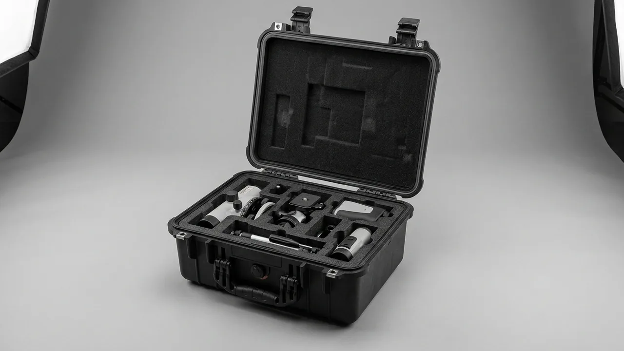
A field service engineer boards an early flight carrying a portable oscilloscope and calibration kit. A camera crew member travels with a body, lenses and a wireless transmitter in one piece of luggage. A fab equipment engineer packs a vacuum gauge, a standard resistor and a torque wrench into the same case. What these trips share is that the gear has to move with the person and be loaded and unloaded repeatedly across flights, shuttle vans and temporary workstations. One drop, one soaking shower of rain or one sudden pressure change can stop the day's work. A travel case exists to resolve the conflict between portability and engineering-grade protection. It is not a suitcase made thicker; it is a transport container redesigned so it can roll.
JUNZHIJIA frames the design principle plainly: the shell carries only the external loads coming from baggage systems, cargo floors and stacking, while the liner locates every item so it cannot shift or strike its neighbours — the two must be designed and accepted together. Reinforce either side alone and real travel will expose the gap: a thick shell with a fabric liner lets gear destroy itself inside, while a good liner in a soft shell gets crushed on the sortation line.
Table of Contents
- What a Travel Case Is: From Suitcase to Engineering Transport Container
- Shell Materials and Moulding Processes: PP, ABS and Rotomoulded LLDPE
- Handle and Wheel Systems: Balancing Low Weight Against Load Capacity
- Sealing: Where IP65 and IP67 Actually Sit in Travel Conditions
- Pressure Equalisation Valves: Managing Differential Pressure from Ground to Cruise Altitude
- Locks and Screening: TSA Locks, Customs Seals and Tamper Evidence
- Liner Compartments: Choosing Between Pre-Cut EPE and Die-Cut EVA
- Gear Zoning and Access Flow: High-Frequency and Low-Frequency Items
- Airline Size and Weight Compliance
- Baggage Handling Impacts and Stacking Loads
- Temperature, Humidity and Condensation Across Climate Zones
- Salt Spray and Multimodal Environmental Qualification
- Acceptance Criteria, Documentation and the Custom Process
- Frequently Asked Questions FAQ
- Conclusion and Related Reading
What a Travel Case Is: From Suitcase to Engineering Transport Container
A travel case sits at the intersection of luggage and transport containers. The first test is not appearance but whether it satisfies two conflicting constraints at once: it must roll and stay light, while its shell, seal and liner meet engineering specifications. Consumer trolley luggage prioritises looks and low weight, with walls of only 0.8 to 1.2 mm, a zipper for closure and a textile liner. Standard protective cases prioritise static storage and stacking, usually have no wheel system and weigh more. A travel case stacks the advantages of both, and the price is design difficulty and cost.
Look at the load path and there are four external inputs: sortation line drops of 0.5 to 1.2 m; multi-tier stacking inside baggage containers; single-point drag and throw by handlers; and continuous vibration during road legs. Internal inputs come from the gear itself — precision items are sensitive to acceleration, metal parts to impact, optical parts to humidity and mould. Selection should therefore start by writing down three datasets: total gear weight and centre of gravity, the allowable acceleration of the most sensitive component, and the number of transfer nodes plus the climate span of the whole trip.
| Item | Consumer trolley suitcase | Standard protective case (no wheels) | Trolley-style travel case |
|---|---|---|---|
| --- | --- | --- | --- |
| Wall thickness | 0.8–1.2 mm | 2.5–6 mm | 2.5–6 mm |
| Seal | Zipper or single-lip strip | Dual-lip gasket | Replaceable dual-lip gasket |
| Liner | Textile soft liner | Pre-cut EPE or EVA | Compartmented EVA plus removable dividers |
| Wheel system | Single-row castors | None | Twin-row reinforced castors |
| Pressure valve | None | Yes | Yes, essential for air travel |
| Typical empty weight | 2.8–4.2 kg | 3.5–6.5 kg | 4.5–7.5 kg |
Empty weight is the most underestimated figure: every extra 0.5 kg is carried through the entire trip and multiplied by each transfer leg. The engineering answer is to concentrate reinforcement at corners, wheel mounts and the handle mount, and let the remaining panels rely on ribs rather than uniform thickening. Estimate deflection on the top and side panels under five-tier stacking with a beam model or FEA, and hold it below 0.5 percent of the case diagonal.
Shell Materials and Moulding Processes: PP, ABS and Rotomoulded LLDPE
Three process routes dominate travel case shells. Injection-moulded PP offers uniform wall thickness, strong chemical resistance, fast cycle times and controllable cost, but low-temperature toughness has to come from compounding; plain PP loses impact strength noticeably around −10 °C. ABS delivers the best appearance accuracy and surface feel, which suits business-oriented finished cases, but weather resistance is weak and ultraviolet exposure yellows it. Rotomoulded LLDPE has almost no internal stress, no seams, walls of 4 to 6 mm and toughness down to −40 °C, and it handles irregular, large, one-piece shells especially well; the trade-offs are higher unit cost, lower dimensional precision than injection moulding, and a slightly textured surface.
What really determines life is rarely the base polymer alone but the supporting engineering. Ultraviolet stabilisation should be judged against at least 1,000 hours of xenon-arc or UV ageing for outdoor duty. Wall transitions matter: ribs on injection-moulded parts need generous fillets at the root, otherwise cracks start there on the first drop. Hinge and wheel-mount attachment must be resolved with moulded-in metal inserts or backing plates, because self-tapping screws driven into unsupported plastic loosen under repeated load. Low-temperature ageing should be verified by conditioning the case at −20 °C or −30 °C for four hours and dropping it immediately to check for brittle fracture.
| Property | Injection PP | ABS | Rotomoulded LLDPE |
|---|---|---|---|
| --- | --- | --- | --- |
| Typical wall | 2.5–4 mm | 2.5–3.5 mm | 4–6 mm |
| Low-temperature toughness | −20 °C with modification | −15 °C | −40 °C |
| Weather and UV resistance | Moderate, needs stabilisers | Poor | Good |
| Dimensional precision | High | Highest | Moderate |
| Small-batch cost | Medium-high, needs tooling | Medium-high | Low |
| Large-size moulding | Limited | Limited | Excellent |
For travel that crosses cold regions or high latitudes, rotomoulded LLDPE or modified PP is the safer route. If the case mostly moves between cities over short distances and appearance matters, an ABS shell with a properly engineered liner is sufficient. Check whether shell, wheel mount, handle mount and hinge sit in one consistent strength system, because the weakest link defines the protection level of the whole case.
Handle and Wheel Systems: Balancing Low Weight Against Load Capacity
The wheel system is the biggest structural difference between a travel case and a standard protective case, and the most common early failure point. Handles are usually 6061-T6 aluminium two- or three-stage telescopic tubes with 1.2 to 1.5 mm walls and three or four detents. Radial clearance between tubes should be held at 0.1 to 0.2 mm, and assembled wobble should stay under 2 mm, since that number decides whether the case tracks straight when pulled. The handle mount is a stress concentration: the reinforcement running from the base panel into the side wall must be continuous, or root cracks appear after sustained dragging at 40 kg.
Wheel selection should follow the real surface, not the catalogue photo. Airport and showroom floors are hard and smooth, where PU wheels run quietly with low rolling resistance. City pavements with expansion joints suit TPE wheels for more even damping. Gravel, construction sites and docks call for nylon cores with PU overmoulding, trading some rolling smoothness for cut resistance. Every 10 mm of extra wheel diameter improves obstacle clearance but raises the centre of gravity and reduces stability, so track width has to be adjusted at the same time.
| Surface | Recommended diameter | Wheel material | Bearing type | Reference life |
|---|---|---|---|---|
| --- | --- | --- | --- | --- |
| Airport and showroom floors | 50–60 mm | PU | 608ZZ steel bearing | Over 20 km |
| City pavements | 60–70 mm | TPE | Oil-impregnated bronze bush | 12–18 km |
| Gravel, site, dock | 70–75 mm | Nylon with PU overmould | Sealed steel bearing | 6–10 km |
A rough but practical model for load distribution: when a fully loaded case is pulled, about one third of the load passes through the handle into the wrist and two thirds sits on the wheel system. Wheel-mount bolts and inserts should be sized for at least 1.5 times the loaded weight with a dynamic factor on top. An 8 km mixed-surface loop covers most failure modes: tread separation, bearing noise, loss of bolt preload, detent failure and base panel deformation. Where de-icing salt or salt spray is expected, axles and bearings should use stainless steel or a validated coating.
Sealing: Where IP65 and IP67 Actually Sit in Travel Conditions
Under GB/T 4208 and IEC 60529, the first digit of an IP rating covers solids and the second covers water. IP65 is protected against water jets — a 6.3 mm nozzle at roughly 30 kPa and 12.5 L/min for three minutes — while IP67 is protected against temporary immersion, typically 1 m for 30 minutes. Both risks exist in travel. Rain driven sideways across an apron or platform matches IP65. A case lying in standing water on the ground or in pooled condensate inside a cargo hold matches IP67. The most common selection error is treating "I would never throw the case in the water" as a reason to skip IP67, when real failures usually come from prolonged accumulation coupled with negative pressure drawing water inward.
Gasket material and compression are decisive. EPDM offers good weathering and ageing resistance at moderate cost; silicone covers a wider temperature range but tears more easily; hardness usually sits at 55 to 65 Shore A. Three design points govern the gasket groove. Compression should be 25 to 35 percent of the gasket section height. Sealing face flatness should be held within 0.3 mm on injection-moulded parts, while rotomoulded parts need a thicker section to compensate for wider shrinkage variation. And clamp load must be balanced, because a difference between the hinge side and the latch side creates local leakage, so additional catch points are needed along the middle, with at least six in total.
In-plant verification splits into two levels. Type testing runs the IP65 jet and IP67 immersion procedures. Batch acceptance uses pressure decay: pressurise a sealed case to 20 to 30 kPa, close the valve and log the decay over 60 seconds, rejecting anything above the set threshold. Gaskets are consumables; cycling, ultraviolet exposure, oil and salt accelerate hardening, so replacement is normally scheduled at two to three years. Inspect the groove for scratches and deposits at the same time, as described in the guide to seal ring replacement and failure diagnosis, alongside the system-level IP67 design approach and the differences between IP65, IP66 and IP67.
Pressure Equalisation Valves: Managing Differential Pressure from Ground to Cruise Altitude
The pressure equalisation valve is the clearest technical dividing line between a travel case and ordinary luggage. In cruise the cargo hold is typically held at an equivalent altitude of 2,000 to 2,500 m, so absolute pressure outside the case is roughly 25 to 30 percent lower than at ground level, while hold temperature may fall below 0 °C. A fully sealed case with no valve develops a differential across that segment. Relative internal overpressure pushes the gasket outward; relative internal underpressure draws the gasket lip inward. Once a sealing lip has been pulled between the sealing faces, it can retain permanent deformation after landing and produce a slow leak.
The engineering answer is a waterproof breathable valve: a body combined with a PTFE or expanded PTFE membrane whose pore size is far smaller than a water droplet yet far larger than a gas molecule, so gas passes and water does not. Two parameters matter. The cracking differential pressure is normally designed between 0.15 and 0.35 bar; too high and the differential acts on the gasket first, too low and wind-driven rain can trigger it. The second is airflow capacity, calculated from internal volume and the expected rate of temperature change, otherwise internal pressure cannot track ambient and the valve is effectively decorative. The valve belongs in salt spray and ageing testing too, because grease contamination or salt crystallisation slowly degrades the membrane, as covered in the note on pressure equalisation valve operation and selection.
Locks and Screening: TSA Locks, Customs Seals and Tamper Evidence
In screening, a travel case faces two opposing requirements: it must resist tampering and theft, yet customs must be able to open it without destroying it. A removable solution is a TSA-accepted lock that customs can open with a master key while the owner is absent, plus a customs seal hole of 4 to 5 mm so a single-use seal can be threaded through. The seal number should be recorded in the accompanying documentation and checked against the record before opening at destination.
Latches and hinges are structural parts, not accessories. Latch load paths should be doubled so no single point carries the whole load. Hinge pins should be 304 or 316 stainless steel to avoid seizing in damp conditions, and metal bushings can be added where shear resistance is needed. Clamp load and catch count are tied to sealing performance: more catch points give more even gasket compression but make opening and closing heavier. Travel cases usually use six to eight catch points; cases longer than 900 mm should move to eight or ten, with an additional tension latch at the mid-point of the long side.
Another easily overlooked detail is external snagging. Sortation conveyors, belt side guards and baggage cart mesh can catch a protruding latch handle or handle button, dragging the case or tearing it loose. Latch profiles should therefore be low and rounded, handles should avoid a pronounced hook opening, and handle buttons are best recessed or ringed with a guard. These details have to be resolved at the structural design stage, not compensated by material choice.
Liner Compartments: Choosing Between Pre-Cut EPE and Die-Cut EVA
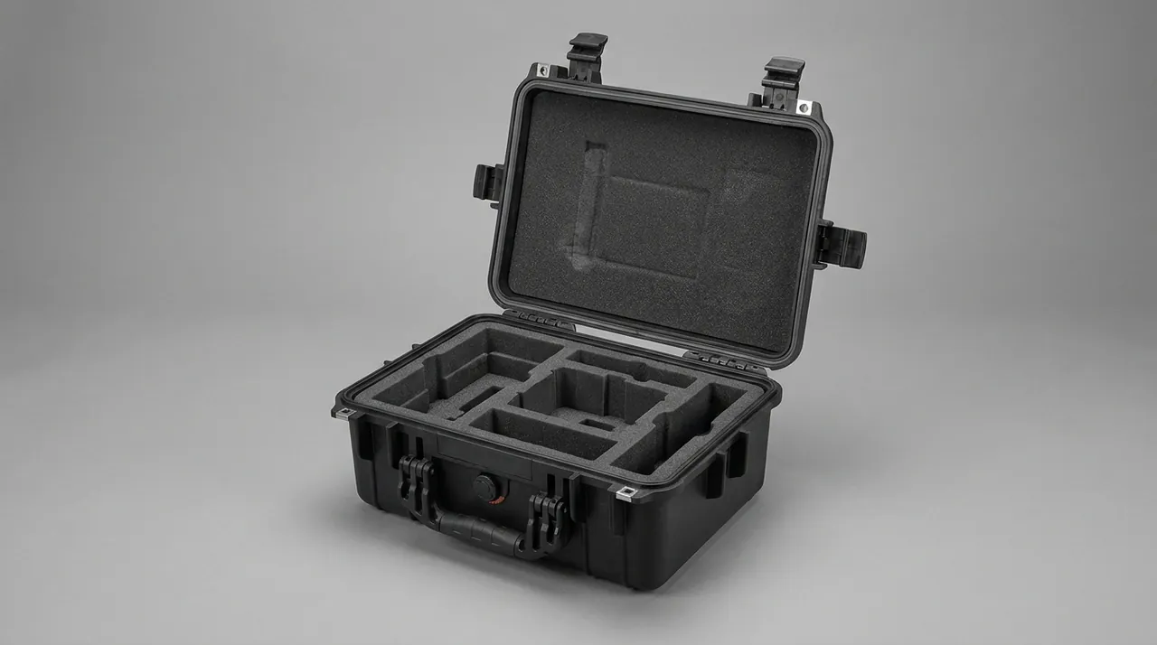
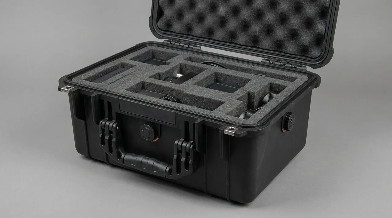
The liner passes load from the equipment surface into the shell and holds equipment in a defined position. The trade-offs between three common materials are clear. EPE pearl foam has low density at 25 to 35 kg/m³, good rebound, low cost and easy machining, suiting regular large items and positions that are loaded repeatedly, but it compresses permanently over time and loses positioning accuracy. EVA is dense at 60 to 90 kg/m³, dimensionally stable, can be die-cut or thermoformed precisely, and suits precision parts, lenses and frequently used slots. IXPE is cross-linked polyethylene with finer closed cells and very low water absorption, which helps on humid routes or where the insert is washed. A PU foam layer underneath adds energy absorption where needed.
In practice, all-one-material liners are rare. A better combination uses EVA on the top layer for location and appearance, EPE or IXPE below for absorption and levelling, with local reinforcement blocks at the corners and the base. Layering has a second benefit: when a piece of equipment changes size in a later iteration, only that layer has to be remade. For a fuller comparison, see protective case internal foam types and the EVA foam insert custom process.
| Material | Density kg/m³ | Compression set | Water absorption | Travel fit |
|---|---|---|---|---|
| --- | --- | --- | --- | --- |
| EPE | 25–35 | Medium | Low | Large regular items |
| EVA | 60–90 | Low | Low | Precision and optical items |
| IXPE | 33–60 | Low | Very low | Humid routes, washable |
| PU foam | 25–45 | High | Medium | Energy-absorbing base layer |
Liner clearance is often ignored. An interference fit of 1 to 2 mm between equipment and foam removes most micro-vibration without stressing the housing. Too much clearance lets equipment move inside the case, and once the foam has compressed to its limit the amplified acceleration transfers straight into the shell. For items with a high centre of gravity, a compression block in the lid should hold the item from both directions once the case is closed.
Gear Zoning and Access Flow: High-Frequency and Low-Frequency Items
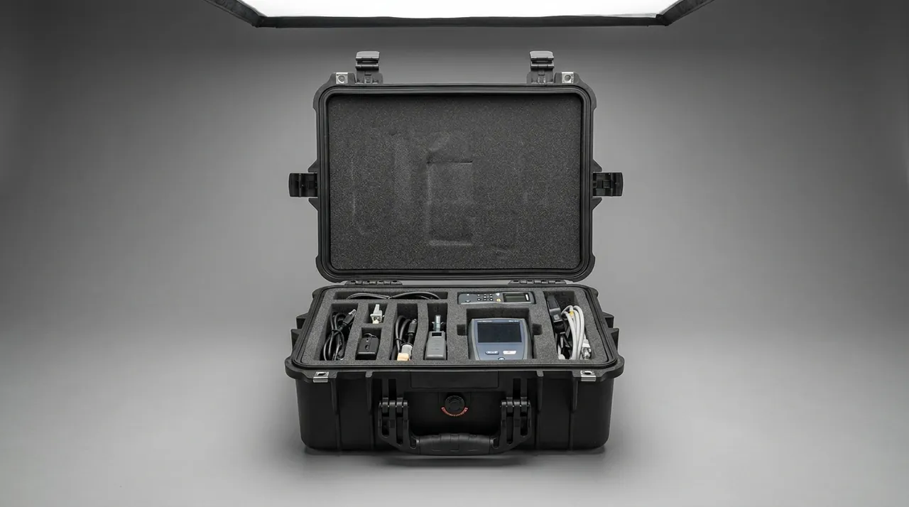
Access frequency during a trip is highly uneven. Power adapters, multimeters, laptops and common cables may be taken out a dozen times a day, while spare lenses, calibration artefacts and dedicated fixtures may stay untouched for the whole journey. If the liner is laid out only by size and not by frequency, taking out a small item means lifting the whole upper layer, which is inefficient and raises the risk of drops and knocks over time.
A sound zoning logic has three tiers. The top tier is the high-frequency zone, sitting at the top of the packed case so it can be reached as soon as the lid opens, with no locks or straps, or at most an elastic net. The middle tier is the task zone, laid out in the order the day's work flows, left to right and top to bottom, creating a fixed sequence. The bottom tier is the low-frequency and spares zone, isolated with removable dividers or a separate well that can be lifted out as a unit.
The value of a removable divider system shows up in dynamic use: one case can carry measuring equipment in the morning and samples or tools in the afternoon by moving dividers and foam blocks rather than replacing the liner. Matching a zoning plan to internal volume can be estimated with simple area and height ratios; see removable divider system design and the volume accounting method in toolbox capacity calculation.
Airline Size and Weight Compliance
For a travel case to actually fly, dimensions and weight must be locked into airline rules at the design stage. Most carriers cap cabin baggage at roughly 55 × 40 × 20 cm with a linear dimension of 115 cm and a single-piece weight of 7 to 10 kg. Checked baggage is usually capped at 158 cm linear with a standard 23 kg tier; some carriers offer a 32 kg heavy tier subject to advance request and a surcharge. Anything above 158 cm is oversized, routed through a special channel with longer transit times and a higher damage probability. Lithium batteries installed in equipment must travel in the cabin and cannot be checked. That is a hard requirement, and it directly shapes the liner layout, because the battery must be separable from the equipment body quickly.
Weight budgeting is another trap: the case itself is relatively heavy, so a loaded case crosses the 23 kg line easily. Empty weight and maximum payload should be marked on the outside, and the liner should carry a weight budget table for the baseline configuration so users know how much spare capacity remains. Where a trip switches between the 23 kg and 32 kg tiers, a modular liner lets a detachable spares well come out, shedding several kilograms at once.
| Baggage class | Linear limit | Single-piece weight | Notes |
|---|---|---|---|
| --- | --- | --- | --- |
| Cabin | 115 cm or less | 10 kg or less | Must clear screening, batteries in cabin |
| Standard checked | 158 cm or less | 23 kg | Most carriers |
| Heavy checked | 158 cm or less | 32 kg | Advance request required |
| Oversized | Above 158 cm | Per carrier rules | Dedicated channel, higher risk |
Baggage Handling Impacts and Stacking Loads
The dynamic inputs from an airport baggage system are harsher than designers expect. Cases fall from the chute to the belt, are squeezed by guide plates at corners, and are stacked three to five tiers high inside containers. Stacking creates a particularly important top-side static load. If a loaded case weighs 35 kg and is stacked five high, the bottom case top face has to carry about 140 kg distributed or off-centre, which is already near the limit of many non-engineering cases.
There are three structural responses. First, the top and bottom faces need a rib array, ideally at 60 to 90 mm pitch, with thickened corners or metal inserts because stacking loads travel down through the corners. Second, the side walls need hoop reinforcement around the middle to resist belt side-guard compression. Third, the base needs continuous reinforcement near the wheel mounts, since the combined stacking and dragging load cracks there first. On the liner side, the acceleration transmitted to equipment must be controlled; for general electronics a peak target of 40 G is reasonable, while gear containing precision optics or mechanisms needs a stricter target, achieved with thicker foam or a two-stage cushion, as discussed in the note on combined shock and seal design.
Temperature, Humidity and Condensation Across Climate Zones
The classic failure on cross-climate trips is not water ingress but condensation. After a case has spent hours in a cold hold or a winter outdoor setting, moving quickly into a warm humid room leaves the inner walls and equipment surfaces below the dew point, and water vapour condenses on them. The damage is often delayed: nothing looks wrong that day, then corrosion appears on a circuit board or mould on an optical surface days later.
Control has three levels. At material level, the liner should use low-absorption materials; IXPE and EVA both outperform open-cell foam. At structural level, closed dead spaces should be avoided so moisture reaches the desiccant instead of sitting in a crevice. At operational level, desiccant plus a humidity indicator card is the most direct measure. Silica gel or molecular sieve is sized from internal net volume and trip duration; roughly 10 to 20 g of silica gel per 10 L of net volume covers several weeks. Indicator cards are graduated at 10 to 60 percent; read the card before unpacking, and a reading above 40 percent means either the seal or the desiccant capacity is already insufficient.
There is also a practical rule for temperature transitions: let the case stand indoors for one to two hours after moving from cold to warm, so internal and external temperatures converge before the lid is opened, which significantly lowers the condensation risk.
Salt Spray and Multimodal Environmental Qualification
Travelling equipment does not always sit in air-conditioned spaces. Coastal projects, island construction sites and samples moving by LCL sea freight all expose cases to chloride. Under the GB/T 10125 neutral salt spray test, common durations are 48, 96, 240 and 480 hours, typically used to rank the corrosion resistance of hardware, coatings and metal inserts. For a travel case, the critical metal parts are wheel axles, bearings, hinge pins, inner handle tubes and latch springs, because functional degradation usually precedes visible change: a seized bearing sharply raises rolling resistance, and a corroded handle detent jams.
Material guidance follows experience. Inland and ordinary outdoor duty can use 304 stainless steel. Coastal, island and de-icing-salt routes justify moving to 316. Parts that cannot change material should be upgraded with plating or coating, with particular attention to edge coverage, since corrosion usually starts at edges. Salt spray testing ranks schemes; it cannot be extrapolated directly to field life and does not support any certification claim.
Multimodal verification is better handled as a whole-packaging evaluation. The ISTA series and the GB/T 4857 series — vibration, shock, stacking and drop — assess how a packed case behaves in transport. Air freight also requires attention to low-pressure effects on a sealed cavity, which links directly to the pressure equalisation valve. ASTM D4169 provides a fuller distribution cycle model for combined conditions. A recommended sequence runs single-factor tests first to locate weak points, then a full cycle test under combined conditions, then freezing the conclusions into an inspection specification. For long sea legs and extended storage, see sea freight notes for outdoor cases.
Acceptance Criteria, Documentation and the Custom Process
Incoming acceptance for a travel case should be a written checklist. The appearance check covers through-wall cracks, whitened ribs and scratches in the seal groove. The functional check covers consistent latch feel after closing, reliable handle detent at every stage, and wheel rotation free of noise or axial play. The seal check is a pressure decay test as described earlier. The liner check covers interference fit and extraction force, and insertion must not scrape the housing surface.
Documentation should include four items: a packing list and liner layout drawing identifying which item belongs in each slot, the initial humidity indicator reading and the reading recorded on arrival, inspection records for the seal and pressure valve, and a consumable replacement schedule. These documents matter when a dispute arises: the layout drawing shows which layer lost location, and the inspection record separates a factory defect from transport damage.
A custom project normally runs in four steps: requirement confirmation covering the equipment list, external dimensions, protection level and climate span; structural and liner design including foam selection and compartment layout; prototyping and small-batch validation with drop, spray, pressure decay and rolling tests; and then production with incoming inspection frozen. Colour, printing and markings are the easy part. Real lead time is driven mainly by liner tooling and structural revisions. The boundary between minimum order quantity and tooling cost is discussed in custom case MOQ baseline.
Frequently Asked Questions FAQ
Q: Does a travel case always need a pressure equalisation valve, and can it be dropped for purely overland trips?
A: For trips that stay on the ground and never cross high altitude, omitting the valve is technically possible, but it is still not advisable. The valve does more than manage flight differential pressure; it also handles internal pressure swings caused by temperature change across climate zones. Consider a case left outdoors at −15 °C in winter and then loaded into a sealed vehicle at 25 °C. Internal pressure rises as the case warms, and with a good seal and no relief path the gasket can be pushed out of its groove, reducing clamp load. Overland transport also subjects the case to sustained vibration that slightly deforms the shell, and a valve reduces how much the differential amplifies that deformation. Because the cost difference is small relative to the risk, JUNZHIJIA fits the valve as standard and offers a plugged screw seat for customers who genuinely need a sealed configuration, so a breathable membrane core can be swapped in later when air travel starts.
Q: Is an IP65 travel case genuinely adequate when transferring gear across an apron in the rain?
A: For most rainy apron scenarios IP65 is sufficient, provided the case stays upright and the jet does not hit the seal groove directly. The IP65 test condition is a 6.3 mm nozzle at roughly 30 kPa and 12.5 L/min for three minutes, which already covers moderate rain combined with wind pressure. Real risk comes from three departures from that condition: the case lying on its side so the groove collects standing water; water pooling on the ground around the base and being drawn in by negative pressure; and rain falling directly into the liner when the case is opened. Covering the first two means specifying IP67 and ensuring the groove has drainage channels and a water lip. The third is an operational matter, best handled by opening the case under cover or adding a fold-back rain flap inside the lid. For routes that involve both aprons and boat transfers, IP67 is the sensible default rather than an upgrade, and it also covers tropical downpours where standing water around the base is routine. A good travel case also keeps small items such as chargers and adapters in their own pocket, so they do not scratch the main contents and can be found without emptying the whole case at the airport.
Q: For travel use, should I choose pre-cut grid foam or a custom die-cut EVA liner?
A: It depends on how often the equipment changes and how tight the precision requirement is. If the gear has regular shapes, changes often and you want to rearrange slots freely, pre-cut EPE grid foam is more flexible and cheaper; the downside is that cell edges collapse after repeated insertion, positioning accuracy degrades and there is no base cushion compensation inside each cell. If the load includes lenses, optical assemblies or precision instruments, or items are inserted many times a day, custom die-cut EVA is the better choice because its locating faces are accurate, edges are clean, it sheds little debris and each item can be designed with its own interference value. A middle path is layering: EVA on top for location, EPE or IXPE below for absorption and levelling, so a size change only means remaking the top layer. Decide the liner replacement cycle first; if it is shorter than the equipment refresh cycle, favour removable dividers and modular foam instead of a fully bonded insert.
Q: Where should equipment with built-in lithium batteries sit in a travel case, and can it be checked in?
A: Lithium batteries must generally travel in the cabin and should not go into a checked travel case. That rule feeds directly into liner zoning: if the equipment body must be checked, design it so the battery separates quickly, allowing the user to split the assembly in a few tens of seconds on site. When the battery travels with the passenger, the liner should provide a dedicated well with EVA locating it separately so it cannot touch metal parts or tools and short circuit, and terminal caps or dust covers are advisable on each pack. If the equipment is a one-piece design with a non-removable battery, the whole unit travels in the cabin, and the size and weight limits for cabin baggage then constrain the case and liner design. Bring those limits into the design review rather than discovering at packing time that the case exceeds them, because at that point the only options are leaving gear behind or paying for oversized handling. Because checked luggage is handled by machines and by hand, the case outline should be free of straps and loops that can snag on a conveyor, and the latches should sit flush so they are not forced open by a side impact.
Q: How should desiccant quantity be estimated for travel across climate zones?
A: The common method is to work from internal net volume, typically 10 to 20 g of silica gel per 10 L of net volume for a trip lasting several weeks. For routes that include tropical humidity or a sea leg, take the upper figure and carry spare desiccant. Two cautions apply. Net volume is not the external case volume; subtract liner, equipment and structural parts, and it is usually only 40 to 60 percent of external volume. And desiccant has a finite capacity, consumed faster the longer the case is away and the more often it is opened, so the humidity indicator card is the direct basis for deciding whether replacement is needed. If the reading exceeds 40 percent, replace the desiccant before the next closure and check the gasket for deformation or trapped debris at the same time. Records of the reading before dispatch and after arrival turn a vague worry into a trend that can be reviewed across shipments. For repeat trips it is worth keeping a packing list fixed to the case lid, so the same load is packed each time and a missing item is noticed before departure rather than at the destination.
Q: My handles and wheels keep failing. Is that a material problem or a usage problem?
A: In most cases it is a combination of low design load assumptions and discontinuous structure, not material selection alone. There are three common failure paths: the wheel mount root cracks after loaded dragging because reinforcement is not continuous; the axle corrodes where surface treatment is inadequate, rolling resistance rises and the bearing is destroyed by force; and the inner handle tube wobbles because radial clearance is too large, so the detent mechanism fails under repeated impact. The fixes are to run reinforcement continuously from the base panel into the side wall, to use stainless steel or validated plating on axles and bearings with salt spray verification, and to hold handle clearance at 0.1 to 0.2 mm with assembled wobble under 2 mm. An 8 km mixed-surface loop will normally expose all three problems in advance, and the wheel bearings should be opened afterwards to confirm no water or grit has passed the seal. If failures persist after those changes, check whether the case is being routinely overloaded beyond its marked maximum payload, because a case rated for 30 kg that travels at 45 kg will shorten wheel life disproportionately.
Q: How many stacking tiers should be designed for, and how do air and road differ?
A: Air scenarios are usually estimated at three to four tiers, while road and warehouse scenarios should be estimated at five tiers with margin. The calculation multiplies single-case loaded weight by tier count to get the bottom-case load: a 35 kg case stacked five high puts about 140 kg on the top face of the lowest case. The difference is that air stacking is short but handling impacts are severe, whereas road stacking lasts days or even weeks, and long-term static load causes plastic creep, so deformation accumulation over time has to be considered for road duty. Structurally, reinforce the top-face corners with metal inserts, keep rib pitch at 60 to 90 mm, and mark the maximum stacking tiers on the outside of the case. Where several cases are strapped together into a unit load, the straps themselves must be rated and the unit must be stable enough that handlers do not separate it. On the road, a unit load also needs to be restrained inside the vehicle, because a stack that slides during braking transfers far higher shear into the bottom case than stacking alone does. A small pressure-equalisation valve is worth having on a hard travel case, since without it the altitude change between departure and arrival can make a well-sealed case hard to open and stress the gasket at the rim.
Q: How often should travel case gaskets be replaced, and how do I judge?
A: Two to three years is the usual recommendation, or a defined cycle limit, depending on frequency and environment. Three indicators govern the decision. Visually, the gasket hardens, takes a permanent set, shows surface cracks or rebounds slowly. Functionally, a pressure decay test at 20 to 30 kPa shows decay beyond the threshold within 60 seconds. In use, the case becomes harder to close, or the humidity indicator card keeps reading high. It is worth stressing that a gasket is a consumable rather than a lifetime part, and oil, ultraviolet light, salt spray and low temperature all accelerate ageing. When replacing it, check groove flatness and scratches at the same time, because groove damage cannot be fixed by a new gasket and needs local repair or a return to the factory. Keep the replacement record with the case so the next inspection has a date to work from.
Conclusion and Related Reading
Write both the external load path and the internal constraints into one plan, then let climate span and transport mode set the protection level and leave appearance for last.
Related Reading