

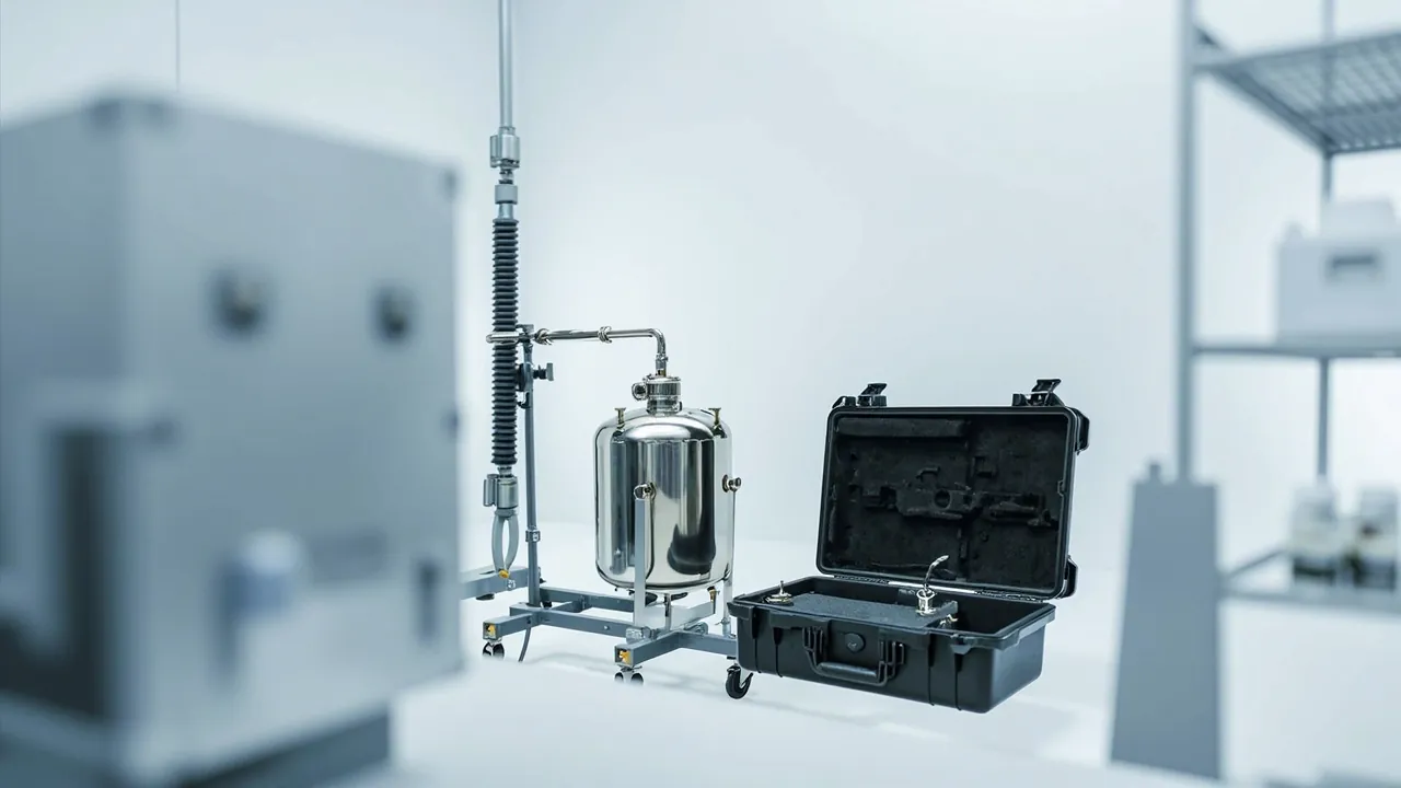
A bioreactor and fermentation parts case solves a harder problem than a general equipment box: agitator components bend, sensor probes bruise, and every product-contact surface is vulnerable to contamination. The answer compresses into one line: protection for bioprocess components must preserve aseptic boundary integrity and measurement accuracy at the same time. If either is degraded in transit, the next cultivation batch shows it as contamination risk, drifting dissolved oxygen control, or a failed scale-up.
The pain points in a bioprocess plant are consistent. An agitator shaft comes off the vessel and stands against a wall. The mechanical seal assembly goes into a plastic bag. pH and dissolved oxygen probes come out and sit in beakers of storage solution, rocking around during transport. Single-use sensors and transmitters are mixed loose in a tote. That works for a short move by one trained operator. It fails as soon as the route involves inter-site transfer, contracted sterilisation, third-party logistics or export. Then the damage multiplies: shaft straightness beyond tolerance, cracked probe membranes, moisture in connectors, scratches on sealing faces that prevent hold-pressure testing after steam sterilisation.
This article is written for technical, equipment and procurement staff in biopharmaceutical and fermentation operations. It covers the aseptic boundary, material compatibility, sealing class, vibration design, sterilisation workflow integration, acceptance and traceability, with comparison tables and checklists you can put straight into a specification. JUNZHJIA supplies custom inserts, OEM/ODM programmes and model-specific seal configurations for bioprocess component cases, and the structures described here come from that project experience.
Table of Contents
- 1. Why Bioprocess Components Need a Dedicated Protective Case
- 2. Agitator System Components: Shaft, Impeller and Mechanical Seal Protection
- 3. Sensors and Probes: Protecting pH, DO, Conductivity and Temperature Elements
- 4. Differentiated Protection for Single-Use and Reusable Components
- 5. Cleanliness and Biosafety Requirements for the Case
- 6. Material Compatibility: 316L Passivation, Seal Materials and Sterilisability
- 7. Sealing Class: IP65/IP67, Pressure Equalization and Sterile Bag Compatibility
- 8. Vibration Design: Agitator Shaft Straightness and Long-Item Transport
- 9. Temperature Control: Post-Sterilisation Cooling, Cold Chain and Low-Temperature Storage
- 10. Cleaning and Sterilisation: Coordinating with CIP/SIP
- 11. Custom Insert Design: From Parts List to Dedicated Probe Pockets
- 12. Acceptance, Traceability and Validation Documents
- 13. Purchasing Decisions, Use and Maintenance
- Frequently Asked Questions
- Conclusion & Related Reading
1. Why Bioprocess Components Need a Dedicated Protective Case
Components from bioreactors and fermentation systems share three characteristics: extremely demanding product-contact surfaces, geometry that directly determines process performance, and operation inside an aseptic or controlled environment. Those three rule out general-purpose totes.
First, the aseptic boundary must not be compromised. Vessel sterility depends on the integrity of a whole boundary: vessel body, agitator shaft seal, headplate connections, sampling valve and sensor ports. Once a component is scratched, dented or deformed in transit, the sealing faces no longer mate after reassembly. Hold-pressure testing after steam sterilisation fails, or it passes and then weeps slowly during a long cultivation. Problems of this kind are extremely difficult to localise in a contamination investigation, and expensive.
Second, measurement accuracy does not come back. pH, dissolved oxygen, conductivity and temperature probes are inline analytical instruments. Their sensing elements, whether glass membrane, fluorescent film or reference electrode junction, are acutely sensitive to mechanical shock and to drying out. A damaged probe does not fail immediately. It responds more slowly, drifts further and fails calibration more often, and process control eventually deviates.
Third, scale-up amplifies the risk. Moving from seed to production scale, power input, mixing time and oxygen transfer coefficient all depend on the geometric consistency of the agitator system. A change in blade angle, impeller deformation or shaft bow alters the hydrodynamics and pushes the scale-up batch away from the development batch.
A simple test: if damage to the component would trigger a contamination investigation, a batch record deviation or process revalidation, it deserves a dedicated protective case.
Compared with a general equipment box, a bioprocess component case must deliver four things at once: physical protection, environmental isolation, sterilisability or disinfectability, and traceability. Sterilisability is the one most often forgotten. If the liner cannot survive a sterilisation route and cannot work with a sterile bag, the case itself becomes a contamination source.
2. Agitator System Components: Shaft, Impeller and Mechanical Seal Protection
The agitator system carries the highest mechanical risk in a bioreactor. Grouping by weak point:
| Component | Typical size range | Main weak point | Failure mode | Protection priority |
|---|---|---|---|---|
| --- | --- | --- | --- | --- |
| Agitator shaft | 20 to 150 mm diameter, 500 to 3000 mm long | Straightness, bearing journals, shaft end taper | Bending, journal denting | Full-length support, multi-point cradles, no cantilever |
| Impeller / blade assembly | 100 to 1200 mm diameter | Blade angle, weld root | Blade deformation, weld cracking | Angle protection, root support |
| Mechanical seal | Shaft seal assembly | Stationary and rotating face flatness | Face scoring, spring deformation | Independent fixing, isolated faces |
| Magnetic coupling | Inner and outer magnet sets | Thin-walled containment shroud, magnets | Shroud denting, magnet fracture | Axial restraint, magnet separation |
| Agitator gearbox | Gear unit | Input and output shafts, oil seals | Bearing shock damage, seal weeping | Damped support, attitude fixing |
| Couplings and sleeves | Various | Mating bore | Bore galling, keyway damage | Bore plugs, separate storage |
The agitator shaft is the hardest item in the whole set, for a simple reason: it is long, slender and has limited bending stiffness. For carbon steel or 316L, once the span-to-diameter ratio exceeds a certain value, self-weight plus transport vibration can produce permanent bow. Four rules apply:
- Full-length multi-point support, with cradle spacing calculated from shaft stiffness, in practice no more than one third of shaft length, and always including both ends.
- No cantilever spans. Overhang beyond the outermost support should stay within two to three shaft diameters; anything longer needs an auxiliary cradle.
- Fixed attitude. Horizontal transport is preferred; vertical standing is unstable because of the high centre of gravity.
- Isolate finished surfaces. Journals, bearing seats and seal seats are mating surfaces and must be separated by soft interleaving or protective sleeves, never contacting a hard cradle directly.
For the mechanical seal assembly, the focus is on the faces. Stationary and rotating seal face flatness is specified at optical-flat levels. Any hard particle embedded between them, or any rubbing, causes irreversible damage. The correct practice is to fix the rotating and stationary rings separately in their own pockets so the faces never touch, keep spring assemblies in a relaxed state to avoid fatigue from long compression, and store the auxiliary O-rings separately so they are not flattened.
Magnetic couplings are a special case. If the inner and outer magnet sets come close during transport, magnetic attraction can pinch the containment shroud. Protection requires magnetic isolation: fix inner and outer sets in separate pockets with sufficient spacing, or place a non-magnetic separator between them, and mark magnet orientation. This must be written into the packing work instruction, because otherwise pinch injuries happen at the packing bench.
3. Sensors and Probes: Protecting pH, DO, Conductivity and Temperature Elements
Sensors are the sensitive end of inline analytical instrumentation, and the most likely to emerge "looking fine but already drifted".
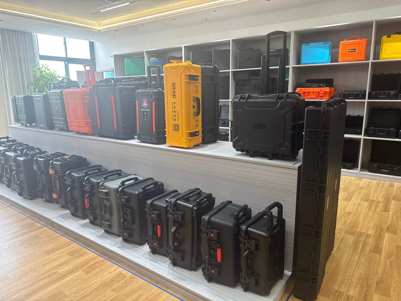
| Probe type | Sensing element | Main risk | Pre-transport treatment | Insert requirement |
|---|---|---|---|---|
| --- | --- | --- | --- | --- |
| pH probe | Glass membrane bulb, reference junction | Bulb fracture, junction blockage or drying | Fit storage solution sleeve, keep wet | Vertical individual pocket, tip-over prevention |
| Dissolved oxygen probe | Fluorescent film or polarographic electrode | Film scratching, electrolyte loss | Fit protective cap per supplier instruction | Floating face, soft bearing |
| Conductivity probe | Cell-constant sensitive element | Surface contamination, geometric deformation | Clean and dry, or per supplier instruction | Individual pocket, no squeezing |
| Temperature probe | PT100 / PT1000 element | Lead pulling, sheath deformation | Coil and restrain leads | Lead channel, minimum bend radius |
| Pressure / level transmitter | Diaphragm, capillary | Diaphragm overpressure, capillary kinking | Fit port caps | Axial fixing, generous bends |
| Transmitter and junction box | Electronics, connectors | Moisture ingress, connector deformation | Moisture barrier packing | ESD-safe insert with desiccant |
Six rules that work in practice:
- Store probes vertically, or in the attitude specified by the supplier. A pH glass bulb lying on its side for weeks leaves the storage solution unevenly distributed and dries the junction locally.
- Keep storage solution with the probe. Dry transport causes permanent reference electrode drift. The storage sleeve must be a sealed design and firmly fixed so leakage cannot corrode the case or adjacent components.
- Keep the sensing face floating. Fluorescent films, glass membranes and diaphragms must not touch any hard material and must not carry sustained pressure.
- Coil cables to the minimum bend radius. Cables held at a small radius for long periods fracture the shield and induce signal drift; the coiling radius should be six to ten times the cable outer diameter.
- Protect connectors separately. Connector pins bend easily and should be isolated with caps or foam pads, kept away from metal components.
- Address moisture and static for transmitters. Moisture reduces insulation resistance and ESD causes latent damage, so provide a desiccant compartment and an antistatic liner.
A practical acceptance criterion: after a 750 mm corner drop plus random vibration on the loaded case, open it and inspect. If the probes show no visible damage and calibration slope remains within the supplier's factory tolerance, the insert design is fundamentally sound.
One further point deserves emphasis. Probes should complete a pre-transport treatment sheet before packing: clean, add storage solution, fit caps, and record serial number and last calibration date. This sheet maps one to one onto the pocket numbers inside the case and can be filed directly into the asset register.
4. Differentiated Protection for Single-Use and Reusable Components
Bioprocessing makes heavy use of single-use systems including single-use sensors, mixing bags, tubing assemblies and connectors. Their protection logic is completely different from reusable stainless components.
| Category | Representative items | Key risk | Protection objective | Recommended approach |
|---|---|---|---|---|
| --- | --- | --- | --- | --- |
| Reusable stainless components | Shaft, impeller, mechanical seal, probe housing | Deformation, scratching, contamination | Preserve geometry and cleanliness | Rigid case + custom insert + replaceable contact layer |
| Single-use sterile components | Single-use sensors, mixing bags, aseptic connectors | Packaging puncture, barrier failure | Keep the sterile barrier intact | Rigid outer case + double bagging + burr-free liner |
| Precision electronic components | Transmitters, controllers, weighing modules | Moisture, static, vibration | Stable electrical performance | Antistatic liner + desiccant + damping |
| Consumables | Gaskets, clamps, fittings, seals | Mixing up, contamination, distortion | Segregation and cleanliness | Divided pockets + clean bags + numbering |
The protection objective for single-use items is the integrity of the sterile barrier, not the item itself. Once the outer packaging has a pinhole, a micro-crack at a fold, or a peeled seal edge, the barrier has failed. The transport system therefore has to:
- Eliminate sharp edges and corners. Neither the case interior nor the liner may present any protrusion, screw head or burr capable of puncturing packaging.
- Follow a double-bagging logic. The inner layer is the supplier's sterile barrier, the outer layer is a protective bag, and the case provides only mechanical protection and dust and water exclusion.
- Avoid compression stacking. A folded single-use mixing bag is bulky and pressure-sensitive, so it should lie flat in a single layer or be separated by layer plates rather than stacked under load.
- Control temperature and humidity. Some single-use components are heat-sensitive, so keep the case away from heat sources in transport and storage and watch for internal condensation.
Single-use components also carry expiry dates. The case label area should therefore be designed as a replaceable label card so batches and expiry dates can be tracked, avoiding write-offs from stock that is never drawn down.
5. Cleanliness and Biosafety Requirements for the Case
A bioprocess plant operates under two parallel sets of requirements, cleanliness classification and biosafety level, and the case has to satisfy both.
| Area of use | Cleanliness reference | Biosafety level | Recommended case configuration | Key control point |
|---|---|---|---|---|
| --- | --- | --- | --- | --- |
| Aseptic core | ISO 14644 Class 5 / GMP Grade A, B | Process dependent | Fully enclosed body + wipeable interior + sterile transfer bag | No fibre or particle release |
| Classified clean area | ISO Class 7 / GMP Grade C | Commonly BSL-2 | IP65 or better + alcohol-wipeable liner + desiccant | Surfaces fully cleanable, no dead corners |
| Controlled non-sterile area | ISO Class 8 / GMP Grade D | BSL-1, BSL-2 | IP54 to IP65 + moulded foam insert | Cleanable and traceable |
| Biosafety laboratory | Per laboratory requirement | BSL-2, BSL-3 | Fully sealed + disinfectable interior + leak-free construction | Disinfectant-resistant surfaces, no liquid traps |
| Workshop and spares store | Not applicable | Not applicable | IP65/IP67 + corrosion-inhibiting liner | Must be cleaned before entering classified areas |
GB 50457, the Chinese design standard for pharmaceutical industrial cleanroom facilities, requires separation of material and personnel flow and preservation of pressure differential and cleanliness through transfer. The case is effectively a mobile clean boundary. Its external wipeability decides whether an extra outer wrap is needed, and its sealing class decides whether external particulate is carried into the classified area during transfer.
Where biosafety requirements apply, three additional points matter:
- No liquid-trapping geometry. Residual liquid must not spill or form aerosols while the case is handled.
- Gaskets and liners must resist common disinfectants, including chlorine-based agents, peracetic acid and alcohols, without cracking under repeated wiping.
- External surfaces must be fully wipeable, including recesses, handles and the area around latches, so no disinfection blind spots exist.
Where EU GMP Annex 1 sterile process compliance applies, every material entering a Grade A or B zone needs a defined sterilisation or disinfection route. The case normally acts as the transfer container disinfected in the anteroom, so its materials must survive repeated wiping with isopropanol, hydrogen peroxide and quaternary ammonium compounds without cracking, blooming or plasticiser release.
6. Material Compatibility: 316L Passivation, Seal Materials and Sterilisability
Material selection is where hidden losses creep into bioprocess component cases.
Case body materials compare much as they do in pharmaceutical applications. PP offers good chemical resistance and low water absorption. ABS gives high stiffness and a wipeable surface but needs alcohol compatibility validation. HDPE is tough but marks easily. Glass-filled engineering plastics offer high strength but require confirmation that fibre is encapsulated. Aluminium-magnesium alloy is strong but needs corrosion treatment and should not contact stainless directly, to avoid galvanic corrosion.
Surface treatment of stainless components is the key issue. Grade 316L is widely used in bioprocessing and its corrosion resistance depends on an intact passive layer. If it sits in prolonged contact with chlorine-bearing materials, or in a humid sealed environment, the passive layer breaks down and pitting begins. Therefore:
- Liner materials should be sulphur-free, chlorine-free and low-outgassing; avoid regrind foam.
- Provide a humidity control provision such as a desiccant compartment or an optional sealed cavity.
- Separate components with non-woven fabric or clean-grade PE bags, not ordinary VCI paper.
- Where welds, electropolished surfaces or specified internal roughness Ra are involved, the contact layer should be softer to avoid any abrasion trace.
Seal material matters more in bioprocessing than in general industry because it touches both sterilisability and biocompatibility.
| Seal material | Temperature range (typical) | Sterilisation routes | Compatibility notes | Typical location |
|---|---|---|---|---|
| --- | --- | --- | --- | --- |
| Silicone (VMQ) | -50 to 200 C | Steam, dry heat, irradiation | Good biocompatibility, withstands repeated sterilisation | Sensor ports, sampling ports |
| EPDM | -40 to 150 C | Steam, irradiation | Good water and steam resistance, moderate oil resistance | Vessel ports, pipe clamps |
| FKM (fluororubber) | -20 to 200 C | Steam | Strong chemical resistance, biocompatibility needs assessment | Mechanical seal auxiliary rings |
| PTFE encapsulated | -60 to 260 C | All common routes | Most inert; elasticity depends on the core | High-cleanliness wetted locations |
| NBR | -30 to 100 C | Limited | Generally not recommended for bioprocess | Non-wetted locations |
The GB 4806 series on food-contact materials and articles is not mandatory in bioprocessing, but where a case doubles as a container for raw materials, media or excipients, its low-migration, low-odour and heavy-metal-free requirements are a useful reference.
7. Sealing Class: IP65/IP67, Pressure Equalization and Sterile Bag Compatibility
Sealing class is determined under IEC 60529 and its Chinese equivalent GB/T 4208.
| Class | Dust | Water definition | Typical bioprocess scenario | Notes |
|---|---|---|---|---|
| --- | --- | --- | --- | --- |
| IP54 | Limited dust protection | Splash resistant | Short in-plant transfer | Unsuitable near washdown areas |
| IP65 | Dust tight | Jet resistant | General component transport, around CIP areas | Most common |
| IP67 | Dust tight | Short immersion, 1 m / 30 min | Cross-zone transport, wet loading, cold chain periphery | Pair with a pressure equalization valve |
| IP68 | Dust tight | Continuous immersion | Special requirements | High cost, rarely necessary |
The value of a pressure equalization valve is often underestimated in bioprocess applications. A fully sealed case develops an internal-to-external pressure differential as temperature changes. Rising temperature bows the lid and loads the latches; falling temperature creates vacuum, making the lid hard to open and sucking the gasket out of shape. More importantly, when a differential exists, opening the lid quickly produces an air exchange that draws particulate from the external surface into the case, directly affecting environmental monitoring during cleanroom transfer. A pressure equalization valve uses a hydrophobic and oleophobic microporous membrane to breathe slowly while preserving IP65 or IP67. The principle and selection logic are covered in how the case pressure equalization valve works and how to select it.
Working with sterile bags is a bioprocess-specific requirement. Two approaches dominate:
- Bag inside the case. Components go into a clean bag, the bag mouth is folded outward over the case rim, then the lid closes. The advantage is that only the bag is handled on removal, and the case need not enter the classified area.
- Bag over the case. After external wiping and closing, the whole case is bagged, then surface disinfected in the anteroom before transfer. The advantage is that the external surface is never directly exposed.
The two approaches impose different requirements. Bag-inside needs a smooth, burr-free cavity so the bag cannot be punctured. Bag-over needs a clean external form with no protruding handles to snag and no gasket rolled outward to form a pocket.
Replaceability of seals and hinges matters for the same reason. The gasket is a wear item and replaceability determines whether the case lives for years. Hinge pins and latches set the opening cycle life. The structure is explained in toolbox hinge, latch and seal structure explained, and seal material differences are compared in protective case seal materials compared.
8. Vibration Design: Agitator Shaft Straightness and Long-Item Transport
Vibration design for bioprocess components concentrates on long slender items and high-precision items.
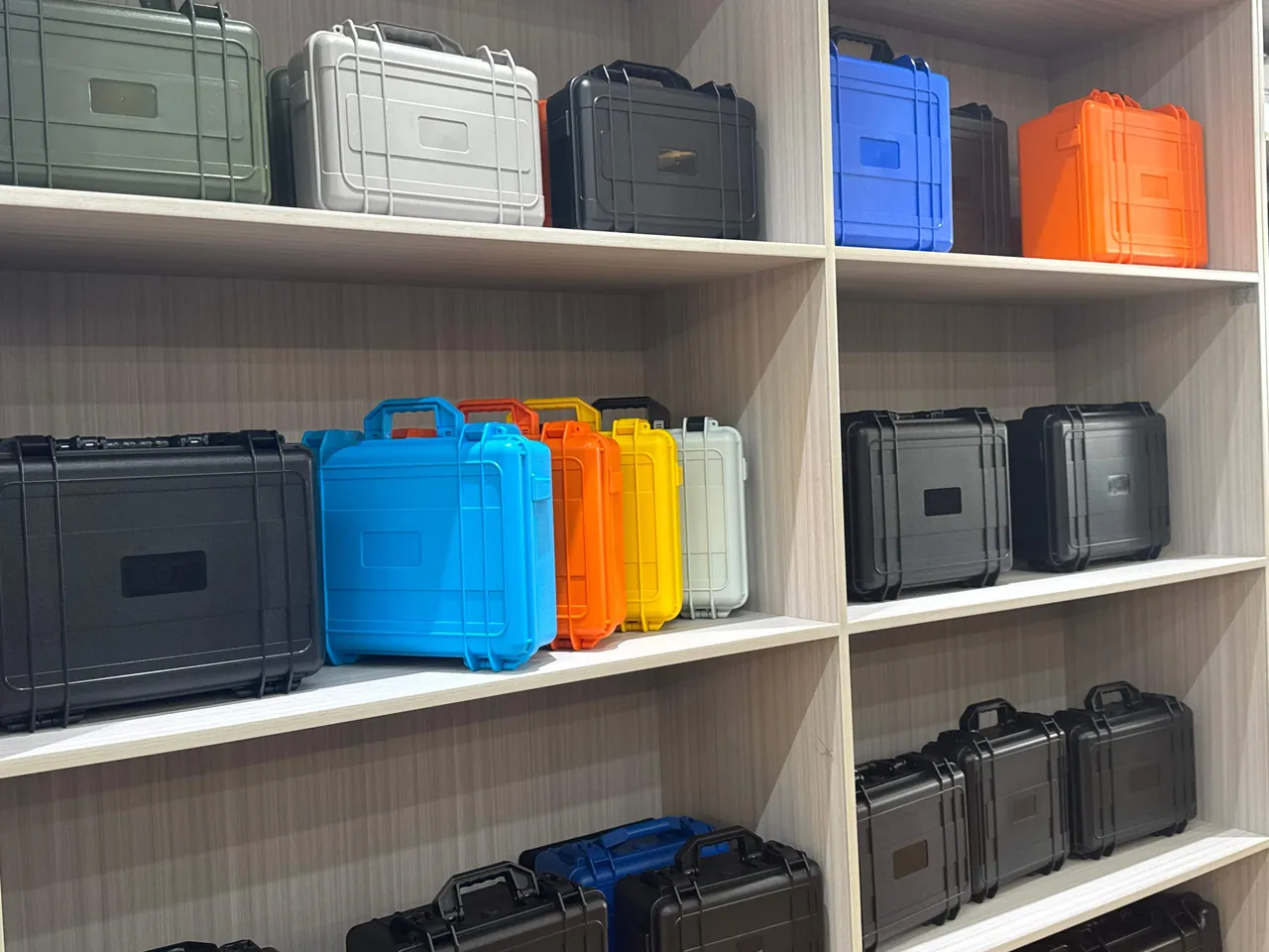
Three test standards provide the basis:
- ISTA series. ISTA 1 for basic integrity, with ISTA 2 and 3 closer to real distribution. See ISTA transport testing procedure and case validation.
- GB/T 4857 series. Chinese basic test methods for transport packages covering vibration, impact, stacking and drop. See GB/T 4857 transport packaging testing for cases.
- MIL-STD-810H. Environmental test methods, of which Method 514 (vibration), 516 (shock), 507 (humidity) and 509 (salt fog) are commonly cited. Note that citing this standard is a reference to environmental test methodology and does not mean the product holds a military certification. See MIL-STD-810H environmental testing and case compliance explained.
Three actionable principles:
- Locate before you cushion. Stop the component moving inside the case first, then absorb energy. A long shaft free to shuffle in thick foam wears and bends through repeated displacement.
- Distribute supports by stiffness. Cradle positions should not be evenly spaced. They should follow the shaft's section changes and weight distribution, with the primary support near the centre of gravity.
- Avoid resonance. Road vibration concentrates at low frequency. If the natural frequency of the case-cradle-shaft system falls inside the excitation band, amplitude is amplified. Adjusting cradle spacing, changing cradle material hardness and offsetting support positions all disperse resonance effectively.
For gearboxes and gear units there is one further requirement: lubricant cleanliness. If a gearbox takes a shock in transit, wear debris already present internally contaminates the lubricant. In circulating lubrication systems, oil cleanliness is commonly controlled against ISO 4406 contamination codes. Transport protection should fix the attitude to prevent oil reaching the breather, avoid severe shock, and include an oil level and oil sample check before handover. Where the customer specifies oil cleanliness, the most robust approach is to drain before transport and refill after delivery.
9. Temperature Control: Post-Sterilisation Cooling, Cold Chain and Low-Temperature Storage
Temperature management for bioprocess components covers two scenarios: cooling and transfer after sterilisation, and low-temperature storage or cold chain transport.
Post-sterilisation cooling and transfer is primarily about avoiding hot-case sealing. If a case is closed while components are still hot, the cooling process creates internal vacuum that draws in outside air and particulate. The correct practice is to wait until components approach ambient temperature before closing, or to use a case fitted with a pressure equalization valve. This matters especially during cleanroom transfer.
Low-temperature and cold chain scenarios require attention to material behaviour:
- Standard PP and ABS lose impact strength at low temperature; transport in cold conditions should use materials with better low-temperature toughness, as discussed in protective cases for extreme temperature environments.
- Gaskets harden in the cold and the risk of compression set rises, so low-temperature flexibility of the seal material must be confirmed.
- Foam inserts become harder and more brittle at low temperature and lose cushioning performance, so thickness must be recalculated against low-temperature dynamic properties.
- Where condensation is possible, include moisture-absorbing material and avoid combining a large temperature step with immediate sealing.
For overall cold chain design, the thermal and monitoring approach described in cold chain food cases and temperature-controlled transport applies equally to bioprocess samples and reagents.
10. Cleaning and Sterilisation: Coordinating with CIP/SIP
The case does not participate in CIP/SIP, but it must work alongside both. Three issues need solving: whether the body can be wiped thoroughly, whether the liner can be replaced or sterilised, and whether the case will carry contamination into the classified area.
Wipe-down compatibility:
- External surfaces non-porous with no deep texture, with radiused transitions of at least 3 mm so a lint-free cloth conforms.
- Gaskets externally seated so the groove can be wiped directly rather than hidden inside.
- Cavity free of blind holes and dead corners, with ribs facing outward.
- A drainage and drying path so water does not collect inside.
- Handles, latches and label recesses shaped so they can be wiped clean without leaving crevices.
Three liner cleaning strategies:
- Wipeable. Closed-cell EVA or PE, cleanable with alcohol, suited to frequent disassembly.
- Replaceable. Layered with a thin consumable contact layer, suited to higher classifications.
- Single use. Clean bag plus disposable tray, suited to sterile transfer and validation batches.
If liner materials must be sterilised with the case, confirm compatibility by route:
| Sterilisation route | Conditions (typical) | Liner compatibility | Notes |
|---|---|---|---|
| --- | --- | --- | --- |
| Steam autoclave | 121 C for 15 to 30 min | EVA and PE tolerate short cycles; deformation needs validation | Repeated cycles accelerate ageing |
| Ethylene oxide | Ambient, requires aeration | Most foams tolerate | Residual EO must be fully aerated |
| Vaporised hydrogen peroxide | Low temperature | Generally good compatibility | Confirm no moisture uptake or distortion |
| Irradiation | Ambient | Some materials cross-link and embrittle | Assess dose versus mechanical property change |
| Dry heat | Above 160 C | Most foams unsuitable | Generally not recommended |
In practice the more common approach is that the liner is not sterilised, only wiped or replaced. Managing the liner as a consumable is more economical and more reliable than expecting it to survive repeated sterilisation. General case cleaning method is covered in how to clean a protective case correctly; only the agent choice has to meet cleanroom requirements.
11. Custom Insert Design: From Parts List to Dedicated Probe Pockets
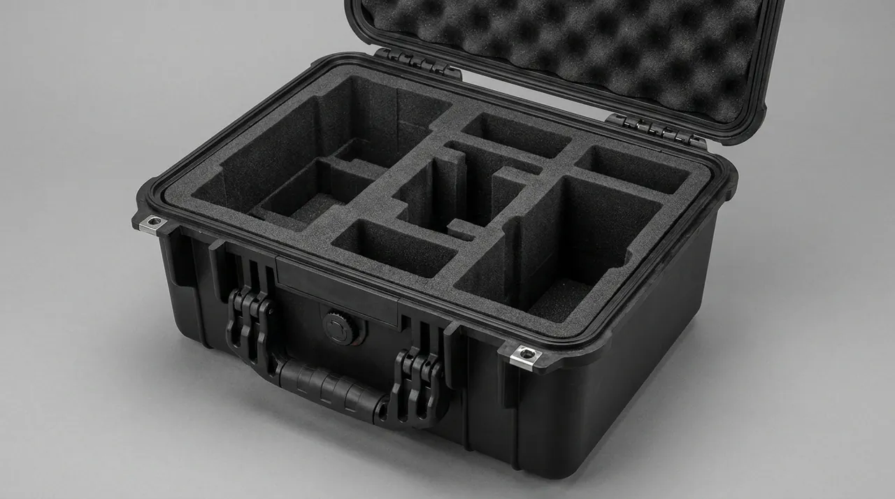
The custom insert is what turns a case into a protection system. The process standardises into six steps.
Step one: parts list and classification. List every component with dimensions, weight, material, precision grade, cleanliness requirement, presence of electronics and whether it is product-contact. Classify as heavy or light, rigid or fragile, wetted or non-wetted.
Step two: layout design. Heavy items low, long items aligned with the case axis, precision items isolated, probes vertical. Leave 10 to 15 percent of height for cushioning and lid compression layers. Probes and fragile items should sit towards the middle of the case rather than at corners, since corners concentrate drop energy.
Step three: forming method.
| Forming method | Process | Advantages | Limitations | Best fit |
|---|---|---|---|---|
| --- | --- | --- | --- | --- |
| CNC routing | CNC milling from solid foam | High precision, complex cavities, economical at low volume | Lower material utilisation | Probe pockets, irregular shapes |
| Die cutting | Blade die cutting plus lamination | Low cost, fast lead time, easily replicated | Limited complex 3D cavities | Regular shapes, large parts |
| Moulded foaming | In-mould foam bonding | Best conformity, low unit cost at volume | Requires tooling; costly to change | High-volume standard cases |
Process comparisons and workflow detail are in EVA foam insert custom process explained and the custom foam insert design guide.
Step four: material selection. Choose density by cushioning requirement, commonly 30 to 90 kg/m3, and material by cleanliness and static requirement. EVA has good closed-cell structure and low shedding and is the mainstream choice. PU foam is soft but sheds readily and should be avoided in clean applications. Where antistatic performance is needed, choose conductive or dissipative material with filler fully encapsulated, as described in ESD shielding case design and application.
Step five: marking and traceability. Laser-mark pocket numbers, component names and specification codes, add an external label area, and include packing list and label card pockets inside. This step directly supports the asset register and expiry management.
Step six: prototype and validation. Fit a 1:1 foam prototype first to confirm clearance and handling feel, then run drop and vibration validation in the loaded condition, opening the case afterwards to inspect probe appearance and cable condition. In custom insert work JUNZHJIA builds from customer 3D data or physical samples and can produce loaded validation sample cases alongside the design.
12. Acceptance, Traceability and Validation Documents
Three acceptance levels:
- Appearance and structure. No deformation, flash or sink marks; smooth hinge operation; continuous unbroken gasket; pockets matching drawing; no sharp edges or burrs, especially for cases carrying single-use components.
- Dimensions and fit. Critical dimensions sampled against drawing; sample fitting to confirm handling force; uniform lid-to-body gap when closed; actual contact condition measured for long shaft cradle points.
- Performance. IP class verification, drop and vibration sampling and seal tightness checks by pressure decay or immersion, as agreed.
AQL sampling is the standard batch disposition method; select inspection level and acceptance quality limit under GB/T 2828.1 or ISO 2859-1. The method is described in custom case acceptance and AQL sampling.
Documents to request:
| Document class | Content | Purpose |
|---|---|---|
| --- | --- | --- |
| Material certificates | Body and liner material reports, RoHS and REACH where required by export market | Cleanliness and compliance review |
| Performance reports | IP class test reports under IEC 60529 / GB/T 4208 | Evidence of sealing capability |
| Transport validation | ISTA or GB/T 4857 test reports | Evidence of protective capability |
| Flammability | UL94 rating where fire requirements apply | Safety review |
| Dimensional records | Inspection records for critical dimensions | Basis for incoming inspection |
| Batch traceability | Case batch number, insert revision, gasket lot | Quality traceability |
Recommended batch record contents: case batch number, insert revision number, gasket lot, date of manufacture, packing list, tamper seal number. In bioprocess use this record can be tied to the asset register and probe calibration records to give case-to-part-to-batch-to-calibration traceability in multiple directions.
13. Purchasing Decisions, Use and Maintenance
Make or buy? Unless the plant has in-house injection moulding and foam conversion, making is usually less economical because tooling amortisation, insert design and validation testing all sit on your books. The sensible boundary is standardised case body plus customised insert, controlling cost while preserving protection. Tooling cost calculation is set out in custom case mould cost analysis.
OEM/ODM cooperation suits bioreactor and fermenter manufacturers. A builder can deliver the case as a standard accessory to the end user, branded to the builder and configured internally to the shipped spare parts and tool list. JUNZHJIA supports this model, including model-specific insert layouts, pocket sets matched to the accessory list, and structural reinforcement and packaging for export. Supplier evaluation criteria are in how to choose a protective case OEM factory.
Use and maintenance:
- Inspect gaskets periodically, every 6 to 12 months, replacing on hardening, cracking or permanent set. See protective case service life and influencing factors.
- Avoid prolonged direct sun exposure; UV accelerates polymer ageing.
- Replace liners on a cycle, setting thresholds by handling or cleaning cycles in high-cleanliness use.
- Manage seals and packing lists. Record the tamper seal number and component list at every use to maintain the traceability chain.
- Store empty cases unloaded, with latches just released to prevent permanent gasket compression.
- Do not mix categories. Classified-area cases and non-classified cases, and wetted-component cases and non-wetted cases, must be marked and never interchanged.
Frequently Asked Questions
Q: Why do bioreactor agitator shafts bend so easily in transit, and how should the insert be designed?
A: A shaft is long and slender, and bending stiffness falls with the cube of the span, so the higher the length-to-diameter ratio, the more vulnerable it is. Bending normally arises in three ways. First, an over-long cantilever: once the shaft end extends past its support, inertia during vibration produces a large bending moment at the end. Second, too few support points: the shaft already sags under self-weight, and superimposed vibration pushes it beyond the elastic limit. Third, the wrong transport attitude: standing vertically, a shaft has a high centre of gravity and topples or takes side impact easily. The insert responds with four measures. First, full-length multi-point support with cradle spacing calculated from stiffness, in practice no more than one third of shaft length, and always including both ends. Second, no cantilever spans: overhang beyond the outermost support stays within two to three shaft diameters, and anything longer gets an auxiliary cradle. Third, a horizontal transport attitude with V-shaped or contoured cradles that conform, restrained by straps rather than rigid clamping. Fourth, soft interleaving or protective sleeves at journals, bearing seats and seal seats so finished mating surfaces never contact a hard cradle. Acceptance can measure straightness and cradle contact condition as incoming inspection items.
Q: What are the most common mistakes when transporting pH and dissolved oxygen probes?
A: The most common mistake is dry transport. A pH glass bulb and its reference junction must stay wet; once dried, the reference electrode drifts irreversibly, which shows up as difficult calibration or insufficient slope. The correct practice is to fit the storage sleeve immediately after removal, fill it with the supplier-specified storage solution and confirm it seals without leaking. The second mistake is laying probes on their side, which leaves the storage solution unevenly distributed and dries the junction locally; store them vertically in individual pockets and prevent tipping. The third is compression stacking: mixing probes with metal or other hard components squeezes fluorescent films and glass membranes into scratches or fractures, so the sensing face must float or rest on a soft bearing. The fourth is coiling cables arbitrarily; long-term small-radius coiling fractures the shield and causes signal drift, so the coiling radius should exceed six to ten times the cable diameter. The fifth is leaving connectors unprotected, when pins bend easily and need caps or foam pads. A pre-transport treatment sheet recording cleaning, storage solution, cap fitting, serial number and last calibration date, mapped to the pocket numbers inside the case, is strongly recommended.
Q: How should single-use bioprocess components be packed, and how does the priority differ from reusable components?
A: The protection objective for single-use components is the integrity of the sterile barrier, not the component. Reusable stainless items fear deformation, scratching and contamination, while single-use items fail through pinholes in outer packaging, micro-cracks at folds or peeled seal edges. Once the barrier fails, the component is unusable even if it looks perfect. Four packing points follow. First, eliminate sharp edges and corners: neither the case interior nor the liner may present any protrusion, screw head or burr able to puncture packaging, and this is the most overlooked and most damaging failure. Second, use a double-bagging logic where the inner layer is the supplier sterile barrier and the outer layer is a protective bag, leaving the case responsible only for mechanical protection and dust and water exclusion. Third, never compress or stack: a folded single-use mixing bag is bulky and pressure-sensitive and should lie flat in one layer or be separated by layer plates. Fourth, control temperature and humidity, keeping heat-sensitive single-use items away from heat sources and watching for internal condensation. Since single-use items also carry expiry dates, the case label area should be a replaceable card for batch and expiry management.
Q: Does a bioprocess component case need IP67, and does a pressure equalization valve compromise sealing?
A: IP65 is sufficient in most scenarios, and IP67 is only needed on specific routes. IP65 means dust tight and protected against water jets from any direction under IEC 60529 and GB/T 4208. For in-plant transfer, covered loading and the spares store to production floor route, IP65 is entirely adequate and easier to handle. IP67, meaning short-term immersion, becomes relevant for cross-zone transport with wet or uncovered loading, transfer routes through washdown areas, movement around cold chain or high-humidity storage, and export sea freight exposed to deck spray or container seepage. Note that choosing IP67 normally requires a pressure equalization valve. Without one, temperature-driven pressure differentials make the lid hard to open and deform the gasket, and the airflow on opening draws external particulate inside. The valve itself does not compromise sealing: it uses a hydrophobic and oleophobic microporous membrane that allows air molecules to pass slowly while blocking liquid water and solid particles, so a case with a correctly installed valve still meets IP65 or even IP67. Choose a valve with a protective shroud, mount it away from direct jetting and liquid pooling, and include the valve exterior in the wipe-down procedure.
Q: Can components be sealed into the case and shipped immediately after sterilisation?
A: Immediate sealing is not recommended; wait until components are close to ambient temperature. The reason is that hot-case sealing creates vacuum. When components are still hot and the case is closed immediately, the internal air contracts as it cools and forms a negative pressure. Two consequences follow. First, the lid becomes hard to open and the gasket is sucked out of shape, losing elasticity over time. Second, if sealing briefly equalises under the differential, outside air is drawn in, carrying particulate from the external surface into the case and directly affecting cleanliness. During cleanroom transfer this matters particularly, because the airflow on opening is one of the main sources of particulate contamination. Three practices are recommended. First, let components cool on the clean side or in the anteroom until close to ambient before closing. Second, if the workflow requires prompt closing, choose a case with a pressure equalization valve so the differential equalises slowly through the membrane. Third, open slowly, releasing the latches to equalise before fully lifting the lid to avoid turbulence. If the liner itself must be sterilised with the case, confirm its distortion and ageing behaviour at sterilisation temperature, since repeated cycles accelerate material degradation.
Q: Is probe calibration affected by transport, and how is it assured?
A: Transport does not change a probe's electrical calibration parameters, but it can cause physical changes that invalidate calibration, so recalibration after transport is required. There are three categories of influence. The first is sensing element damage: a cracked pH glass membrane, a scored DO fluorescent film or lost polarographic electrolyte all push calibration slope well outside factory tolerance. The second is reference junction drying; even when a probe looks perfect, a dried junction causes zero drift, the classic case of looking fine but already drifted. The third is connection change: bent connector pins or a fractured cable shield introduce noise and make readings unstable during calibration. Assurance runs in three stages. Before transport, complete a pre-transport treatment sheet covering cleaning, storage solution, cap fitting, serial number and last calibration date, mapped to pocket numbers inside the case. During transport, control vibration and shock with floating sensing faces, individual pockets and vertical fixing. After transport, recalibrate to the supplier procedure and retain the record. Where the customer permits, calibrate both before and after transport and compare slope difference as quantitative evidence of protection effectiveness.
Q: How should the insert forming method be chosen, and does CNC routing really differ from die cutting?
A: The differences show up in cavity complexity, volume economics and lead time. CNC routing mills cavities from a solid foam block and offers high precision, complex three-dimensional shapes and economical low-volume production, which suits probe pockets and mechanical seal face isolation where fine structure is needed; the trade-off is lower material utilisation and higher unit cost for small parts. Die cutting with lamination stamps flat shapes and stacks them, offering low cost, short lead time, easy replication and high material utilisation; the trade-off is that it handles through-holes and simple steps only, so complex 3D cavities are limited. Moulded foaming bonds foam in a mould, giving the best conformity and the lowest unit cost at volume, but requires tooling and is expensive to change, which suits long-lived standard cases. In practice the most common combination is a laminated die-cut frame plus CNC-routed critical pockets, using die cutting for the main structure and routine pockets and CNC for probes and sealing faces, balancing cost against precision. The choice should follow component precision requirements, batch size and expected revision frequency.
Q: How can you tell whether a case supplier genuinely understands bioprocess applications?
A: Five technical questions will reveal it. First, the aseptic boundary: can they distinguish protecting a component from protecting a sterile barrier, and explain why cases for single-use items must have no sharp edges or burrs? Second, material compatibility: can they describe how body and liner materials behave against isopropanol, hydrogen peroxide and chlorine-based disinfectants, and what steam sterilisation does to foam? Third, probe handling: do they proactively raise storage sleeve fixing, floating sensing faces, cable minimum bend radius and connector protection? Fourth, long-item protection: can they explain cradle distribution principles for agitator shafts, cantilever limits and attitude fixing? Fifth, validation and documentation: can they describe specific test items and pass criteria under ISTA, GB/T 4857 and IEC 60529, and provide material certificates, IP test reports, transport validation reports and batch traceability records? If the discussion covers only size, colour and price, the experience is probably limited to general industrial boxes. In this type of project JUNZHJIA normally starts with component classification and cleanliness grade confirmation, then issues an insert proposal and validation plan, keeping design and validation under one responsible party.
Conclusion & Related Reading
The design logic of a bioreactor and fermentation parts case condenses into one sentence: it protects not just components but the integrity of an entire aseptic boundary. Shafts bend, impellers deform, mechanical seal faces score, and probes bruise and dry out. What these components share is high value, high precision and acute sensitivity to cleanliness and sterility. The case must therefore solve five problems at once: location, cushioning, sealing, cleanability or sterilisability, and traceability.
The implementation path is clear. Set sealing and surface requirements from the cleanliness and biosafety grade. Design a layered insert from the component list, giving probes and seal faces their own dedicated pockets. Validate in the loaded condition against ISTA or GB/T 4857. Then lock quality in with AQL sampling and batch records. It is worth stressing that two cases with the same IP67 rating can differ several-fold in real protection depending on insert design, and two foams of the same density produce very different probe drift rates depending on how the pockets constrain the probe. The difference lives in design and workmanship, not in the certificate. JUNZHJIA supplies protective cases with custom inserts, OEM/ODM programmes and model-specific seal configurations for bioprocess equipment builders, fermentation engineering companies and plant equipment departments, and can support loaded transport validation sample cases alongside the required material and performance documentation. Final configurations are confirmed case by case against the parts list and cleanliness grade.
Related Reading