

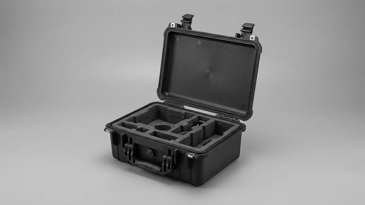
Logging winches split into mechanical and hydraulic types and serve skidding, cableway hauling and loading work. Their drums, brake bands, wire rope, hydraulic valve banks and control modules are loaded and unloaded repeatedly during factory dispatch, forest-to-forest transfer, rental rotation and export sea freight. The conclusion comes first: protection for logging winch parts can be reduced to four lines. The drum must be carried on its journals and a curved cradle so roundness survives. Brake bands must stay clear of oil and of sustained bending so the friction coefficient holds. Wire rope must be coiled to its minimum bending diameter and tied off so kinks and loose strands never start. Control modules and valve banks need moisture and static isolation. Add IP67 sealing and an anti-tangle compartment liner on top of that, and the effects of humid forest air and sea freight corrosion stay contained.
Most winch makers and rental fleets still dispatch parts in timber crates with a tarpaulin, and four defects dominate on arrival. Drums lose roundness during stacking, then spool unevenly and wear their grooves unevenly after refitting. Brake bands take creases, so the arc no longer matches the brake drum and braking force drops or slips. Wire rope coiled loose develops kinks, and a kinked rope cannot be treated as having its original capacity even where no strand is visibly broken. Valve banks and control modules get knocked or damp inside an undivided case and then jam or misbehave. The harder problem is that forest air commonly holds relative humidity above 85 percent, and a wire rope whose zinc coating has been consumed often shows internal corrosion within weeks. The same exposure is covered in the winch parts transport case and the hoist component case articles; here the focus sits on the drum, the brake and the rope, the three structures specific to winches.
Table of Contents
- Logging Winch Component List and Failure Risk Classes
- Drum and Flange Roundness Protection and Support Design
- Brake Bands and Friction Linings: Oil, Moisture and Pressure Marks
- Wire Rope Kinking, Strand Loosening and Coiling Fixation
- Hydraulic Valve Banks and Manifolds: Port Capping and Cleanliness Control
- Control Modules and Sensors: Moisture, Static and Shielding
- Sealing and Ingress Protection: IP67 under IEC 60529 and GB/T 4208
- Humid Forest and Sea Freight Corrosion Control with Salt Spray Verification
- Impact and Restraint Cushion Design: IK Rating and Drop Testing
- Anti-Tangle Liners and Compartment System Design
- Hinges, Latches and Pressure Valves: Hardware Selection
- Transport Validation and Unpacking Acceptance
- Packing Rules and Traceability Marking
- FAQ
- Closing Notes and Further Reading
Logging Winch Component List and Failure Risk Classes
A logging winch, whether a towed skidding winch, a cableway unit or a truck-mounted winch, breaks down for transport into five groups: the drum and journal assembly; the brake system with bands, friction linings and the brake cylinder; wire rope and rigging with thimbles, hooks and sheaves; the hydraulic circuit with pump, valve bank, manifold and lines; and the electrical group with control module, proportional amplifier, sensors and harness. Their sensitivities differ sharply. A drum fears crushing, a brake band fears oil and creasing, wire rope fears kinking and rust, a valve bank fears contamination, and a control module fears damp and static discharge.
Four protection classes make the consequences manageable. The functional class covers control modules, amplifiers and sensors, where damp or a static event can produce erratic operation. The precision class covers spool lands, proportional valve elements and journal fits, where a scratch or contamination changes performance immediately. The structural class covers drums, frames and brake band backing plates, where geometry is the main risk. The consumable class covers wire rope, friction linings and rubber seals, where rust, ageing and internal stress dominate. Once a part is classified, its packing priority, arrival inspection items and spare ratio all follow.
| Component | Typical unit weight | Main failure mechanism | Protection class | Packing points |
|---|---|---|---|---|
| --- | --- | --- | --- | --- |
| Drum and journal assembly | 80 to 400 kg | Loss of roundness, groove damage, journal scoring | Structural | Journal V-blocks plus curved cradle |
| Brake band and lining | 5 to 40 kg | Creasing, oil on friction face, backing plate rust | Structural | Shape-matched cradle plus oil-proof paper |
| Wire rope and rigging | 20 to 300 kg | Kinking, loose strands, internal rust, frayed ends | Consumable | Coiled on a reel with per-coil ties |
| Valve bank and manifold | 15 to 120 kg | Port contamination, spool seizure, seal damage | Precision | Separate cavity plus port plugs |
| Control module and sensor | 1 to 15 kg | Damp, static damage, connector distortion | Functional | Static bag plus desiccant plus soft support |
The weights above are experience ranges and should be replaced by nameplate and packing list data. Where a maker builds several tonnage classes, design a common cradle around drum diameter bands and use interchangeable inserts to absorb small differences, so one case type covers most models without adding new tooling; the modular thinking in the hydraulic lift parts case illustrates the same approach.
Drum and Flange Roundness Protection and Support Design
Winch drums are usually welded thin-wall structures, and their radial stiffness is far lower than their axial stiffness. That single property drives the two transit defects seen most often: an oval cross-section after sustained stacking load, and a local dent where a metal part pressed into the shell. A drum that has gone oval still mounts and turns, but the groove pitch has changed, spooling turns uneven, and the rope and the grooves wear each other faster. This is the classic hidden defect that looks serviceable and is in fact degraded.
Support must follow one rule: journals or flange faces carry the mass, the shell only locates. The common engineering arrangement places the journals in V-blocks at both ends and adds a curved cradle under the shell with a radius 5 to 10 mm larger than the drum and a contact angle between 60 and 90 degrees. A smaller contact angle creates a line contact that dents the shell, while a larger one adds friction during loading. Fit a rigid protective ring around each flange edge, since flanges are the surfaces most often struck by neighbouring metal parts and a deformed flange pushes face runout out of tolerance.
Rope grooves are fine precision features, and a groove floor dented by a hard object rarely returns to its original pitch after repair. Wrap the shell in at least 5 mm of soft protective strip before the outer cover goes on, and never tape directly onto the grooves, because adhesive residue collects dust and oil paste once the drum is back in service. Lifting must use the journals or the flange lifting holes; slinging around the shell pinches it locally and leaves dents that no inspection at the loading yard will catch.
Brake Bands and Friction Linings: Oil, Moisture and Pressure Marks
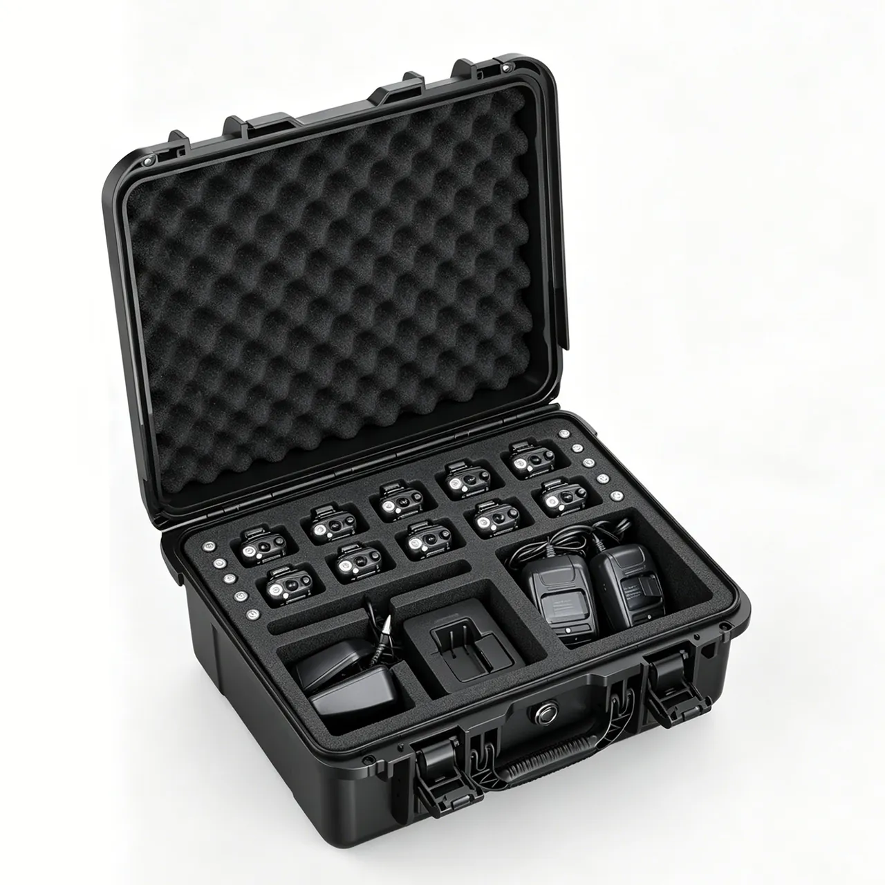
A brake band is normally a steel backing with a friction lining riveted or bonded to it, and it is the most sensitive item in the safety chain of a winch. Three failures can all begin in transit. The backing plate creases and no longer matches the drum arc, so contact area drops and braking becomes uneven. The friction face picks up hydraulic oil or grease, which lowers the coefficient and shows up as slipping under load. The backing plate corrodes in damp air, weakening the riveted or bonded joint.
Preventing creasing means preserving the free shape. A band leaves the factory with a set arc, so it should sit in a shape-matched cradle that supports it evenly from both ends; never coil it, fold it or flatten it under weight. When several bands travel together, put a rigid divider between each layer and locate every band individually, otherwise the upper weight presses straight onto the lining below. Avoid ordinary tape on the lining, because residue contaminates the friction surface; use oil-proof paper and residue-free tied bundling instead.
Oil control depends on physical separation rather than wiping afterwards. Parts that contain oil must occupy a different cavity from brake bands, and this applies above all to hydraulic components with open ports. A minor weep during transit is enough to ruin a whole batch of linings if they share one cavity. Moisture control uses desiccant plus an indicator card to hold internal humidity below roughly 50 percent, with backing plate rust written into the arrival inspection list. As a rule, an oil-contaminated lining should be replaced rather than cleaned on site, because solvent penetrates the lining pores and then bleeds out at working temperature; trace the contamination back to the packing layout instead of accepting repeat failures.
Wire Rope Kinking, Strand Loosening and Coiling Fixation
Wire rope is among the most expensive consumables on a logging winch and among the easiest to destroy through careless packing. Kinking is the most serious outcome: once strands are forced past a sharp bend, the rope should no longer be treated as having its original load capacity even if it looks straight again. Loose strands and the birdcage effect usually begin at a frayed end or where the core has been pinched, and they typically arrive together with internal corrosion.
Coiling diameter is the one packing parameter that cannot be compromised. As an experience rule, the ratio of reel or spool diameter to rope diameter should be at least 20, and 25 to 30 where the rope is handled frequently or stored for long periods. Winding onto a rigid reel or drum core, coil by coil with interlayer pads, is preferred. Where only free coiling is possible, use a figure-eight pattern so the rope's torsional stress cancels out, and never pile it into a heap or press it into shape by foot. Tie the coil every 1 to 1.5 metres with nylon ties or annealed soft wire, and put a soft pad under each tie so the strands are not pinched.
Ends and rigging need separate treatment. Thimbles, rope clips, hooks and sheaves belong in their own compartments rather than next to the rope body, because contact during transit frays the eye splices. Cut ends should receive a heat-shrink sleeve or a dedicated ferrule so strands cannot work loose. Record rope diameter, length and end type on the packing list so the receiving crew can match them to the machine and avoid a refit error.
| Rope diameter d (mm) | Suggested minimum coil diameter (ratio 20 or more) | Coiling method | End treatment |
|---|---|---|---|
| --- | --- | --- | --- |
| 8 to 10 | about 200 mm | Reel or figure-eight | Heat-shrink sleeve plus ferrule |
| 12 to 16 | about 280 to 360 mm | Reel preferred | Eye splice fixed separately |
| 18 to 22 | about 400 to 480 mm | Reel preferred | Thimble plus protective sleeve |
| 24 to 28 | about 520 to 600 mm | Dedicated rigid spool | Swaged end plus sleeve |
Hydraulic Valve Banks and Manifolds: Port Capping and Cleanliness Control
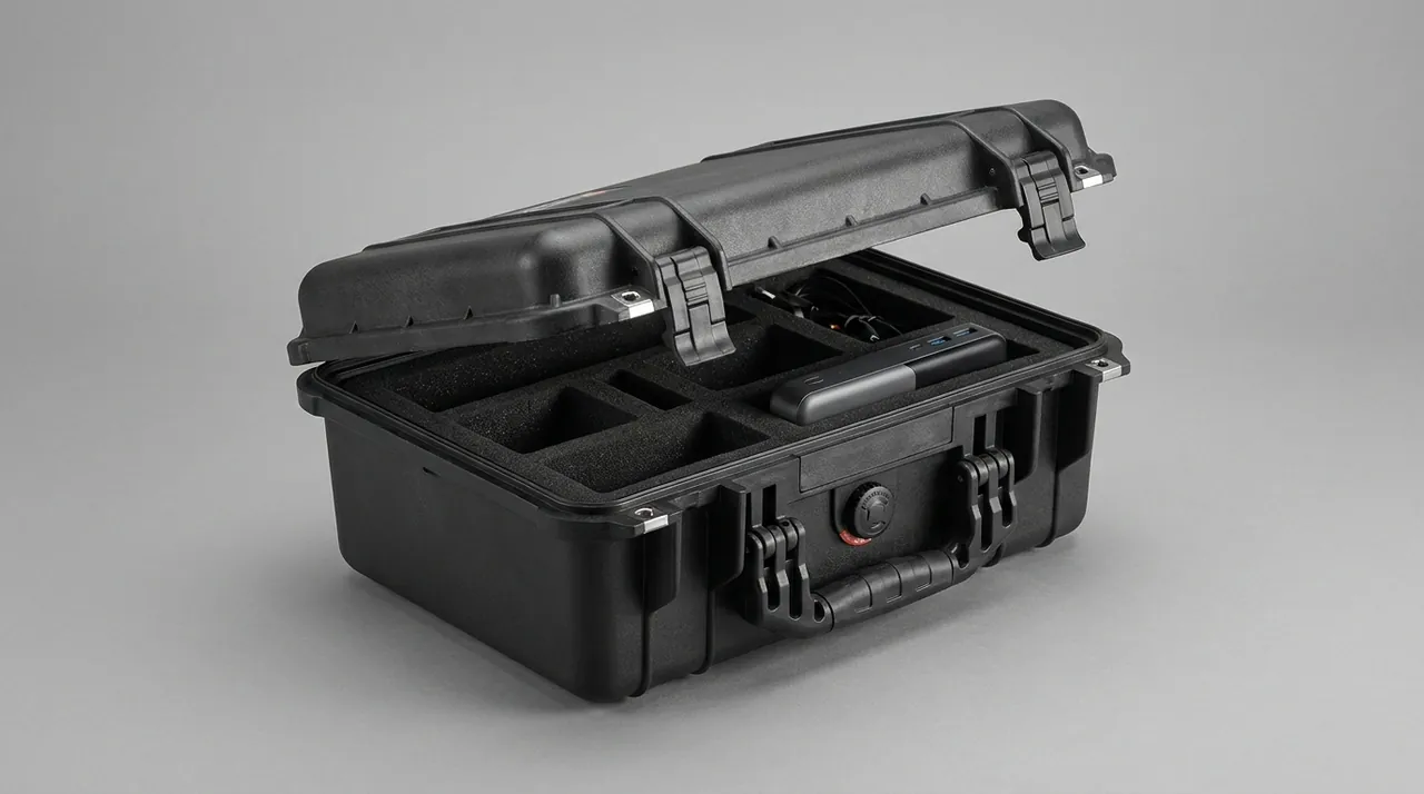
Winch hydraulics usually use a multi-section valve bank and a manifold to control the drum and the brake, and the clearance between spool and body is measured in microns, so any particle that gets inside can cause seizure. ISO 4406 grades fluid cleanliness with the particle counts above 4, 6 and 14 micrometres per millilitre; construction machinery hydraulics commonly target -/18/15, while proportional and servo elements often need -/17/14 or cleaner. Leave a port open in transit and that grade is lost within hours.
Every opening needs a matching closure: metal plugs for threaded ports, cover plates with gaskets for flanged faces, dedicated protectors for cartridge cavities, and skeleton dust caps on hose ends. Never plug a port with rags, newspaper or ordinary tape, because the fibres left behind when the closure is removed do more harm than the open port itself. Manifolds sit in the precision class, so give them a separate cavity and never stack one valve bank on another; line the cavity floor with at least 5 mm of elastic material to absorb road vibration.
Humidity inside the case also affects hydraulics. Spool surfaces and springs form rust spots in damp air, and those spots enter the circuit with the oil and accelerate wear. Place desiccant and an indicator card in the valve cavity, and mark every plug location and size on the packing list so the receiving team can verify them before removal. For rental stock held over long periods, inspect the desiccant each quarter; replacement intervals and case upkeep are described in the protective case service life guide.
Control Modules and Sensors: Moisture, Static and Shielding
Control modules, proportional amplifiers, radio receivers and speed sensors sit in the functional class, and their value is usually far higher than their weight. Damage from damp or from a static discharge frequently only surfaces during machine commissioning. Static protection comes first: seal the module in a static-shielding bag, wrap it in conductive foam or antistatic bubble film, and then place it in the case. The principle matches the ESD shield case approach, except that winch control systems are low-volume and high-variety, so interchangeable liners fit better than fixed pockets.
Moisture control needs two sealing layers. The first is the module's own bag with a small desiccant pack. The second is the case gasket plus the internal drying unit. Fit a humidity indicator card in six steps from 10 to 60 percent so the receiver can judge whether re-drying is needed without opening the liner. On routes with large temperature swings, condensation can form inside the case, and pairing the drying unit with a case pressure equalization valve gives a better result than either measure alone.
Mechanically, modules and sensors need soft, low-rebound support rather than hard stops, because a printed circuit board suffers most from sustained low-level vibration that fatigues solder joints. Keep support compression under about 20 percent, lay the module horizontally so connectors carry no load, and give encoder or speed sensor shafts their own groove with a sleeve, following the practice described in the servo motion controller case article. Where a route crosses very cold or very hot conditions, confirm that liner and gasket materials do not become brittle at low temperature, using the selection logic in the extreme temperature case guide.
Sealing and Ingress Protection: IP67 under IEC 60529 and GB/T 4208
Under IEC 60529 and GB/T 4208, the first digit of the IP code covers solid particles and the second covers water, so IP67 corresponds to dust-tight construction plus no harmful water entry after a short immersion of one metre for thirty minutes. Winch parts need protection from more than rain: forest mud, sap and resin all collect on the sealing face, and dried resin forms a sticky layer that stops the lid pressing the gasket evenly. That is the most common cause of water entry in forest service.
Sealing design concentrates on three points. First, compression: keep the main gasket between 25 and 35 percent, because too little leaks and too much takes a permanent set. Second, continuity: mould the gasket groove in one piece with no corner splices. Third, cleaning discipline: wipe the sealing face and dry it before every pack, and for rope cases that open frequently, fit a cleaning reminder and check sheet on the outside of the lid, in line with the practice set out in the protective case cleaning guide. A double-gasket arrangement also suits frequently opened cases, with the secondary seal handling splash water and the main seal handling air tightness.
Pressure difference is the other overlooked water path. Long sea legs, hot container interiors and forest roads at altitude each create a pressure differential that repeatedly flexes the gasket and makes it breathe briefly. A pressure equalization valve balances the differential while preserving IP67. Note that an IP rating is a laboratory verdict, and real performance depends on assembly quality and maintenance discipline; it is never a licence for prolonged immersion.
Humid Forest and Sea Freight Corrosion Control with Salt Spray Verification
Half of the corrosion problem on winch parts hides where nobody looks. Wire rope is the clearest case: moisture works its way between the strands, internal corrosion begins before any rust is visible on the outside, and by the time surface staining appears the load-bearing cross-section has already been reduced. The zinc coating on galvanised rope is consumed faster under high humidity, thermal cycling and chloride, so a sea freight leg or a coastal warehouse ages the rope noticeably faster than inland storage.
For rope and rigging, combine full wrapping with drying. Wrap the whole reel in VCI film or rust-inhibiting paper, place it in a cavity that holds replaceable desiccant, and keep the reel on a pallet rather than on the floor so ground moisture cannot migrate upward. Make the desiccant a replaceable module so a rental fleet or dealer warehouse can regenerate it during rotation. On export shipments, add an indicator card inside the case as evidence for whether professional drying is needed on arrival.
Structural parts and fasteners follow conventional practice: hot-dip galvanising above 60 micrometres average and powder coating above 80 micrometres, with edges and welds inspected closely, plus insulating pads between stainless fasteners and aluminium to prevent a galvanic couple. Where salt spray performance needs verification, run it as a verification against the neutral salt spray procedure in GB/T 10125, with the exposure length and acceptance level fixed by the project; do not transfer figures from unrelated products to winch components. Repair coating damage found after transit promptly, because a breach corrodes much faster than an intact surface.
Impact and Restraint Cushion Design: IK Rating and Drop Testing
Impact risk for a winch parts case comes from three sources: handling drops, stacking compression and vibration abrasion. Shell impact resistance is described by the IK scale in IEC 62262, where IK08 equals 5 joules and IK10 equals 20 joules; heavy-duty cases are normally specified at IK08 or above with locally thickened corners and edges. Remember that an IK rating characterises the shell, not the protection delivered to the contents, which is entirely a matter of cushioning.
The control parameter in cushioning design is the peak acceleration reaching a part. Taking the usual tolerance of drums, valve banks and electronic modules together, holding that peak in the 30 g to 50 g band is a common industry target, with the exact figure set by the fragility of the item and the maker's requirement. Two means achieve it: sufficient cushioning travel, keeping 15 to 25 mm of wall on all six faces of a part, and centre of gravity control, placing heavy items low and near the geometric centre so that off-centre mass cannot tip the case and cause a second collision.
Drop and vibration validation can follow the drop method in GB/T 4857.5 and the random vibration method in GB/T 4857.23, combined with ISTA or ASTM D4169 for export routes. Where a project calls for MIL-STD-810H method clauses such as Method 516.8 for shock, 514.8 for vibration or 507.6 for humidity, the technical requirement and the report must state that this is a borrowed test method and that the product is non-military-certified, and it must never be described as military qualified; the wording used in the MIL-STD-810H environmental test conformity article applies here. Mark the case with this-side-up and stacking limits, as set out in GB/T 191, because drum assemblies are more orientation-sensitive than ordinary cargo.
Anti-Tangle Liners and Compartment System Design
When wire rope, hooks, thimbles and chain share one case, tangling is the greatest enemy. Tangling costs time on site, and pulling a tangled load apart forces strands against each other, creating fresh kinks and loose strands in the process. Physical separation is the answer: a coiled rope goes into a round or semicircular cavity whose inner diameter is 5 to 10 mm larger than the coil outside diameter; a hook gets a dedicated mount, mouth down, resting on a soft pad; thimbles, clips and sheaves each occupy their own compartment.
Build the compartment system as replaceable components rather than a one-off die cut. For a rental fleet servicing several models, a removable divider liner lets the same case body switch layouts, cutting the number of case types and the storage space they consume; the structure is described in the removable divider liner system article. For materials, use PP honeycomb board or high-density PE foam for round cavities and load dividers so the shape stays stable, and face the surfaces that touch rope with EVA at 45 to 70 Shore A to protect the strands, choosing UL94 V-0 or HB according to the fire requirement of the site.
Cavity floors also need drainage and ventilation thinking. Rope and rigging are often wet from rain when they go back into the case, and a fully closed cavity keeps that moisture inside for months. Fit a removable absorbent mat in the cavity floor and keep a drain plug at the lowest point of the case so water from washing or rain can escape. JUNZHIJIA sizes the rope cavity from the reel outside diameter and the drum diameter first, then works back to the case internal length, which avoids the frequent trap of locking a case body early and forcing the liner to conform to it afterwards. These details look minor, yet they decide whether a wire rope can be stored safely for several months.
Hinges, Latches and Pressure Valves: Hardware Selection
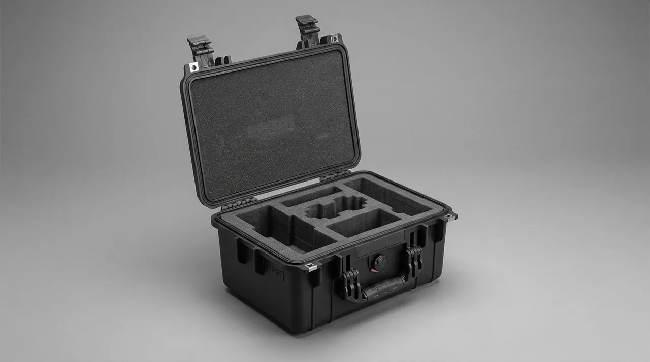
Hardware rarely breaks; it loosens, corrodes or jams, and on a winch parts case each of those translates directly into water entry or a lid that will not open. Specify 304 or 316 stainless hinges with removable pins so a hinge can be swapped in field conditions, and fit at least one hinge per 300 mm of hinge line on a large lid so the middle does not sag and compress the gasket unevenly. Latches should be two-point or multi-point; the longer the case, the more pressing points are needed, and a single latch on a large case will almost certainly let the middle leak.
Gasket and latch are a matched pair: the latch does not exist to hold the lid shut so much as to press the lid onto the gasket with even compression. Buy latches with take-up travel and state the adjustment method in the instructions, because a gasket develops compression set after months of service and the take-up has to be reset. Treat the gasket as a consumable, supply a spare with each case, and match the section to the groove instead of substituting a generic strip. A fuller structural comparison appears in the toolbox hinge, latch and seal selection guide, and where the case needs venting, match the valve's position, airflow and sealing class as described in the case pressure equalization valve article.
Two additional checks belong in purchasing. Verify the material certificate for hardware so that grade 201 stainless is never substituted for 304, and confirm that gaskets and hinges are original matched parts. Look-alike cases with different materials and structures circulate in the market, and the identification methods in the genuine versus fake case guide help rental operators avoid a purchase that costs more over its life than the price difference suggested.
Transport Validation and Unpacking Acceptance
Validation for a winch parts case should cover four risk groups: vibration, impact, stacking and climate. The ISTA series builds a baseline quickly, with 3A for parcel shipment and 3E for unitised and full-load distribution. The GB/T 4857 series supplies individual test methods. ASTM D4169 allows the test sequence to be assembled around a distribution cycle, which suits export routes that combine sea, road and warehousing. Where the product ships overseas, write the port warehouse stage into the test assumptions, because winch parts often sit in a port shed for weeks before collection.
| Test item | Standard basis | Typical conditions | Acceptance points |
|---|---|---|---|
| --- | --- | --- | --- |
| Dust and water | IEC 60529 / GB/T 4208 | Dust class 6 plus immersion class 7 | No dust, no harmful water entry |
| Drop | GB/T 4857.5 | Height graded by package weight | Drum round, valve bank unmoved |
| Random vibration | GB/T 4857.23 | Spectrum and duration by transport mode | No abrasion, loosening or tangling |
| Distribution cycle | ASTM D4169 | Sequence set by chosen grade | Contents function normally |
| Stacking | GB/T 4857 stacking methods | Load by stacking height and top weight | No permanent case distortion |
| Neutral salt spray | GB/T 10125 | Method check, duration by agreement | Coating intact, backing plate rust-free |
| Shock (method borrowed) | MIL-STD-810H Method 516.8 | Non-military-certified, method only | No structural cracking |
| Liner flammability | UL94 | V-0 or HB | Meets the purchase requirement |
| Hydraulic cleanliness | ISO 4406 | Target -/18/15 or cleaner | Ports effectively plugged |
Unpacking acceptance works best as a five-line checklist covering appearance, sealing, hardware, liner and contents. Two items are specific to winches: verify drum roundness with a caliper or dial indicator, and confirm by eye that brake band arcs are correct and friction faces are clean. Volume purchasing can use an AQL approach with tightened rules for key characteristics, as described in the custom case acceptance and AQL sampling article. Keep the inspection records: they are both the evidence for a supplier discussion and the input for the next liner revision.
Packing Rules and Traceability Marking
Nine steps make the packing result repeatable: clean the parts and remove mud, sap and residual oil; inspect and photograph drum grooves, journals and brake band arcs; fit port plugs, connector caps and static-shielding packaging; coil wire rope at a diameter ratio of 20 or more, tie each coil and sleeve the ends; load each part into its model-specific cavity and complete restraint; place the desiccant and humidity card and record the reading; clean the sealing face, close, latch and seal; mark the outside with model, gross weight, centre of gravity, stacking limit and this-side-up; and upload packing photographs, the list and the check sheet to the traceability system with a printed QR label.
For marking and packaging requirements, reference current standards directly: use GB/T 191 for package handling pictorial marks and GB/T 13384 for general technical conditions of mechanical and electrical product packaging, and write case strength, liner fixing, moisture measures and mark content into the documented requirements. That removes most disputes about whether a delivery conforms. On traceability, a QR code linked to packing photographs speeds up site verification, but a paper list should still travel inside the case for forest sites with poor network coverage, and it should state which cavity corresponds to which part number so nobody has to guess after the case is opened. For rental customers servicing several winch models, JUNZHIJIA can supply one shared case body with model-specific inserts, so a single order of cases covers a mixed fleet without new tooling per machine.
FAQ
Q: A logging winch drum is a welded thin-wall part. What usually goes wrong in transit? A: Ovality and local dents are the two common outcomes, and both change the groove pitch, which finally shows up as uneven spooling and uneven groove wear. The root cause is the wrong load path: laying the drum flat and stacking it puts weight straight onto the shell, and a thin-wall structure deforms slowly under sustained pressure. By the time it arrives the deviation may be only a fraction of a millimetre, far too small to catch by eye. Carry the drum on its journals in V-blocks, and add a curved cradle under the shell with a radius slightly larger than the drum and a contact angle between 60 and 90 degrees. At goods-in, check diameter and roundness with a caliper or dial indicator and compare with the pre-shipment record, so any deformation is attributed to the right stage instead of surfacing at assembly. Photograph the groove condition before packing as well, because a groove dent caused by a strap or by a neighbouring part is far easier to attribute with a before-and-after record than with a verbal claim raised months later.
Q: Why should brake bands never be coiled for storage, and how are pressure marks prevented in transit? A: A brake band backing plate is formed to a free arc, so coiling or folding it drives the steel past yield and the arc no longer matches the brake drum. The contact area falls, braking force distributes unevenly, and local overheating and slipping follow in service. The friction lining is equally sensitive to oil, since contamination lowers the coefficient and cannot be reliably restored in the field. In transit, support each band in a shape-matched cradle that carries it evenly from both ends, place a rigid divider between layers when several bands travel together, and locate every band so upper weight never presses onto a lining below. Keep bands in a cavity separate from hydraulic parts and grease. Add desiccant to hold internal humidity under about 50 percent and prevent backing plate corrosion, and put arc check and friction face cleanliness on the arrival inspection list. Record the band arc and lining thickness before shipping too, because a creased band is often rejected on warranty grounds and the pre-ship measurement is the only impartial reference available to either side.
Q: How should wire rope be coiled inside a case to avoid kinks and loose strands? A: Start with the coil diameter. As an experience rule, the reel or spool diameter should be at least 20 times the rope diameter, and 25 to 30 times where the rope is handled often or stored long term, so a 16 mm rope needs roughly a 320 to 480 mm coil. Winding onto a rigid reel or drum core coil by coil, with pads between layers, is the preferred method; where only free coiling is possible, use a figure-eight pattern to cancel torsional stress, and never heap the rope or press it into shape. Tie the coil every 1 to 1.5 metres with soft pads under the ties. Handle ends separately: sleeve or ferrule every cut end, and keep thimbles, clips and hooks in their own compartments so contact damage cannot fray an eye splice. Those two points, the coil diameter and the ends, are where most kinks and loose strands begin. Weighing the finished coil is a useful cross-check, since an unexpected weight usually means a clip, hook or extra length has been left in the same cavity by mistake.
Q: How strict is the cleanliness requirement for hydraulic valve banks, and what keeps it in transit? A: The requirement is strict. ISO 4406 grades fluid cleanliness by particle counts above 4, 6 and 14 micrometres, with common construction machinery targets at -/18/15 and proportional or servo elements usually needing -/17/14. Spool to body clearance is only a few microns, so grit admitted through an open port during transit scores the mating surfaces once the machine runs, causing seizure and, in the worst case, a system shutdown. Cap every opening with the right closure: metal plugs on threaded ports, cover plates with gaskets on flanged faces, protectors in cartridge cavities and skeleton caps on hose ends. Never use rags, newspaper or tape, because loose fibre left behind is worse than the open port. Give manifolds a separate cavity with no stacking, line the cavity with elastic material, and list every plug location and size on the packing list for verification. Where a valve bank carries more than about eight ports, ask for a plug map drawing, because a missing plug on a drain or pilot port is the easiest one to overlook while a truck waits at the loading bay.
Q: Do control modules and sensors need static and moisture protection, and how is it applied? A: Yes, and these two treatments are more often skipped than mechanical protection. A static discharge can damage sensitive devices on a circuit board, and the failure frequently surfaces only at machine commissioning; damp air causes connector oxidation and lower insulation resistance. For static, seal the module in a shielding bag, wrap it in conductive foam or antistatic bubble film before it enters the case, and keep it away from ordinary plastic and foam that generate charge through rubbing. For moisture, use two sealing layers: a small desiccant pack inside the module bag, plus a drying unit and a six-step humidity indicator card inside the case. Mechanically, support the module on low-rebound foam with compression under about 20 percent, lay it horizontally so connectors carry no load, and give encoder or speed sensor shafts a dedicated groove with a sleeve. Keep one spare shielding bag and one desiccant pack under the lid for field replacement, because a module taken out and refitted on site is otherwise returned to the case with no protection at all.
Q: What rust prevention actually works for wire rope and galvanised parts in humid forests? A: The difficulty is that wire rope corrodes from the inside. Moisture migrates between the strands, internal corrosion starts long before any surface rust is visible, and by the time staining appears the load-bearing cross-section has already lost material, so brushing oil onto the outside does little during transport or storage. Combine full wrapping with drying instead: wrap the entire reel in VCI film or rust-inhibiting paper, place it in a cavity with replaceable desiccant, and keep the reel on a pallet so ground moisture cannot rise into it. Galvanised and structural parts follow conventional practice, with hot-dip galvanising above 60 micrometres average and powder coating above 80 micrometres, edges and welds inspected closely, and insulating pads where stainless meets aluminium. Salt spray performance can be checked as a method verification against the neutral salt spray method in GB/T 10125, with duration and grade agreed per project. Galvanised rope whose coating has been consumed by chloride is better replaced than regreased, since fresh grease cannot restore a coating that has already gone from the strand surface.
Q: How is a liner designed to stop tangling, and can one case carry several sets of parts? A: Tangling is solved by physical separation, not by extra strapping. A coiled rope goes into a round or semicircular cavity whose inner diameter exceeds the coil outside diameter by 5 to 10 mm. A hook sits on a dedicated mount, mouth down, on a soft pad. Thimbles, rope clips and sheaves each receive their own compartment. Carrying several sets in one case is practical only when the compartment system can be changed, for example with a removable divider liner that switches layouts in the same case body, using interchangeable inserts to absorb size differences rather than dropping everything into one large cavity. Give cavity floors a removable absorbent mat and keep a drain plug at the lowest point of the case so rain or wash water does not stay inside, because that single detail strongly affects how safely a wire rope can be kept in storage. Label each cavity with its part group as well, so a returning crew puts the rope back into the round cavity instead of the nearest empty space.
Q: Which standards cover transport validation, and how do you avoid buying a poor case in volume? A: Cover all four risk groups. The ISTA series provides 3A for parcel shipment and 3E for unitised and full-load distribution. GB/T 4857.5 supplies the drop method and GB/T 4857.23 the random vibration method. ASTM D4169 assembles a sequence around the distribution cycle. Where MIL-STD-810H method clauses are cited, state that this is method borrowing and that the product is non-military-certified. For acceptance, work at three levels: documents, checking material certificates and design validation reports; appearance, checking edges, sealing face, hardware and liner; and function, using randomly drawn cases for a water spray test, a manual shake check and a liner fit check with the real part. Sampling can follow an AQL approach with sealing, hardware and liner as tightened key characteristics, and confirming that gaskets and hinges are original matched parts usually saves more over the case life than any price negotiation. Ask for the case serial number list before dispatch so that inspection traces to a unit.
Closing Notes and Further Reading
The defects that hide until the machine runs are an oval drum, a changed brake band arc and wire rope rusting inside. Classify by mechanism, set parameters from the real part, then validate and inspect at goods-in.
Further Reading