

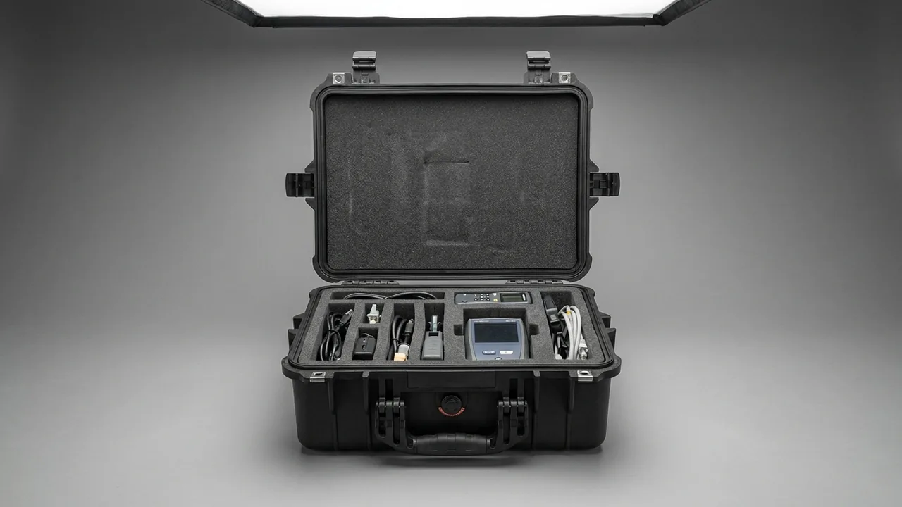
Marine propellers and their shafting components belong to the large, high-value, irreplaceable class of equipment. A fixed-pitch propeller may weigh several hundred kilograms or several tonnes, its blade faces are finished by CNC machining and hand blending, and the fits between shaft sections and bearings are measured in microns. The conclusion JUNZHIJIA puts forward is straightforward: blades, hubs, shaft sections, couplings and bearings must each be protected according to their own stiffness and the nature of their fitted surfaces. Blade faces and leading edges must never be compressed and never scratched, and may touch only soft curved cradles. Hub bores and keyways must be protected to assembly-face tolerance. Heavy off-centre parts need dedicated lifting points and marked centres of gravity that govern the lifting attitude. Dynamic balance surfaces and static balance marks must be photographed before packing and kept clear of all supports. Case hardware must be upgraded in material and isolated against galvanic corrosion in the GB/T 10125 salt fog context. Laying a blade flat on timber baulks, slinging with bare wire rope, and packing bearings loose in the same box with cardboard at the corners are the three most common errors in shipyards and spares stores.
Propeller equipment differs from ordinary machinery because none of its three core values can be repaired after the fact. Hydrodynamic performance comes from the blade section profile and surface roughness, so once a face carries a pressed dimple or a strap mark, welding and fairing will not restore the original section and the cavitation inception point shifts. Assembly performance comes from the interference fit of the tapered bore and keyway, where a single high spot or burr collapses the contact area and forces a re-check of contact pattern and an oil pressure test after fitting. Structural reliability comes from the integrity of the cast bronze or nickel-aluminium-bronze body, and an internal crack created by a drop is invisible to ordinary visual inspection yet can propagate under alternating service loads. Add that propellers are built to a specific vessel, have no shelf substitute, and occupy a drydock window if they need rework, and the return on protecting them in transit is very high. This article sets out liner structures, cushioning parameters, lifting arrangements, corrosion treatments and acceptance clauses by component category, for outfitting departments, owner spares stores, propeller manufacturers and offshore supply chain engineers.
Table of Contents
- Transport Failure Modes and Protection Boundaries for Marine Propeller Parts
- No-Compression, No-Scratch Protection of the Blade Face
- Tolerance Protection of the Hub Bore, Keyway and Assembly Faces
- Support and Restraint for Shaft Sections, Couplings and Bearings
- Protecting Dynamic Balance Surfaces and Static Balance Marks
- Lifting, Centre of Gravity Control and Securing of Heavy Off-Centre Parts
- Salt Fog Corrosion Control: Material Upgrade and Galvanic Isolation
- Oil Sealing and Contamination Control for Controllable Pitch Parts and Hydraulics
- Case Structure, Sealing Grade and Pressure Equalization Valve
- Cushioning Liner Selection and Drop Verification
- Temperature, Humidity, Condensation and Desiccant Configuration
- Transport Compliance Testing and Acceptance on Arrival
- Lifting, Stacking and Marking at the Quay, Shipyard and On Board
- Case Rotation, Cleaning and Propeller Spares Management
- FAQ
- Conclusion and Further Reading
Transport Failure Modes and Protection Boundaries for Marine Propeller Parts
Grouping recent feedback from shipyards and spares stores, propeller equipment transport damage falls into four classes. Compared with small precision parts, the defining difference is that units are heavy, profiles cannot be restored and fitted surfaces cannot be reworked. The first class is profile damage: dimples pressed into the blade face and leading edge by hard objects, grooves cut by sharp items, strap marks left by lashing. It looks minor but is magnified hydrodynamically, because a change in face roughness promotes cavitation and reduces propulsive efficiency. The second class is assembly face damage: high spots knocked into the tapered hub bore, crushing of the working flanks of the keyway, burrs raised on coupling flanges. These defects attack the interference fit and locating accuracy directly, and the only field remedy is hand scraping. The third class is balance and structural damage: local distortion of a dynamic balance surface after impact, loss of static balance weights or marks, and hairline cracking of blade bearing housings in large controllable-pitch hubs after a drop. The fourth class is corrosion and contamination: galvanic attack between bronze blades and stainless shaft sections, blistering and flaking of fastener plating, and breakdown of temporary protective coatings that exposes bare metal.
What these four classes share is that they surface only on arrival and cannot be fixed on site. The protection boundary therefore has to be agreed in writing before packing, not negotiated after damage appears. The table below sets out the failure focus and the corresponding protection action for each core component, and acts as an index to the sections that follow.
| Component | Primary failure mode | Item-level protection | Support and restraint | Process indicator (typical) |
|---|---|---|---|---|
| --- | --- | --- | --- | --- |
| Fixed-pitch blade | Face dimples, leading edge rolling | Soft curved cradle plus face film | Root seated downward, face suspended | No hard contact, point pressure near zero |
| Hub with bore and keyway | Bore high spots, keyway flank crush | Bore sleeve plus keyway strip | Flange face seated, axis vertical | Contact pattern unchanged by transport |
| Shaft and intermediate shaft | Journal scoring, bending | Journal wrap plus full-length soft cradles | Multiple cradles at equal height, no cantilever | Straightness not worse than factory value |
| Coupling flange | Face burrs, bolt hole knocks | Flange face plate plus hole plugs | Face down, axial restraint | Face flatness undamaged |
| Bearing and housing | False brinelling of raceway | Keep original pack and rust film | Inner ring supports, outer ring unloaded | Free rotation, no abnormal noise |
| CPP blade bearing and crank | Housing micro-cracks, link distortion | Separate cavities per item | Located in installation attitude | No visible cracks or plastic deformation |
| Hydraulic cylinder and fittings | Rod scoring, seal face knocks | Rod sleeve plus fitting caps | Rod upright or horizontally supported | Seal faces free of scratches |
No-Compression, No-Scratch Protection of the Blade Face
The blade face and back form the hydrodynamic surface, and the pressure distribution over the section determines lift and cavitation behaviour. There is a single governing rule for profile protection: the face may touch only soft material, and the contact pressure must approach zero. In practice the face first receives a low-tack protective film, then a non-woven or felt sleeve, and is then carried by curved cradles matched to the local surface curvature at the root and mid-span so that the main body of the face hangs free. Cradle material is normally closed-cell EVA or expanded PE, every corner is radiused to R5 or greater, and the surface that touches the blade is faced with felt. Contact area should be as large as geometry allows. Metal brackets, timber baulks and steel tube must never be propped directly against the face, and nylon straps must never be cinched around mid-span, because even a soft-sheathed strap leaves a fine compression pattern under sustained vibration.
The leading and trailing edges are the thinnest part of the blade and the most prone to rolling and chipping, so they should carry removable edge strips or half-round corner protectors whose inner layer is soft and leaves no residue. On three, four and five blade propellers each blade must be separated by its own divider, and blades must never be used to brace one another; if space forces them close together, the only acceptable contact is soft material against soft material. Record the serial number and angular position of every blade during packing, and where blades are interchangeable mark a numbered position on the case so that at the drydock each blade goes straight to its station. The general principles for relieved cavities and radiused corners in profiled liners are described in custom EVA foam insert design, and the approach to soft contact surfaces and suspended support applies equally to blade profiles.
Tolerance Protection of the Hub Bore, Keyway and Assembly Faces
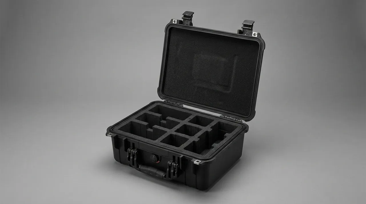
The hub is the junction between blade and shafting, its tapered bore forming an interference fit with the shaft cone while the keyway carries torque. Both surfaces demand zero impact damage. Even a micron-scale high spot on the bore creates local contact with the rest of the taper standing clear, and the contact check then shows an inadequate contact patch, which ultimately affects torque transmission and coaxiality. The bore must therefore receive a tapered sleeve before packing, with a soft inner surface and an outer form that matches the bore closely enough to stop the sleeve shifting; the keyway is filled with a soft strip so that slings or hooks cannot touch the working flanks during lifting.
The preferred packing attitude for a hub is with its axis vertical and the flange face seated downward in a ring cradle, so that the flange face bears evenly. There are two reasons. A bore facing upward cannot trap water or condensation, and the direction of gravity then matches the direction of assembly loads, so transport cannot press a skewed witness mark into the flange face. Where a hub is too large and must lie horizontally, place V-shaped cradles of equal height under the outside diameter and add axial stops on both sides to prevent rolling. Every stud hole and dowel hole should be plugged, using soft PE plugs, and the holes should be blown clean before plugging, because swarf left inside a hole becomes an abrasive under vibration.
At acceptance, check the bore contact pattern with red lead or blue oil after cleaning, sampling at least one location on site, and check the keyway flanks for high spots with a straight edge and feeler gauge. The acceptance clause should read that the bore and keyway contact check result is unchanged by transport, rather than the much weaker statement that the appearance is free of damage.
Support and Restraint for Shaft Sections, Couplings and Bearings
Propeller shafts, intermediate shafts and stern tubes are often longer than the diagonal of the case, and the dominant risk is not impact but bending. A slender shaft deflects under its own weight and under vibration, and if the cradle spacing is too wide or the cradle heights are uneven, the deflection exceeds allowance and the machined journals take a permanent set. The established practice is multiple cradles, at equal height, with soft tops. Space the cradles at roughly 30 to 40 times the shaft diameter, taking the lower end of that range for slender shafts as a rule of thumb, hold the height difference between all cradle tops within 1 mm, and use half-round soft cradles to spread the load and avoid line contact scoring the journal. Journals and keyways should receive an additional soft wrap so nothing outside the cradles can mark them.
Single-end cantilever support and sling-carry transport are never acceptable. The first develops the maximum bending moment from self weight alone, and the second leaves a circumferential compression mark at each sling contact, and may cause local plastic deformation. Shaft sections also need axial restraint inside the case, so that braking inertia cannot slide them into the case wall; place the stops against non-fitted features such as a shaft shoulder, never against a journal or taper.
Bearings follow the opposite logic to shafts: their enemy is not bending but false brinelling. When a stationary bearing is exposed to vibration, the rolling elements micro-slide against the raceway, the lubricant film breaks down locally, cold welding and tearing occur, and evenly spaced indentations appear at the rolling element pitch. Depth is typically only microns, so neither eye nor fingertip detects it, yet after installation the bearing emits periodic noise at speed and spalls within a short period. Keep bearings in their original packaging with the factory rust preventive film intact, do not let the outer ring carry radial load in transit, and let a housed bearing sit on its housing base with the inner ring unloaded. Where bearings travel in the same case as shafts, a divider must separate them so that bearing outside diameters and journals cannot press against each other. The vibration control discussed here addresses a different objective from hydraulic cleanliness; density and compression figures for cushioning materials are compared in cushioning liner selection.
Protecting Dynamic Balance Surfaces and Static Balance Marks
Propellers are statically balanced before dispatch, and dynamically balanced where required, and the balance is recorded through marks: balance weights, blending recesses at the blade root, or simply a scribed line and characters. These marks are part of the manufacturing record. If they are lost or altered in transit, the whole propeller must be re-balanced, and balancing a large propeller needs dedicated tooling and a long lead time. Two requirements follow. The marks themselves must not be abraded, covered or substituted, and the geometry of the balance region must not be altered by impact, including the tightness of balance weights.
The practical routine is as follows. Photograph every balance mark, weight position and root blending area before packing, and place a printed record in the case. Coat weight bolts with anti-seize compound and paint a torque witness line, so that movement can be judged by comparing the line before and after transport. Keep the balance region relieved inside the cavity, and never let a cradle bear on a weight or a blending area. Because residual unbalance is set by the actual mass distribution of the blades, the packing position and serial number of each blade must match the factory record; blades must not be swapped around merely to suit cavity dimensions. On arrival, verify that the balance marks are intact and that the witness lines have not shifted. If a line has moved, re-torque and re-verify the balance state before the propeller proceeds to assembly.
On controllable-pitch propellers the blade installation angle about the blade root axis is set by the crank mechanism, and any angular displacement of the blade root flange relative to the hub during transport can produce an angle error on reassembly. Blades and hub should therefore travel in separate cases or separate compartments, each independently restrained. Never place an assembled blade on the hub and rely on its own weight to hold it.
Lifting, Centre of Gravity Control and Securing of Heavy Off-Centre Parts
Lifting hubs, impeller-type heavy parts and complete propellers is the highest-risk step in the whole transport chain, and the cause is usually not insufficient crane capacity but a misjudged centre of gravity and a poorly chosen lifting point. An off-centre item swings and rotates the moment it leaves the ground. If the lifting point is not in the same vertical plane as the centre of gravity, the sling load rises well above the design value and the item rotates hard into whatever is nearby. Four rules apply. Lifting points must match the manufacturer's marked points, with no improvised attachment to stiffeners or stud holes. The centre of gravity must be established before the lift and marked on both the item and the case. Sheathed slings must be used with a sling angle held within 60 degrees, because a wider included angle multiplies the sling load. No one may enter the space beneath a suspended item or between the item and the case.
Large propellers are normally loaded by bringing the case into position and lowering the item, not by lifting the case above the item. Control swing with a tag line, slow the descent at roughly 100 mm above the cavity, and have one operator guide alignment from the side, with hands kept out of the gap between item and cavity. Once seated, confirm that all cradles carry load evenly before releasing the sling. Where the case itself must be lifted again, for loading or for lowering into a hold, use the case lifting points and re-verify the internal restraint first, because a locating block that was sound may shift once the case tilts.
Besides locating blocks, off-centre items need a set of axial stops bearing on stiff body features through soft pads. Where the centre of gravity sits clearly to one side, add ballast or a thicker cushion layer on the light side so that the combined centre of gravity approaches the geometric centre of the case. This improves the lifting attitude and reduces eccentric load during stacking. Modular approaches to dividing a case and providing changeable locating features are described in removable divider and locating systems.
Salt Fog Corrosion Control: Material Upgrade and Galvanic Isolation
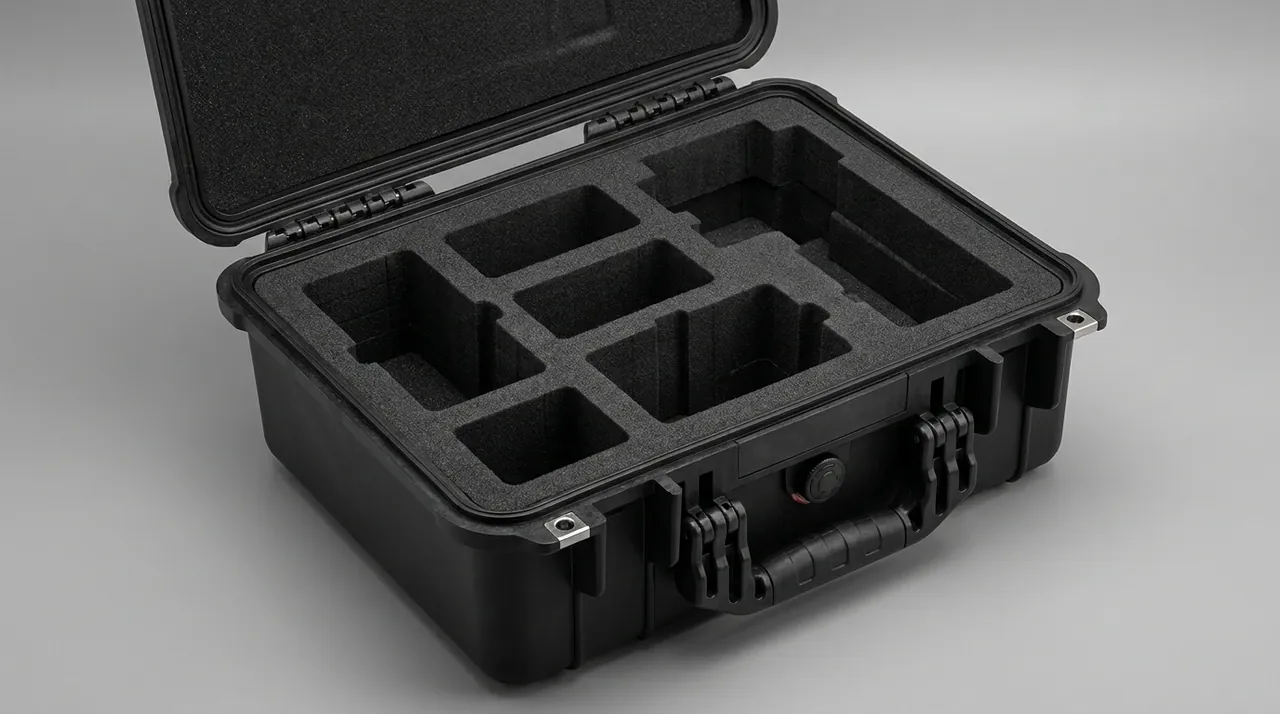
The corrosion environment for marine equipment is not merely damp. It is salt fog, sustained high humidity, a day-night temperature cycle and galvanic coupling acting together. Propeller parts are the classic mixed-metal load: bronze blades, stainless shaft sections, carbon steel fasteners and aluminium frame components, with potential differences large enough in marine air to drive galvanic attack. Protection works on three levels. For material, expose only 316 or 316L stainless steel hardware, specify hard anodising for aluminium parts, and use A4-70 or better for fasteners. For structure, fit nylon or PTFE washers between dissimilar metal contact surfaces to break the current path, and coat bolted joints with anti-seize compound so threads do not seize during long storage. For verification, run a neutral salt fog test to GB/T 10125, in which case hardware, latches and hinges show no functional corrosion within 96 hours.
Coating and storage are part of the same discipline. A peelable temporary coating may be applied to blade faces before packing and stripped as a single layer before installation, avoiding solvent residue on the surface. Carbon steel parts and machined faces receive rust preventive oil of a type that ordinary cleaning agents can remove, so that later coating operations are not contaminated. In storage, never let a case sit directly on a wet steel deck or concrete floor; raise it on dunnage and keep air moving around it. At a quay, avoid parking cases hard against the ship's side, because that is where spray concentrates. Latches and hinges accumulate salt more stubbornly than any other feature; their general construction and corrosion detailing are covered in hinge, latch and seal construction, but a marine application should step the whole material specification up one grade.
A simple and effective field check is to look for white or green salt crystals in the gaps around latches and hinges. Their presence means washing and drying have been inadequate, and the hardware should be dismantled and inspected immediately, even if the outside looks sound. After every return from a voyage, rinse the case free of salt and dry it, paying particular attention to the seal groove, latches, hinges and the area around the pressure equalization valve.
Oil Sealing and Contamination Control for Controllable Pitch Parts and Hydraulics
Controllable-pitch parts include blade bearings, the crank disc, sliding blocks, the servo cylinder and pipe fittings. They share three characteristics: high machining accuracy, tight oil cleanliness limits and seals that must not be allowed to dry out. The piston rod of a servo cylinder carries a very thin plated layer and is the most easily damaged feature of the whole mechanism, so it travels fully sleeved, positioned either upright or horizontally supported, and must never be used as a load-bearing support point. Pipe fittings and ports normally ship with plastic plugs; keep those plugs and add secondary caps during packing, so that if a plug is knocked out, grit cannot enter the oil circuit.
Hydraulic components are extremely sensitive to particulate contamination, cleanliness normally being classified to ISO 4406. Transport does not involve flushing, so the objective is simply to introduce no new contamination. Do not use crumb-shedding cardboard or linting cloth as the direct contact material for hydraulic items, clear swarf from liner cuts, and never mix machined metal parts in the same case as abrasives, tools or anything else that generates debris. If hydraulic items must share a case with blades, which is not recommended, they belong in a separate sealed inner compartment.
Rubber seals such as O-rings, lip seals and glyd rings carry their own storage requirements: they dislike heat, light and compression set, so they belong flat in a light-excluding bag, never folded or hung on a hook, at a typical 15 to 25 degrees Celsius away from heat sources and ultraviolet. Seal material and compression directly govern sealing performance after assembly, and the trade-offs are set out in seal material selection. On arrival, sample seals for hardening, crazing and permanent deformation, and check the shelf life.
Case Structure, Sealing Grade and Pressure Equalization Valve
Case selection for propeller parts must satisfy three requirements at once: load carrying, sealing and portability. On load carrying, the load path from the base must transmit the weight of heavy items directly into the case corners or steel feet; a foam layer must never become a structural load path. For hub cases weighing several tonnes, provide steel or reinforced plastic load beams inside the case, with foam carrying only cushioning and location duties. On sealing, sea freight and open quay storage require at least IP65 to IEC 60529 and GB/T 4208, upgraded to IP67 where deck washdown or lighterage applies. Seals should be silicone or EPDM, compressed 25 to 35 percent at 50 to 60 Shore A, and must be resistant to seawater and ultraviolet.
On portability, provide four or more compliant lifting points positioned on the structural load path and clearly identified on the outside of the case with colour or graphics, plus forklift pockets or a pallet base. Heavy cases should not rely on castors for movement; castors suit empty cases or light loads over short distances, while a loaded case belongs on a forklift, overhead crane or flatbed, with metal corner reinforcement added where needed.
A pressure equalization valve matters especially on a propeller case because the temperature range during handling is wide and the enclosed volume is large. A case that cannot breathe develops noticeable internal pressure in the heat, so opening demands much greater force and the seal can behave as if stuck. Three selection points: use a waterproof breathable membrane so that washdown water and rain cannot enter; size the airflow from case volume and temperature differential, typically 200 to 500 mL/min; and mount the valve high on a side wall, clear of lifting load paths and direct water streams. Membrane options and mounting details are compared in pressure equalization valve selection. Note that fitting a valve does not remove the need for desiccant, because a valve equalises pressure but does not block vapour exchange.
| Protection grade | Reference standard | Typical test condition | Applicable transit and storage | Points to consider |
|---|---|---|---|---|
| --- | --- | --- | --- | --- |
| IP65 | IEC 60529 / GB/T 4208 | Water jets, no harmful effect | Sheet-sided vehicles, indoor yard moves | Unsuitable for open deck storage |
| IP66 | IEC 60529 / GB/T 4208 | Powerful water jets | Loading in rain, brief open air | Seals must resist UV and ozone |
| IP67 | IEC 60529 / GB/T 4208 | 1 m depth for 30 minutes | Lighterage, deck water, spray | Breathable waterproof valve required |
| IP68 | IEC 60529 / GB/T 4208 | Continuous immersion, condition agreed | Boat transfer, realistic overboard risk | Dead weight and lifting must be recalculated |
| Added corrosion | GB/T 10125 | Neutral salt fog, 96 hours or more | Coastal and on-board long storage | Passivation and galvanic isolation |
Cushioning Liner Selection and Drop Verification
The objective of cushioning is not softness but control of peak acceleration combined with distribution of impact energy over a sufficient contact area. Closed-cell EVA or PE foam at 40 to 70 kg/m3 is the usual first stage, compressed 12 to 20 percent. For items over 500 kg, foam should serve only as a locating and levelling layer, with the energy absorbed by separate elastic support blocks or a composite layer arrangement that forms a two-stage isolation and dissipates energy progressively. Hardness and rebound govern long-term compression set, so ask for compression set test data rather than accepting a density figure alone.
Drop and impact verification heights are normally banded by gross item weight. As a rule of thumb, items under 50 kg are checked from 80 cm, 50 to 200 kg from 60 cm, 200 to 1000 kg from 40 cm, and items above 1000 kg from 25 to 30 cm. These are engineering approximations that should always be confirmed by test. The purpose is to prove that the liner does not collapse through, that locating blocks do not detach, and that a heavy item never contacts the case wall directly. Thin-walled curved parts such as blades need a separate local pressure check, because a small contact area can exceed the yield limit even when the whole-case acceleration stays within allowance. The remedy is a larger foam pad between cradle and blade face, spreading a concentrated load over more area.
Design the test sequence around the relevant projects in ISTA transport testing procedures or ASTM D4169 distribution cycle testing, combined with GB/T 4857 transport packaging testing for stacking, vibration and drop. Before freezing the liner design, run a loading trial with a weighted mock-up to confirm repeatable handling and reliable restraint. Where a spares case must accept several blade patterns, make the cradles replaceable components so the case body itself does not change; the economics of that trade-off are discussed in insert and mould cost analysis.
Temperature, Humidity, Condensation and Desiccant Configuration
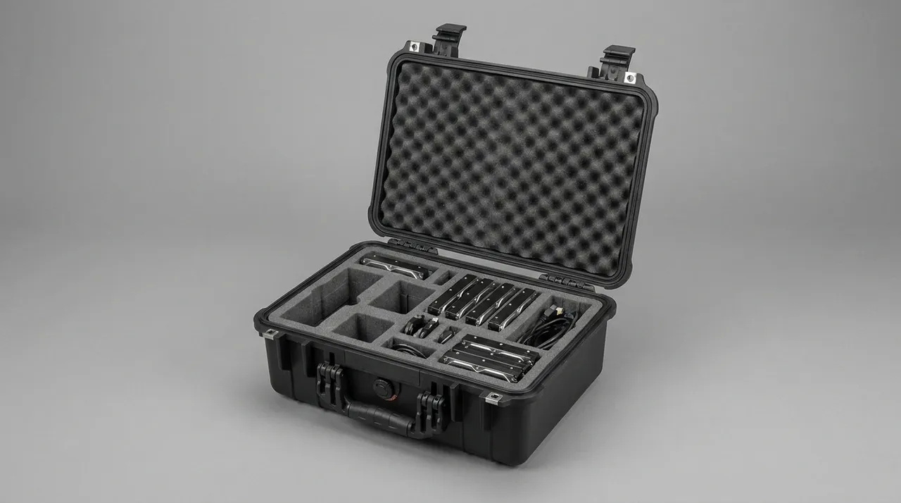
Condensation is far more aggressive at sea than on land. A container bakes on deck by day and cools rapidly at night, so moisture condenses repeatedly on metal surfaces. Bronze and stainless steel are both prone to pitting and crevice corrosion in this wet-dry cycling, and plated fasteners blister. The control sequence has four steps: seal, desiccant, humidity indication, and warming before opening. Desiccant is typically dosed at 80 to 120 g/m3, taking the upper end for long voyages or where the route calls at humid ports. Avoid calcium chloride types, because they can release liquid after absorbing moisture, and a salt solution running onto a blade face or journal is a corrosion source of your own making. Silica gel and montmorillonite are safer choices.
Mount the humidity indicator card where it is visible as soon as the case is opened, and keep a record sheet in the case so that every reading is logged. That log turns the question of whether the case has ever admitted water into traceable evidence. Do not open the case immediately on arrival; let it stand in the store for 2 to 4 hours to warm up, so that condensate does not form directly on machined tapers and journals. Where rubber seals are inside the case, do not drive humidity to zero, since rubber that loses moisture hardens and crazes; 30 to 50 percent relative humidity is the safer band.
For spares cases that sit on deck for long periods, fit a replaceable desiccant module with a viewing window on the outside of the case, so maintenance staff can judge desiccant condition without opening it. Reducing the number of openings is one of the most effective ways to limit moisture ingress. General cleaning and care routines are described in protective case cleaning and maintenance.
Transport Compliance Testing and Acceptance on Arrival
Verification should run on two tracks, case level and component level. Case-level testing treats the packed case as a distribution package, using the GB/T 4857 series for stacking, random vibration, drop and impact, confirming that the body, latches, seals and liner survive the limit loads, with salt fog verified to GB/T 10125. Environmental methods may be drawn from MIL-STD-810H, which serves only as a methodology reference for environmental test methods and does not imply any military certification. Component-level verification happens before the liner is frozen, using weighted mock-ups to check restraint reliability and foam compression set. For cases containing hydraulic items, add a post-vibration check that port plugs and caps are still in place.
The most important point at acceptance is to write measurable items into the clause rather than a blanket statement that there is no damage. Acceptance of propeller parts is best handled in four steps. First an appearance and cleanliness inspection focused on blade faces, leading edges, bores, keyways and journals. Second a geometry check sampling shaft straightness, flange face flatness and bore contact pattern. Third a function check of bearing rotation freedom and hydraulic port plugging. Fourth a status comparison against the balance mark photographs, the torque witness lines and the packing list serials. Any anomaly must be recorded and photographed before the item goes into store, because damage found in the store and damage found on the road lead to entirely different liability conclusions.
| Test item | Reference standard | Suggested condition (typical) | Judgement criteria |
|---|---|---|---|
| --- | --- | --- | --- |
| Stacking | GB/T 4857.3 | Load converted from stack height, 24 hours | No permanent case distortion, beams unbent |
| Random vibration | GB/T 4857.23 / ASTM D4169 | One road spectrum and one sea spectrum | Locating blocks tight, shaft cradles unmoved |
| Drop and impact | GB/T 4857.5 / ISTA 2A | Corner, edge and face once each, height by weight | No liner collapse through, no hard contact mark |
| Salt fog | GB/T 10125 | Neutral salt fog, 96 hours | No pitting, no galvanic corrosion |
| Damp heat cycling | MIL-STD-810H method 507 | High temperature, high humidity cycling | No standing condensate, no rust staining on journals |
| Sealing under immersion | IEC 60529 / GB/T 4208 | IP67 short immersion, or agreed IP68 condition | No water traces inside, indicator unchanged |
Lifting, Stacking and Marking at the Quay, Shipyard and On Board
The route from works to drydock normally crosses road, storage yard, barge and ship's hold, and every transfer is a lifting operation. Inspect the restraint before dispatch: fill all cavity clearances with soft foam, re-check strap tension, and secure every removable item, including caps, edge strips, locating blocks and tool bags, individually. The decisive difference between sea and road transport is six degrees of freedom. Roll and pitch make any inadequately restrained item oscillate inside the case, and although the amplitude is small, the accumulated effect over several days can cause wear. Clearances for a seagoing case should therefore be tighter than for road-only use.
Position the case away from the shell plating where spray lands and away from hatch areas, raise it on dunnage so standing water cannot soak the base, and keep it clear of the load path of mooring lines and securing chains. On deck, lash the case to the ship's structure, and attach lashings to reinforced parts of the case rather than to latches or handles. Use sheathed slings and hold the sling angle within 60 degrees; at sea, add tag lines to control swing. Nobody may work under a suspended case or in the gap between case and ship structure.
Marking follows GB/T 191 and GB/T 13384, and should include at least this way up, keep dry, centre of gravity, lifting points, do not roll, plus case number, part number, net weight, gross weight and external dimensions. Cases containing blades should additionally carry a no-compression notice for the blade face and a blade orientation note; cases containing precision shaft sections should be marked against bending; off-centre heavy cases should show the centre of gravity graphically on both sides together with the number of lifting points. Bilingual or graphical marking helps where different stevedore gangs handle the case. Castered cases must have the wheels locked and anti-slip pads fitted on board, so that vessel motion cannot shift them.
Case Rotation, Cleaning and Propeller Spares Management
Propeller spares cases often serve aboard a vessel for years, and how well they are cleaned on return determines protection on the next voyage. Fix the return routine: read and log the humidity indicator immediately on opening; inspect the item for contamination on blade faces, bores, journals and flanges; rinse salt off the case with fresh water and dry it, concentrating on the seal groove, latches, hinges and valve surround; check seals for hardening, cracking and permanent compression set; check hinge tightness and latch spring force; confirm there is no residual oil contamination inside, then dry and close. Cases in frequent rotation should have a sealing spot check and liner compression set check each year. Economic service life is commonly estimated at 5 to 8 years, but a condition-based decision is more reliable, and the method is set out in protective case service life assessment.
One easily overlooked issue in spares management is that several blade and shaft sets for the same vessel class look almost identical and are easily mixed. Case, liner number and spares ledger must correspond one to one, with a fade-resistant label on the outside giving vessel, propeller type and part number, and a packing list plus liner numbering drawing inside. For spares held in long-term preservation, open and re-inspect the rust preventive film and desiccant consumption every 12 months.
For shipyards, owners and propeller manufacturers, JUNZHIJIA supplies a package that runs from liner design through to delivery documentation. From the customer's 3D model or site measurements, JUNZHIJIA designs blade curved cradles and leading edge strips, hub ring cradles and bore sleeves, multi-cradle equal-height shaft supports with anti-slide axial restraint, coupling flange plates, separate bearing compartments and centre-of-gravity balancing features for off-centre heavy items, using seawater-resistant, ESD or low-outgassing formulations as required. Case bodies are offered in modified PP, ABS and rotationally moulded LLDPE with 316 stainless steel hardware, seawater-resistant seals, waterproof breathable equalization valves and heavy-duty reinforced corners, with lifting points sized from the loaded centre of gravity and marked externally. Documentation can include liner drawings and material lists, sealing grade and compression statements, transport test reports to GB/T 4857, ISTA or ASTM D4169, GB/T 10125 salt fog summaries, packing lists and arrival acceptance forms. OEM and ODM branding are supported, and a fleet with several propeller types can be served by a platform approach pairing standard case bodies with changeable cradle sets.
FAQ
Q: Can a blade face simply be wrapped in soft cloth or foam sheet and then laid on timber baulks?
A: Wrapping is fine, but timber baulks must not be the support. Soft cloth and foam sheet prevent minor abrasion and dust, and they are a legitimate first layer, yet they do nothing about the underlying problem that the support is hard and geometrically mismatched. A timber baulk touches a curved face along a line or at a point, so contact pressure is very high, and road vibration presses a compression pattern into the face that corresponds to the baulk edge. Repainting does not remove that pattern. The correct stack-up is a low-tack film on the face, a non-woven or felt sleeve over it, and curved cradles matched to the local curvature carrying the root and mid-span, with felt facing the blade and all corners radiused to R5 or greater, so that the main body of the face hangs clear. Wrapping material also matters. Avoid crumb-shedding cardboard and plasticised PVC foam, because the first creates particulate contamination while the second can release plasticiser as temperature rises, leaving an oil film that harms later coating adhesion. For blades in long-term preservation, open the case every 12 months to confirm the film and cradles have neither shifted nor bonded to the surface.
Q: Can propeller blades and the hub travel in the same case?
A: Technically yes, provided they are in separate compartments and never in contact, but separate cases are usually preferable. The hub is a rigid casting with many sharp edges, while a blade is a thin-walled curved part with low local stiffness, so the risk in sharing a case is the stiffness mismatch. Impact energy transmits from hub to blade, and the blade then carries a local load far above its design value. Where shipping economics force a shared case, fit a divider that splits the interior into two compartments, secure the hub in the lower compartment seated on its flange face, restrain the blades independently in the upper compartment, and make the divider stiff enough to resist hub displacement under impact. Leave at least 20 mm between divider and blades and fill that gap with soft foam. Watch the centre of gravity as well, because the hub usually outweighs any single blade considerably and should sit near the geometric centre of the case so that lifting is not eccentric. Where blades and hub are matched pairs with pairing marks, keep the pairing intact inside one case and include the pairing list.
Q: Is there a general rule of thumb for shaft cradle spacing?
A: There is a working range, but the stiffness calculation governs. Common practice is to space cradles at 30 to 40 times the shaft diameter, taking the lower end for slender or stainless shafts and the upper end for short stiff sections. The purpose of that range is not strength, since static strength margin is usually large, but control of self-weight and vibration deflection within machining tolerance. A more rigorous approach models the shaft as a simply supported beam, calculates self-weight deflection, and chooses a span at which maximum deflection stays within one third of the total straightness tolerance. Three conditions matter as much as spacing. First, the height difference between cradle tops should stay within 1 mm, because uneven heights effectively enlarge the span. Second, cradle contact should be a half-round soft surface, avoiding line contact that scores the journal. Third, neither single-end cantilever support nor sling carry is acceptable, since the first creates the maximum bending moment and the second leaves a circumferential compression mark. On arrival, sample straightness along the full length and compare it with the factory value; that check reveals more about transport quality than any visual inspection.
Q: Why do bearings suffer damage in transit that looks harmless but produces noise after installation?
A: This is classic false brinelling, a form of fretting wear driven by vibration. A stationary bearing under sustained vibration experiences repeated micro-sliding at the rolling element contacts, the lubricant film breaks down locally, and the metal surfaces cold weld and tear, producing indentations spaced at the rolling element pitch. Depth is typically only microns, so neither inspection nor touch reveals it, yet at service speed the bearing emits periodic noise and spalls in a short time. Three preventive measures apply. Keep the original packaging and factory rust preventive film, and do not unpack to save weight. Support the bearing on its housing or inner ring so that the outer ring carries no radial load in transit. Fit a divider between the bearing and other metal items such as shaft sections, so that neither compresses the other and vibration transfer is reduced. Where bearings must travel already assembled to a shaft, support the whole assembly as a rigid body and maintain a degree of preload in the raceway so that the rolling elements have less freedom to micro-move.
Q: What are the consequences if balance marks or weights are lost in transit?
A: The whole propeller has to be re-balanced, at a cost far exceeding the protection investment. Static and dynamic balance results depend on blade mass distribution together with the balance weights, and the marks, meaning scribed lines, characters, weights and torque lines, are the only written evidence of that result. Once a mark is abraded or a weight shifts, nobody can confirm whether mass distribution changed during transport, and for safety reasons a fresh balance is normally required. Balancing a large propeller needs dedicated tooling and a long lead time, and it disrupts the drydock schedule. Protection practice is straightforward. Photograph every mark and weight position before packing and include the images in the packing list. Coat weight bolts with anti-seize compound and paint torque witness lines, comparing them before and after transport. Keep the balance region relieved inside the cavity so no cradle bears on a weight or blending area. Finally, keep blade and hub pairing numbers consistent, and never reshuffle blade positions to suit cavity dimensions.
Q: How can galvanic corrosion be prevented when bronze blades share a case with stainless shaft sections?
A: Through isolation, material and verification, and oil coating alone is not sufficient. Bronze and stainless steel differ appreciably in potential in a marine atmosphere, so as soon as an electrolyte path forms, through a water film, condensation, or hygroscopic salt dust, the less noble side corrodes faster, showing local pitting and green corrosion product. Isolation is the most effective measure: the two materials must not touch, a nylon or PTFE washer should separate them and must not shift under vibration, and the case must not retain water, so provide drainage and a raised base. On material, use 316 or 316L stainless steel for exposed hardware, A4-70 or better for fasteners, and hard anodising for aluminium parts, kept away from direct stainless contact. For verification, run neutral salt fog to GB/T 10125 and confirm no functional corrosion or pitting within 96 hours. In routine maintenance, look for white or green crystals in the gaps around latches and hinges; if they appear, washing and drying have been inadequate and the hardware should be dealt with at once.
Q: How should lifting and stacking marks be handled on a hub case weighing several tonnes?
A: Lifting points, centre of gravity and prohibited actions all have to be marked, together. Lifting point count and position should follow the structural load path, normally four points at the corners, and marking is best done with high-contrast graphics on both sides showing point locations and sling routing, together with notes to use sheathed slings and to keep the sling angle within 60 degrees. Centre of gravity marking must distinguish the empty case from the loaded case, because the two rarely coincide; marking only one gives the rigger misleading information, so either mark both states or mark the loaded centre and add that it applies only when loaded. Prohibited actions should include at least do not roll, do not top lift, do not use latches as lifting points, and do not lift from a single point, expressed graphically. For stacking, state the permitted number of tiers and this way up, and where the case is not designed to be stacked say so explicitly. On a large hub case, provide forklift pockets or a pallet base at the bottom and steel load beams inside so weight passes directly into the case corners, rather than letting the base deform under a full load.
Q: What can JUNZHIJIA provide for propeller and shafting component transport protection?
A: JUNZHIJIA provides a transport protection package tailored to the stiffness and fitted-surface character of each component. On liners and structures, designs derived from the customer's 3D model or site measurements cover blade curved cradles and leading edge strips, hub ring cradles and bore sleeves, multi-cradle equal-height shaft supports with anti-slide axial restraint, separate bearing compartments, and centre-of-gravity balancing for off-centre heavy items, in seawater-resistant, ESD or low-outgassing formulations. On cases, modified PP, ABS and rotationally moulded LLDPE options come with 316 stainless steel hardware, seawater-resistant seals, waterproof breathable equalization valves and reinforced corners, with lifting points sized from the loaded centre of gravity. Documentation can include liner drawings and material lists, sealing grade and compression statements, transport test reports to GB/T 4857, ISTA or ASTM D4169, GB/T 10125 salt fog summaries and arrival acceptance forms. OEM and ODM branding are supported, together with changeable cradle sets for mixed fleets.
Conclusion and Further Reading
Propeller transport protection closes three irreversible loss chains. Hydrodynamic performance rests on blade faces touching only soft material and hanging clear. Assembly accuracy rests on sleeved bores, protected keyways and unloaded fitted surfaces. Safety rests on equal-height cradles, a controlled centre of gravity and matching lifting points. Add salt fog control, galvanic isolation and desiccant management.
Further Reading