

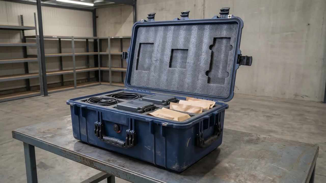
As global supply chains accelerate environmental disclosure, protective cases used to store and transport industrial equipment, medical devices and precision instruments are increasingly pulled into the carbon accounting of procurement teams. Experience shows that for a standard rotomolded protective case, roughly thirty percent of the cradle-to-grave emissions come from case body material and molding energy, and a sensible lightweighting plus reusable design can cut per-turn emissions by more than forty percent without lowering the protection grade. This article focuses on the case itself: the system boundary of carbon footprint, the common standards, material and structural decarbonization paths, and actionable measurement steps, so that procurement, R&D and ESG teams can build a reusable case-emission management framework. We deliberately treat the container as the product under study and exclude the goods carried inside, unless the case supplies active thermal-control energy.
1. Definition and System Boundary of Packaging Carbon Footprint
The carbon footprint of packaging refers to the total greenhouse gas emissions generated within a defined boundary for a protective case, expressed as carbon dioxide equivalent (CO2e). For durable items such as cases, the first question of the boundary is "where to stop": do we count only up to the factory gate ("cradle to gate"), or do we cover use, maintenance, recycling and disposal ("cradle to grave")? The choice is not cosmetic. A cradle-to-gate view favors lightweight one-way cartons, while a cradle-to-grave view rewards a robust reusable case that spreads its manufacturing emission across many turns.
In defense, medical and high-end instrument industries, buyers usually require the cradle-to-grave basis because a single case may circulate dozens of times or serve for many decades. Take a rotomolded polyethylene case: the ex-works emission is roughly the sum of resin emission and rotomolding energy; if it circulates fifty times, the per-turn emission drops sharply. The boundary therefore decides the conclusion, and fixing it early prevents misleading comparisons later in the program.
When setting the boundary, define the unit processes inside the system: shell molding, liner foaming, hardware latches, sealing strips, printing and labels, and the packaging consumables such as cartons, pallets and stretch film that ship with the case should all be counted. The instrument or ammunition inside is generally excluded unless the case provides active thermal control energy. A clear boundary is the premise of comparable and auditable data. The labeling convention can follow the guidance in Packaging Carbon Label, whose functional-unit and data-quality rules can be reused directly.
Three further boundary decisions matter. First, the cutoff criterion: when a unit process contributes below a declared threshold, often about one percent of total emission, it may be omitted after disclosure, but key materials such as shell resin, metal hinges and sealing strips must always be retained. Second, allocation: if one shell serves several product lines, its emission is split by mass, turn count or value, and shared mold and line energy is split by output. Third, the functional unit itself, typically "emission per standard turn of one case", must be stated explicitly so that different case families stay comparable.
2. Life Cycle Stages of a Protective Case
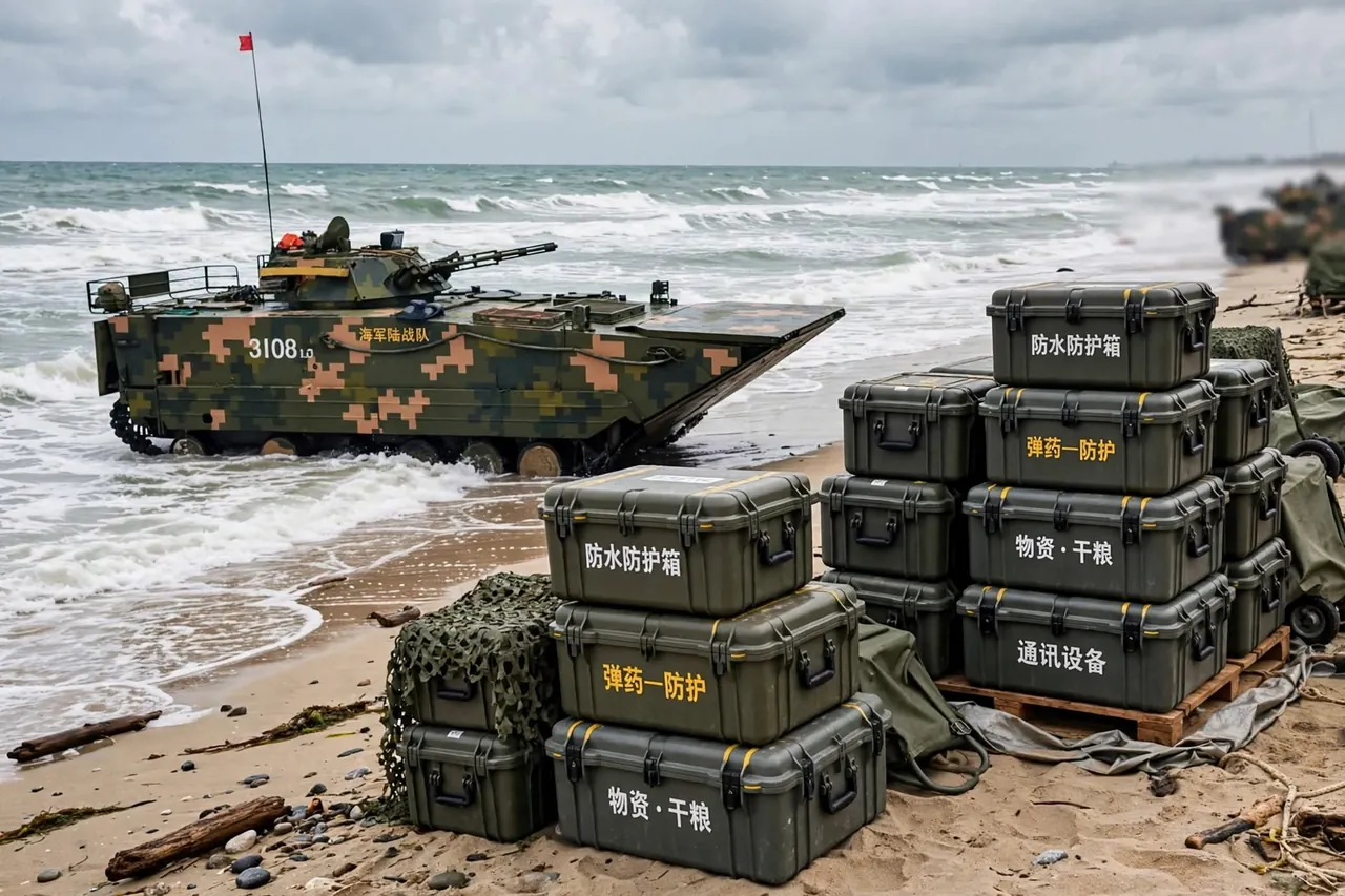
Viewed through a life cycle lens, a protective case divides into five stages: raw material acquisition, case manufacturing, distribution transport, use and maintenance, and recycling and disposal. Each stage has clear emission sources and corresponding reduction levers, and mapping them is the first analytical step before any data collection begins.
The raw material stage emits mainly from industrial production of resins, metals and additives, for example the polymerization of polypropylene (PP), acrylonitrile butadiene styrene (ABS), polycarbonate (PC) and the smelting of aluminum profiles. The manufacturing stage centers on rotomolding or injection heating energy, mold preheating, cooling and post-processing. The distribution stage scales with empty-case weight: the heavier the empty case, the higher the per-shipment emission, which is why lightweighting matters so much for long sea freight.
The use and maintenance stage is often neglected: repeated opening ages seals and wears latches, requiring spare parts whose replacement adds emission; disciplined cleaning and storage extend case life and amortize cumulative emission. The end-of-life stage can yield a carbon credit if the shell enters a recycled-material stream ("avoided virgin production"), or it produces terminal emission if landfilled or incinerated. This stage thinking is exactly what Circular Packaging Protective Case emphasizes by bringing use and recovery into a positive loop.
To make the stage view operational, enterprises should build a "stage emission share baseline table" that breaks last year's case emission by the five stages for every model and flags the largest contributor as the priority improvement target. In experience, material and manufacturing together dominate most rotomolded cases, so decarbonization budget should flow there first rather than into logistics tweaks that represent under ten percent of the total. Packaging consumables used alongside the case, such as corrugated outer cartons and pallet wrap, also belong in this stage view and should not be overlooked when the case is shipped as a packed unit.
3. Common Accounting Standards and Methods
Three mainstream standards are used for product carbon footprint. First, ISO 14067, "Greenhouse gases - Carbon footprint of products - Requirements and guidelines for quantification and communication", which sets functional unit, system boundary, data quality and allocation principles and is widely accepted by exporters. Second, the GHG Protocol product standard, which emphasizes scope 1, 2 and 3 classification logic and eases linkage with organizational carbon inventories. Third, PAS 2050, "Specification for the assessment of the life cycle greenhouse gas emissions of goods and services", long used for packaging and fast-moving goods with mature methods.
For protective cases, the cradle-to-grave basis is usually paired with a functional unit such as "emission per standard turn of one case (load, transport, recover)". This compares a one-way wooden box fairly against a reusable rotomolded case. Primary data (own energy meters, supplier emission factors) should be preferred; secondary data (industry-average databases) is used only where measurement is impossible, and every such substitution must be flagged.
ISO 14067 also requires an uncertainty rating (high, medium, low) and a data-quality description, so the report should state which figures come from measurement and which from databases, letting customers and auditors judge robustness. Where a product category rule (PCR) exists, it should be followed so that the resulting environmental declaration is recognized by downstream programs. Carbon accounting and chemical compliance are two systems: the former governs greenhouse gases, the latter governs restricted substances. Cases exported to the EU often also need RoHS, REACH and CE under Chemical Compliance for Cases; the two should be listed separately to avoid confusion and double counting.
Allocation deserves special care. If one shell is shared across several instrument families, emission is split by mass, turn count or value, and shared mold and production-line energy is split by output volume. The chosen method visibly shifts the result per case, so it must be documented in the methodology chapter and kept consistent year to year and across models to preserve comparability.
4. Material Selection and Its Carbon Impact
Case body material is the first lever on emission. The emission intensity of common engineering plastics differs markedly in typical values: recycled polypropylene is usually below virgin PP, virgin PP below ABS, and PC higher because of energy-intensive polymerization; on the metal side, aluminum profiles have far higher smelting emission than plastics, while stainless steel compensates through weather resistance and service life. Selection must weigh not only per-kilogram emission but "mass needed to reach the same protection grade".
A simplified typical ranking by cradle-to-gate intensity, expressed in grams CO2e per kilogram of resin, places recycled PP lowest, then virgin PP, then ABS, with PC and especially aluminum at the high end. These are planning values, not certified figures, and they shift with the supplier's energy mix. The practical question is how much material each design needs: a thick-wall rotomolded polyethylene shell may use more total mass than a thin injection shell, yet avoid metal reinforcement, so the final emission can land close together.
Take an IP67-rated case (per IEC 60529, corresponding to China's GB/T 4208): a rotomolded polyethylene shell achieves sealing through thick integral molding, whereas a thin-wall injection case often needs more ribs and metal hinges to compensate strength, so the final mass and emission may not differ much. Where electromagnetic shielding is required, the metallic coatings in EMC Shielding Case Guide raise emission significantly and must be balanced by longer life.
The most friendly path is to prefer shells with a recycled-content ratio and to mark that ratio clearly. Using recycled content also ties into the performance limits described in Recycled Material Protective Case, which needs validation of impact strength and low-temperature brittleness so the protection grade is not downgraded. Glass-fiber or mineral fillers can cut resin use while holding stiffness, attacking emission from both "less material" and "lower intensity" sides, but high filler share complicates later sorting and should be weighed against recyclability. Additives such as flame retardants (UL 94 rated halogen or halogen-free systems), UV stabilizers and color masterbatches add emission through synthesis energy and should be minimized by using high-efficiency concentrates.
5. Wall Thickness and Weight Reduction Design
Weight reduction is the most direct and cost-effective case decarbonization. Case emission is approximately proportional to material mass, and mass is set by wall thickness, rib layout and reinforcement. Without lowering the vibration-drop protection of MIL-STD-810H or the transport grade of ISTA, topology optimization can thin non-loaded walls and add ribs in loaded zones to "replace thickness with shape".
In experience, for a same-size rotomolded case, stepping average wall thickness down one notch with reasonable ribs can cut single-case mass by about ten percent, and raw material plus molding energy fall together. The key is to keep enough wall at drop zones (corners, edges, wheel mounts) while thinning flat areas. Weight reduction must be paired with seal verification to avoid lid deformation that lowers the IP grade, because a lighter lid that leaks defeats the purpose of the container.
Handles, wheel sets and trolley handles are also weight targets. Glass-fiber reinforced nylon can replace some metal parts while keeping load capacity. This structural thinking matches the "achieve equal function with less material" principle promoted in Packaging Reduction Design. Finite element analysis can predict stress concentration before tooling, so material is removed precisely from low-stress regions, avoiding local strength loss and reducing trial-mold cycles that waste energy and scrap.
A "weight-reduction red line" should be set: any weight plan is released only after passing drop, stacking and seal validation, and brute thinning for a number is forbidden. Wall thickness, rib height, fillet radius and the weight-reduction ratio should be written into the controlled drawing as the inspection baseline for production consistency, preventing wall drift in volume manufacturing from quietly erasing the decarbonization gain. For injection cases, uniform thin walls also improve cycle time and cut per-part energy, reinforcing the emission saving from the mass reduction itself.
6. Carbon Comparison of Liner Materials
The liner is an underrated source of case emission. Common liners include EPE (expanded polyethylene), EVA (ethylene vinyl acetate), PU (polyurethane) foam, PE foam and recycled foam; their emission difference comes mainly from raw material and foaming energy. EPE uses physical foaming with relatively low process energy; EVA and PU, through copolymerization or chemical foaming, typically have higher per-mass emission; recycled foam, using recovered material, emits clearly less than virgin versions.
A simplified per-kilogram ranking places physically foamed EPE and recycled PE foam at the lower end, with EVA and PU higher because of their chemistry. As with shells, the decisive metric is per turn rather than per piece: a longer-lived, re-cuttable EVA liner may beat a cheap foam replaced often. For odor- and extract-sensitive medical, food and optical instruments, low-odor low-emission foam should be preferred, against the criteria in Eco-Friendly Lining Material.
A reminder: liner emission must not obscure its protection value. If insufficient lining damages the instrument and triggers batch rework or scrap, the implied emission far exceeds the liner itself. Therefore decarbonization cannot sacrifice buffering; it should achieve a win-win through precise cavity design and cushion validation. The forming method also affects emission: CNC-milled EVA creates offcuts that, if collected and regranulated, keep emission controlled, while molded liners carry higher one-time tooling energy but lower per-unit emission at volume.
For multi-variety small-batch orders, pre-cut and field milling are more flexible, but a offcut recovery ledger should be kept to close the material loop. Density choice matters too: a denser foam protects better at lower thickness, so specifying the minimum density that meets the drop test can reduce both mass and emission while keeping the cushion credible. Liner adhesion should use mechanical locating rather than permanent glue so the foam can be removed and recycled at end of life.
7. Molding Process Emissions: Rotomolding vs Injection
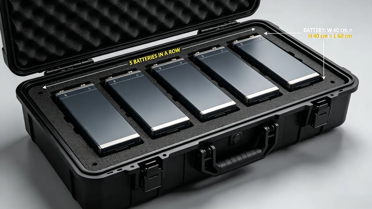
The molding process directly sets manufacturing energy. Rotomolding heats at low temperature with long cycle, low tooling cost, and suits multi-variety small-batch and large integral shells. Injection uses high temperature, high pressure and fast filling, with fast cycle for mass production but high tooling investment and strict wall-uniformity needs. Per-part energy of rotomolding is usually higher in typical values because of the long heating cycle; injection can amortize unit energy when volume is large enough.
Cycle energy can be planned roughly: a rotomolded large shell may consume several kilowatt-hours of oven energy per part because the mold and resin sit in heated air for many minutes, whereas an injection machine concentrates energy in a short fill-and-pack stroke and cools quickly, so per-part electricity falls as cavitation and volume rise. These are planning figures; the real number comes from the factory meter.
Yield also affects emission: rotomolding forms integrally with few welds and high seal reliability, so rework is low; injection, if gate or rib design is poor, easily produces shrinkage and warpage, and scrapped parts add emission. Thus manufacturing emission should include yield as a multiplier, not just nominal energy. A one percent scrap rate quietly adds one percent to the effective per-good-part emission.
For decarbonization, process choice must match volume and life: small-batch, long-life, customizable cases fit rotomolding; high-volume, stable-structure, high-precision cases may consider injection. The comparison is detailed in Rotomold vs Injection Case Guide. Energy structure is decisive: if the plant runs on green power or recovers waste heat, rotomolding's long-cycle disadvantage shrinks, so emission math must overlay the grid factor and cannot judge process merit apart from where it is made. Mold maintenance, regrind reuse of sprues and runners, and oven insulation upgrades are practical levers that cut process emission without changing the part design.
8. Seals, Latches and Hardware Carbon Accounting
Sealing strips, latch locks, hinges and wheel sets are small but their cumulative emission is not negligible. Seals are mostly EPDM (ethylene propylene diene monomer) rubber or TPE (thermoplastic elastomer); rubber vulcanization and elastomer polymerization both emit. Metal latches and stainless hinges come from smelting and machining. Accounting should list each item by "mass times corresponding emission factor" and add the replacement emission of the use stage.
Three reduction strategies exist. First, reduce unnecessary metal parts and replace some stainless parts with engineered plastic latches. Second, choose long-life seal materials to extend the replacement cycle; for example weather-resistant EPDM needs fewer replacements in long outdoor service. Third, standardize hardware so spares are cross-compatible across models, cutting maintenance emission and inventory waste. Seal aging behavior is further discussed in Case Seal Aging and Replacement.
Latches and labels also touch compliance: exported products often need CE and RoHS, and metal coatings must meet the REACH restricted list. Managing compliance and emission in one bill of materials avoids duplicate sampling and testing energy. The pressure-equalization valve used on airtight cases, a small assembly of metal mesh and polymer membrane, also adds emission; on altitude-changing air freight it is essential, but should be minimized to avoid material and emission for redundant function.
A practical accounting move is to assign each hardware item a part number with a linked emission factor in the component library, so every new case design auto-sums its hardware emission from the bill of materials. Standardizing on a short list of approved latches and hinges then lets procurement buy in volume, lowering both unit cost and the embedded emission of frequent small production runs. Tracking actual replacement intervals in the field closes the loop by confirming whether the assumed service life used in the model matches reality.
9. Transport and Logistics Emissions
Empty-case weight amplifies transport emission. On trans-ocean sea freight, every extra kilogram of empty-case weight linearly raises cumulative emission over the long haul; for air-shipped high-value equipment, weight is a double constraint of cost and emission. Thus lightweighting in logistics often outweighs its effect in manufacturing, because the case is moved many times across its life.
Beyond weight, loading efficiency matters: whether cases can stack, whether stack corners pass Case Stacking Structure validation, and whether they fit standard pallets decide how many cases one shipment carries. Foldable or nesting designs compress volume on the empty return leg and lower return deadhead emission, sometimes cutting return volume by more than half versus rigid cases.
Mode choice is large. Sea freight has low emission per ton-kilometer but long transit time; air freight is orders of magnitude higher per ton-kilometer and should be reserved for urgent high-value loads; rail and road sit between. The right comparison uses the actual lane, not a generic factor. Environmental stress testing also matters: performance under MIL-STD-810H and ISTA in temperature, humidity, vibration and drop decides damage rate; lower damage means less implied emission from reshipment and rework. Logistics emission accounting should advance together with the lightweighting goal of Packaging Reduction Design.
For a circular fleet, separate the outbound loaded leg from the empty return leg in the calculation: the loaded leg is charged on total shipment mass, the return on empty-case mass, and the weighted average reflects the real per-turn emission of the loop. Nesting rate, return radius and recovery-network density then become first-order variables rather than footnotes, and they explain why two apparently similar cases can show very different logistics emission in the same program.
10. Reuse and Circular Turnover Logic
Reuse is the core logic of case decarbonization. A one-way wooden or paper box is scrapped after one trip and its emission is sunk; a rotomolded case can circulate dozens to hundreds of times, spreading ex-works emission across every turn. In experience, once circulation exceeds a threshold (depending on case life and maintenance), the per-turn emission of a reusable case falls below the one-way option.
Building a circular system needs three supports. First, identification and tracking: tag each case with a code recording turn count and repair history, following Case Asset QR Code Tracking. Second, standardized dimensions so one batch serves different lines and customers. Third, recovery and refurbishment: weld-repair broken shells or crush-recycle them. These elements are systematically laid out in Reusable Transit Case Program.
Circular reduction must also account for "return logistics": if the empty-return distance is too long or loading too low, the economic and environmental gain erodes. Therefore return radius, recovery network density and nesting rate are variables that must enter the reduction calculation. A pragmatic start is an in-park or regional closed loop, where return distance is short and turn counts accrue fast, proving the saving before the network expands.
The financial case reinforces the carbon case: a reusable case with a higher first cost but low per-turn emission beats a cheap one-way box once the break-even turn count is passed, and the same data feeds both the total-cost model and the carbon model. Cleaning, inspection and re-certification between turns should be counted as use-stage emission so the loop is not silently credited with free maintenance. Recording actual turns per case then lets the per-turn emission be updated from an estimate to a measured result.
11. Recycling and End-of-Life Carbon Balance
How a case ends its life decides whether emission "closes" or "leaks". Entering a formal recovery system, crushing and regranulating PP or PE for non-structural parts yields a credit from avoided virgin production; mixed heavy-metal coatings or complex composites raise sorting difficulty and lower recovery value. Design for recyclability from the start: reduce dissimilar-material gluing, use easily separated metal inserts, and mark material and recycling symbols on the shell.
The two main end paths are landfill and incineration. Landfill produces almost no energy recovery but occupies land; incineration recovers some heat yet releases CO2, and with chlorine- or fluorine-bearing additives may emit others. The most favorable path is "extend use, recover formally, regenerate". Disposal rules can combine Packaging Waste Management with the sorting guidance of Recycling Mark Cases.
On economics, a single-material shell (pure PP or pure PE rotomolded case) has far higher recycling value than a multi-layer composite or a metal-plastic bonded part; so where protection allows, prefer a single recyclable material and mold the resin code and recycling triangle onto the shell. For unavoidable metal inserts, use clips or screws instead of adhesive so they separate cleanly at recovery, lifting the purity and the carbon credit of the regrind.
A recovery ledger should record mass actually returned and the fate of each case, because the avoided-emission credit is only real when the material re-enters production rather than being landfilled despite good intentions. Where local recovery infrastructure is weak, specifying a take-back route with the supplier turns the end-of-life stage from a liability into a credited, auditable saving and keeps the cradle-to-grave balance honest.
12. Practical Steps to Measure Case Carbon Footprint
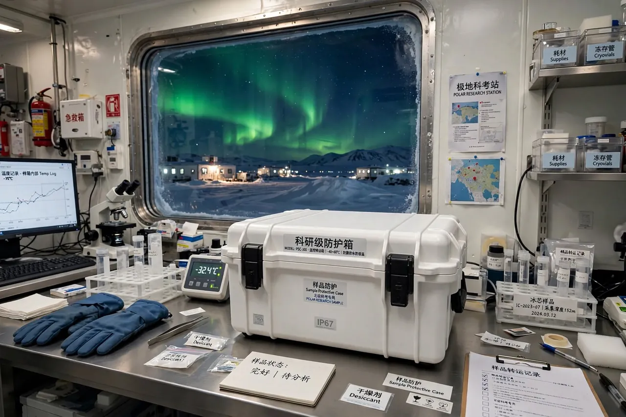
Below is an actionable measurement flow for enterprises to build their own model. Step one, define the functional unit and boundary; the suggested unit is "emission per standard turn of one case (kg CO2e/turn)". Step two, draw the process flow and list unit processes of material, energy, auxiliaries and waste. Step three, collect primary data: rotomolding or injection electricity, purchased mass and supplier factors, transport distance and mode. Step four, pick an emission-factor database, fill gaps with secondary data and mark uncertainty.
Step five, calculate line by line and aggregate (see table). Step six, run sensitivity analysis to find the dominant stage (usually material and manufacturing). Step seven, set a reduction list and re-check boundary consistency. A typical calculation table follows:
| Stage | Unit process | Activity data | Factor (typical) | Emission kg CO2e |
|---|---|---|---|---|
| --- | --- | --- | --- | --- |
| Material | PP pellet | per case mass | industry average | primary data |
| Manufacturing | rotomold heat | kWh per case | grid factor | energy x factor |
| Transport | empty sea | mass x distance | sea factor | mass x dist x factor |
| Use | seal replace | spare mass | corresponding | cumulative |
| Recovery | regranulate | recovered mass | avoided credit | negative offset |
Data collection tips: meter the molding machine per shift and divide by good parts, not by started parts, to embed yield; ask resin suppliers for cradle-to-gate factors tied to their energy mix; record the real lane and load factor rather than a generic assumption. The sensitivity step is where the model earns its keep: vary the recycled-content ratio, the wall thickness and the turn count one at a time to show which lever moves the total most, then spend the decarbonization budget on that lever.
After measurement, write results into a product environmental declaration or carbon label file, keeping the same convention as Packaging Carbon Label so external disclosure is consistent and traceable. The final step is to feed the number into procurement review: include per-turn emission in the scoring of Green Procurement Cases so low-carbon cases gain a quantifiable edge in tenders, turning the calculation into real commercial preference and real emission reduction.
13. Engineering Low-Carbon Cases into Delivery
Turning decarbonization from concept into product needs the supplier's co-design ability across material, structure and process. Taking JUNZHIJIA engineering practice as an example, it can introduce a recycled-content plan at the design stage and combine it with rib topology optimization to reduce weight without downgrading protection; it standardizes and extends the life of seals and hardware to lower use-stage maintenance emission; and it can provide the data sheets and test documents needed for carbon calculation to support ESG reports and export compliance.
For EU exporters, JUNZHIJIA can also help complete CE, RoHS and REACH documents and archive them with the carbon file, reducing energy and cost from duplicate testing. Similarly, the supplier audit in Green Supply Chain Cases and the tender criteria in Green Procurement Cases can serve as acceptance evidence for case decarbonization capability.
To restate: the bottom line of case decarbonization is no downgrade of protection. Any lightweighting, recycled substitution or process change must pass IP grade, drop and vibration validation. Only emission reduction achieved under equal or better protection is truly sustainable, and the validation report should sit beside the carbon report as a dual deliverable. For products facing IP67 immersion testing (per IEC 60529, GB/T 4208) or ISTA transport tests, archiving both files together lets customers pass compliance review in one pass.
Supplier data quality is the quiet driver of credible numbers. A case maker that can hand over per-part electricity, resin batch factors and verified turn-count history lets the buyer skip secondary estimates and report a tighter uncertainty band, which auditors trust more. Choosing a partner with in-house molding, liner cutting and hardware standardization therefore lowers not only the case emission but also the effort and emission of the accounting itself, closing the loop between making the case and proving its footprint.
FAQ
Q: To which stage should a protective case carbon footprint be counted for the most reasonable result? A: For industrial and military protective cases, the cradle-to-grave basis combined with circulation count is the most reasonable. Because such cases are long-lived and reusable, counting only ex-works emission overstates the advantage of one-way packaging, while a full-life view truly reflects the long-term reduction value of reusable cases. The boundary should include shell, liner, hardware seals, label printing and recovery, and exclude the contained equipment unless the case provides active thermal control energy. Once the basis is fixed in the report, it enables year-on-year comparison and cross-model benchmarking. A stable boundary is the premise of auditable and comparable disclosure across product families and procurement cycles. For shared shells serving several product lines, allocate emission by mass or turn count and document the method so different years and models stay comparable. Cutoff rules may omit processes below a declared share, but key materials such as shell resin, hinges and seals must always be retained to keep the conclusion robust.
Q: Will a recycled-plastic protective case show a clear drop in protection grade? A: The effect of recycled content on protection depends on addition ratio, feedstock purity and process control, and cannot be generalized. At a reasonable blend ratio, with rib and wall compensation, a rotomolded case can still maintain IP67 and the specified drop standard. The key is incoming inspection of recycled material for impact strength, low-temperature brittleness and melt flow rate, plus IP and drop validation on the first batch. For harsh outdoor or water-exposed scenarios, prefer validated grades and consult the performance limits in Recycled Material Protective Case so reliability is never sacrificed for decarbonization. Recycled content should be treated as a design variable, not a compromise, and supplier batches vary, so keep a qualified-supplier list and a per-batch retain sample system. With stable feedstock and verified process windows, protection grade can hold while the per-case emission falls, which is the outcome every procurement spec should require. Documenting the recycled ratio on the label also supports downstream ESG reporting and keeps the claim auditable across the whole contract period.
Q: Does lightweighting make the case easier to break when dropped? A: Scientific weight reduction is not simply shaving thickness; it uses rib topology, keeping thickness at loaded zones and thinning flat areas to "replace thickness with shape". As long as drop-critical zones such as corners, edges and wheel mounts keep enough wall, and the MIL-STD-810H and ISTA drop items are re-validated, protection can stay the same or even improve. The real risk comes from unvalidated brute thinning, so any weight plan should attach drop and vibration test records. The lower self-weight from lightweighting also reduces transport damage rate, indirectly cutting the implied emission from reshipment and creating a positive loop between decarbonization and protection. Validation evidence is non-negotiable, and the weight-reduction ratio, wall map and test conclusion should sit in the controlled drawing as the production inspection baseline so volume manufacturing cannot quietly drift back to a heavier, higher-emission shell. For a case customized per project, the same drawing control should travel with the tooling release so every reorder keeps the validated weight and the same certified emission.
Q: How many turns must a rotomolded case complete to be lower carbon than a one-way wooden box? A: The break-even turn count depends on the single-trip emission of both packages and case life, and must be calculated from specific size, wall thickness and transport distance rather than a universal number. In experience, once a rotomolded case circulates to a certain scale, typically tens of turns, its per-turn emission falls below that of a one-way wooden box; adding return nesting and formal recycling widens the advantage. Enterprises should calculate based on their own logistics radius and recovery network density, and periodically recheck the actual turn count to refresh the conclusion. Treat the threshold as a managed metric, not a borrowed assumption from another operation, and count cleaning and re-certification between turns as use-stage emission so the loop is credited honestly. A regional closed loop with short return distance reaches break-even fastest and gives the cleanest measured proof before the network expands outward. A simple turn-count dashboard on the asset tag makes the break-even visible to operators and prevents premature retirement of still-usable cases that still carry unused emission potential.
Q: Which liner foam has the lowest carbon emission? A: By raw material and process, physically foamed EPE and recycled-content PE foam usually emit less, while EVA and PU carry higher process energy through copolymerization or chemical foaming. But "lowest" should be judged per turn, not per piece: a longer-lived, re-cuttable EVA liner may have lower per-turn emission than a cheap foam replaced often. For medical, food and optical instruments, low-odor low-emission foam is also required, so prefer eco-friendly grades. In short, liner decarbonization must not sacrifice cushion performance; balance emission and protection through precise cavity design. The liner is a protective asset, and its emission should be evaluated against the value it protects across the whole life. Density choice helps too: the minimum density that still meets the drop test reduces both mass and emission. Use mechanical locating instead of permanent glue so the foam can be recovered at end of life. Matching liner density to the actual shock load also avoids over-specifying foam, which would add mass and emission for no protective gain in the field.
Q: Are carbon footprint accounting and RoHS, REACH the same thing? A: No, they govern different dimensions. Carbon footprint accounting targets greenhouse gas emission, measuring the CO2e of a case across its life, usually under ISO 14067, GHG Protocol or PAS 2050. RoHS and REACH are chemical compliance, restricting substances like lead, cadmium and phthalates, and are market-access requirements for the EU. In engineering documents the two should be listed separately: carbon uses emission-factor method, chemical compliance uses substance testing and declaration. Exporters often prepare both file sets; the list and templates in Chemical Compliance for Cases help avoid mixing the two bases. Keep the scopes distinct to satisfy auditors and customers. The data sources also differ: carbon relies on energy and logistics records, chemical compliance on supply-chain substance declarations, so managing both inside one bill of materials improves efficiency without blurring the two very different conclusions. Sharing one validated bill of materials across both reports also shortens lead time when a new case variant enters the same program and must clear the same two gates.
Q: When transport distance is very long, how large is the effect of empty-case weight? A: Empty-case weight affects long-haul transport emission strongly and almost linearly. On trans-ocean sea freight and air freight, every extra kilogram of empty-case weight raises cumulative emission in proportion; for air-shipped high-value equipment, weight also directly drives freight cost and emission. Therefore lightweighting in logistics often outperforms its effect in manufacturing. Loading rate matters equally: stackable cases that fit standard pallets and nest on return compress volume and raise per-shipment load, further amortizing per-unit emission. Design references for stacking and reduction should be consulted early in the program to capture the full logistics saving. For a circular fleet, separate the outbound loaded leg from the empty return leg in the math, then weight them by actual turns; nesting rate, return radius and recovery density then become first-order variables explaining why similar cases differ sharply in real logistics emission. Reviewing the lane every season catches shifts in carrier mix or load factor that would otherwise quietly change the per-turn number without anyone noticing the drift.
Q: How should a case be disposed of after service to minimize carbon? A: The most carbon-friendly path is the closed loop of "extend use, recover formally, regenerate", rather than direct landfill or incineration. Design for recyclability from the start: reduce dissimilar-material gluing, use easily separated metal inserts, and mark material and recycling symbols on the shell to ease later sorting and regranulation. Entering a formal recovery system lets regranulated material replace some virgin feedstock, earning an avoided-production credit. If only end disposal is possible, incineration with heat recovery beats landfill but still falls below regeneration. Enterprises should keep a recovery ledger and align with Packaging Waste Management so the carbon balance is verifiable. Prefer a single recyclable shell material and use clips or screws for metal inserts so they separate cleanly; specify a supplier take-back route where local recovery is weak, turning end-of-life from a liability into a credible, auditable carbon credit. Training handlers to separate shells from mixed inserts at the depot is what turns the design intent into an actual recovered mass that the ledger can record.