

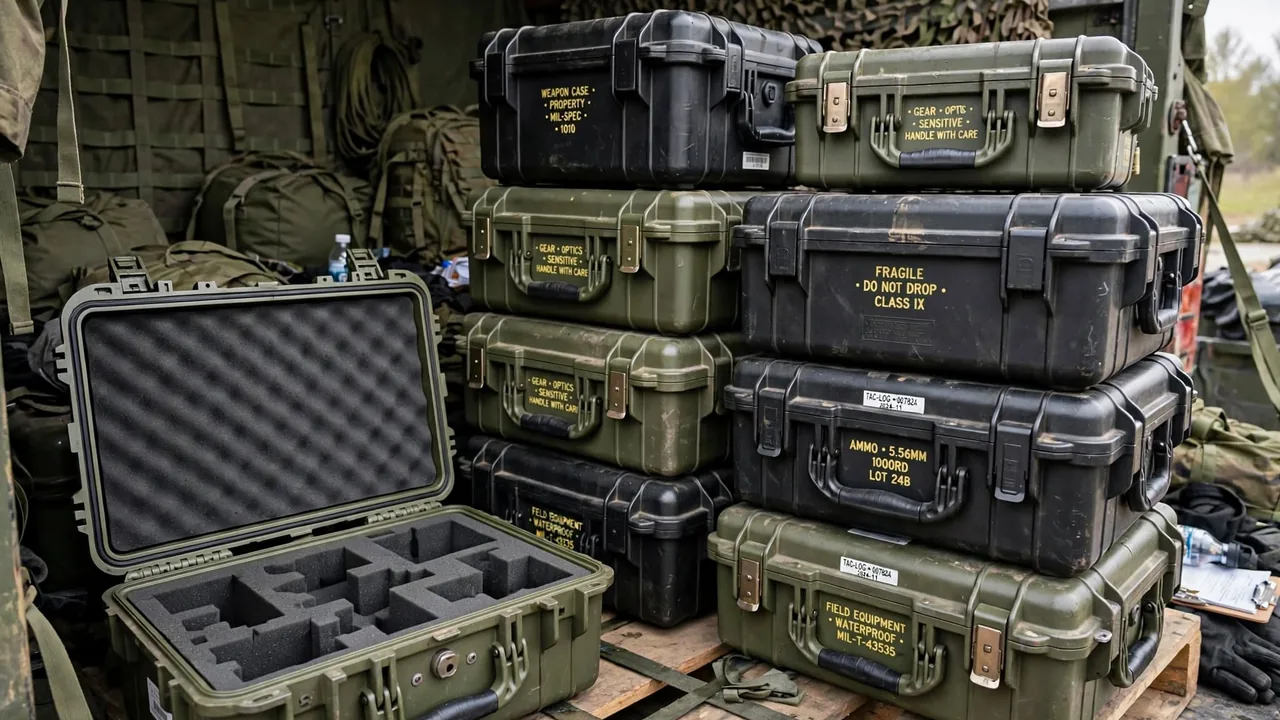
A sensor case is a protective container built specifically to store and transport pressure, temperature, vibration, displacement, gas, photoelectric and inertial sensors along with their signal-conditioning modules. Sensor internals often include micro-electromechanical structures, thin films, piezoelectric wafers and high-impedance amplifier circuits, and they are extremely sensitive to electrostatic discharge, mechanical shock, humidity swings and particulate contamination. A single unnoticed static discharge can puncture an input stage; a single drop can permanently deform a diaphragm or cantilever; either outcome throws a whole measurement system out of calibration. A sensor case must therefore be engineered like an instrument case, with simultaneous attention to ESD control, shock isolation, sealing, shielding and humidity management. This article explains how sensor cases are specified across failure mechanisms, anti-static materials, shell structure, liner cushioning, dust sealing, latch load-bearing and certification, and connects that thinking to Optical Instrument Case: Zoned Protection and Shock Isolation for Precision Optics, Detection Instrument Case: Protective Storage for Field Test Equipment and Instrument Cases: Precision Meter Transport & Protection so that a case becomes a properly managed instrument enclosure.
Application Scenarios and Protected Objects
The objects served by a sensor case are remarkably diverse. Grouped by measured quantity, they include pressure sensors, temperature probes and thermocouples, vibration and accelerometers, displacement and proximity switches, flow and level sensors, gas and smoke sensing elements, photoelectric and image sensors, and inertial measurement units. Grouped by form factor, they include threaded cylindrical probes, flange-mounted disc elements, bare-chip modules with flying leads, and modular transmitters that integrate signal conditioning and a communication interface. What they share is small size, concentrated value, fine structure and a workflow that moves from laboratory calibration to field installation. If moisture, vibration or ESD damages the device in transit, field commissioning fails again and again.
In application terms, sensor cases serve electronic reconnaissance units, sensor integrators, research test sites, and environmental monitoring and industrial quality teams. For an integrator, the case must protect the sensor bodies and also hold mounting fixtures, calibration tooling, shielded cables and adapters, so zoning matters even more. A practical split is body layer, accessory layer and spares layer. The body layer uses molded inserts to fix each sensor one-to-one. The accessory layer holds fixtures, brackets and cables. The spares layer holds gaskets, desiccant and small tools, stored by a numbered checklist. With this structure, every stage from calibration to transit to installation to recovery can be counted against fixed positions, preventing sensitive elements from colliding in a mixed load. For high-value sensors that need metrological traceability, the case should carry a one-case-one-file record of calibration dates and assigned crews.
Failure Mechanisms and Protection Goals
Understanding failure mechanisms is the precondition for designing a sensor case. Electrostatic discharge is the most invisible threat: a person walking on a dry floor can carry a potential of several thousand volts, and touching a sensor pin or circuit releases that energy within milliseconds, puncturing insulation or fusing micro-leads. This kind of damage often does not appear as immediate failure but as gradual drift during later use. Mechanical shock and vibration are the second threat: diaphragms, cantilevers and piezoelectric wafers can tolerate only limited strain, and exceeding the threshold produces plastic deformation or cracking that shifts range and zero point. Moisture forms leakage paths across high-impedance circuit surfaces, dust clogs sampling ports and optical paths, and rapid temperature change creates thermal stress between the sensitive element and its packaging.
Against these mechanisms, the protection goals of a sensor case fall into five groups. First, static dissipation and shielding: conductive or dissipative liners and shielding structures suppress charge accumulation and external field interference. Second, shock and vibration cushioning: transport energy is absorbed layer by layer in foam and elastic supports. Third, dust and moisture sealing: water vapor and particles are kept out of the cavity. Fourth, temperature and humidity stability: desiccant and thermal control hold the internal environment steady. Fifth, clean isolation: sensitive elements do not touch, rub or cross-contaminate one another. These five goals connect to the shell material questions raised in Case Shell: Structural Materials and Molding Process of Protective Cases as well as the insert-fabrication guidance in Case Foam Lining: Cushioning and Customization of Case Interiors, which together give a sensor case its base capability.
ESD Design and Shielding Materials
ESD protection is the metric that sets a sensor case apart from an ordinary instrument case. The design idea is not to eliminate static but to discharge it safely and suppress its accumulation. A common approach is to introduce conductive or dissipative material into the liner so that surface resistivity sits in a controlled band, letting contact-generated charge drain slowly rather than release instantly. Typical options include carbon-black-filled conductive foam, fabric coated with a conductive layer, and metallized shielding bags. It matters that conductive and dissipative are different strategies: conductive material drains faster but can create short-circuit risk, while dissipative material drains gently and suits the liner that directly touches a sensor.
Shielding addresses external electric fields and electromagnetic interference. A metallized liner or metal foil layer creates a Faraday cage effect that keeps external static fields and high-frequency interference outside, protecting sensors with high-impedance input stages. For smart sensors with communication interfaces, shielding also reduces the effect of radio-frequency interference on signals, which is consistent with the RF compatibility thinking in Communication Equipment Case: RF Compatibility and Protection Design. In practice, a shielding liner needs a proper electrical path to the case metal parts and to ground so it does not float at an unpredictable potential. Note also that anti-static liner performance shifts with humidity and contamination: once oil or dust coats the surface, dissipative capability falls, so it should be cleaned periodically with a mild neutral agent and allowed to dry to keep the conductive path stable.
Shell Materials and Structural Selection
Common shell materials for a sensor case include modified engineering plastics, polypropylene copolymer, magnesium-aluminum alloy and composites. Engineering-plastic shells are injection molded, light and dimensionally precise, and they make it easy to place shielding layers and ribs in the wall, so they are the default for most portable sensor cases. Polypropylene copolymer resists chemicals and stays tough at low temperature, suiting environmental monitoring outdoors. A magnesium-aluminum shell is rigid and inherently shielding, fitting applications that need both electromagnetic compatibility and structural stiffness, though it requires anodizing against corrosion. Composites win on weight and specific strength. The trade-offs among similar materials are covered in What Common Plastic Materials Are Used in Protective Cases?.
In structural form, sensor cases usually adopt a clamshell or a drawer layout. A clamshell suits sets with a moderate number of sensors and allows whole-set loading, while drawers let different sensor families be stored in layers with less disturbance to other elements on opening. Rims should be ribbed and rounded, and the corners are best equipped with Case Stacking Corner: Load-Bearing and Alignment Hardware for Stacked Cases for stacking stability. Case types that cross regions by air should fit a pressure equalization valve with a waterproof breathable membrane so high-altitude pressure differential does not bulge the lid or break the seal. Selection should also fix the cavity partitioning plan from sensor size and count, rather than sacrificing fixation accuracy for the sake of versatility.
Liner Zoning and Foam Cushioning
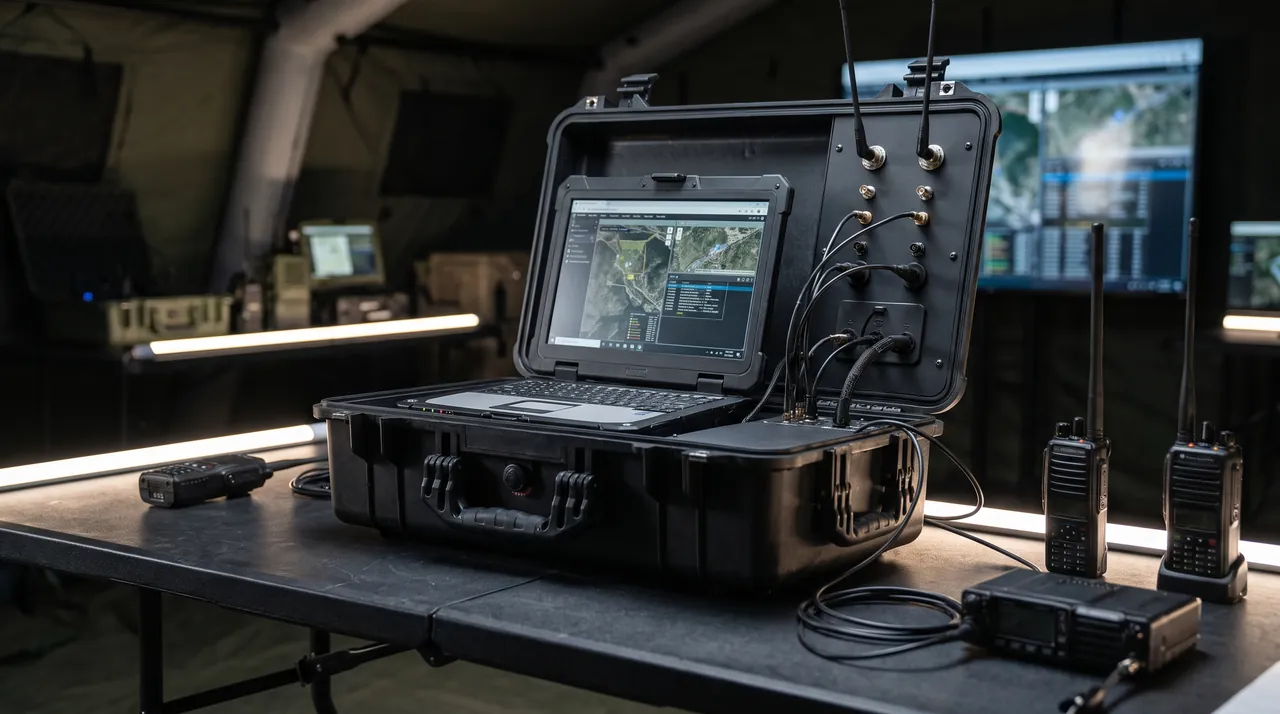
The liner is where fixation and cushioning in a sensor case really happen. The materials in common use include EVA foam, cross-linked polyethylene foam, polyurethane foam and anti-static foam. EVA balances hardness and toughness and molds readily, so it is a natural fit for hard inserts shaped to a sensor contour. Cross-linked polyethylene offers a high closed-cell ratio and low water absorption for humid settings. Polyurethane is soft and is used to wrap bare-chip modules and probe faces. Anti-static foam adds conductive filler to ordinary foam so cushioning and static dissipation come together. The strengths of each foam are discussed in What Foam Should a Protective Case Insert Use? EVA vs EPE vs XPE vs PU Compared.
Zoning should follow the principles of one item per cavity, heavy low and light high, frequently used outboard and sensitive centered. Every sensor should have its own molded cavity matched to the probe thread, flange or connector shape so a generic cavity cannot let it wobble. Sensors with flying leads need a routing channel beside the cavity so the cable follows a fixed path instead of coiling randomly and tugging the body in transit. Direction-sensitive elements such as inertial measurement units and photoelectric sensors need keyed seating so the stowed orientation is identical every time and the calibration state is preserved. The liner should also keep enough cushioning between sensor and wall to route the main impact path into the corners rather than into the device. In general, the finer the zoning, the more completely the sensitive element is constrained in six degrees of freedom, and the lower the risk of displacement and rubbing.
Dust and Water Sealing
Sampling ports, optical windows and electrical connectors on sensors are the most exposed to dust and moisture, which makes sealing and dust exclusion defining metrics for a sensor case. The joint where the lid meets the body is shut by a Case Seal Strip: The Key Waterproof and Dustproof Accessory for Protective Cases. Quality gaskets are typically made of EPDM or silicone; they shrug off ozone and UV, resist aging, and stay springy in the cold. Profiles range from round to hollow rectangular to lip seals, and the lip form presses itself to the closing lid, which raises reliability. Where rain and brief immersion are possible, the case should carry an IP67 rating, which means full dust protection and brief immersion at a stated depth with no leakage.
How well sealing works depends not only on the gasket but on whether latch compression is even. A latch clamped too tightly distorts the case and opens a narrow gap that ruins the overall seal, while spreading the latches symmetrically balances the load around the rim. Periodic upkeep should wipe the gasket so grit cannot lodge and press leak paths into it, and should watch for hardening or splits after extended service; the procedure is described in What to Do When a Protective-Case Gasket Ages. For sensor modules with high-impedance circuits, desiccant and humidity indicator cards make any moisture change visible. One reminder: the tighter the seal, the more a pressure differential is amplified across it, so a case with a breathable valve is preferable for air transport and high-altitude use.
Shock and Vibration Isolation
Shock isolation forms the second pillar of protection in a sensor case. The aim is to turn the stiff union between sensor and shell into an elastic, damped one, so that outside impact is absorbed in stages—foam crushing, elastomer strain and damping loss—and the peak acceleration felt by the sensor is reduced. Diaphragms, cantilevers and piezoelectric wafers tolerate only small strain, so damping design has to satisfy two goals at once: isolate high-frequency vibration and limit large low-frequency displacement. The first calls on soft foam and damping material to absorb high-frequency energy; the second relies on sensible compression to keep displacement from being amplified near resonance.
On the job, stacking the damping in layers usually pays off better than a single thickness. The typical build puts a damping shell layer together with a cushion liner layer: a slim damping film glued to the shell interior mops up high-frequency chatter, and the liner foam absorbs the bulk of the shock. For very sensitive sensors, a silicone pad or an elastic support between device and insert gives a third protective tier. Softness has limits: foam that is too yielding will creep under long vibration and lets the sensor sink out of constraint. Foam density should therefore match device weight and sensitive-axis direction, and before batch issue a free-drop plus simulated-transport vibration check should verify the transmissibility target. For sensors containing magnetic elements, magnetic shielding and the damping parts must also be checked for compatibility, since soft magnetic material can itself disturb a measurement.
Latches, Hinges and Load-Bearing Configuration
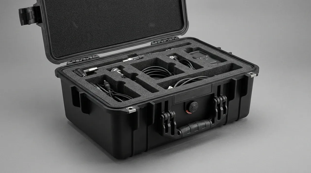
In transit a sensor case takes stacking load and knocks, so the latch must deter theft as well as keep the lid secured. The common family comprises draw latches, butterfly catches, push latches and recessed combination locks. Draw latches keep a simple, load-stable design that suits heavier instrument cases; butterfly catches open and shut quickly for frequently accessed cases; combination locks bring an extra anti-theft tier for unattended moves. Material choice and corrosion resistance also deserve attention, with stainless steel or corrosion-treated fittings preferred so nothing seizes in humid conditions; more points are covered in Case Latch: Pressure and Theft Resistance Hardware for Protective Cases and a buyer's guide to protective-case latch types and clamping force.
Hinges and lid supports are just as important. Since a sensor case is opened often, a hinge of inadequate strength will slacken and skew over the years and then no longer squeeze the gasket shut. A metal-pin hinge fitted with a travel stop keeps the opening angle under control. On high-integration cases with many accessories, an internal cable pouch and tool slot keep attachments from scattering and striking the sensors in transit. For theft deterrence, a steel cable seal or a numbered tag makes any covert opening evident while the case is moving. Remember that latches and hinges are only secondary safeguards; genuine protection of sensitive elements still depends on disciplined procedures and anti-static work habits, with the container serving only as the last physical barrier against risk.
Stacking, Handling and Whole-Case Securing
Labs, stores and vehicles have little room to spare, so sensor cases are commonly piled several layers deep, which calls for dependable stacking ability. Case Stacking Corner: Load-Bearing and Alignment Hardware for Stacked Cases brings upper and lower cases into exact line and carries the upper weight through ribs and corner posts instead of thin walls, so the static load is shared; the mechanics behind it are explained in How Do Protective Cases Achieve Stable Stacking? Stacking Ribs, Locator Bosses, and Interlocking Principles. Stackable height tracks the rated stacking weight of an individual case, its footprint and what the bottom layer can bear; the convention is heavier cases downstairs, lighter ones on top and like sizes together, with a transition board when sizes are mixed and never past the manufacturer's limit.
Handling needs discipline too. A wheeled model is fine for towing on flat ground, but on stairs, gravel and mud it should be carried by its handle. Handles want to sit either side of the center of gravity, so pulling from one side cannot torque the case. When a full column travels, straps together with anti-slip mats should keep it from sliding forward during a hard stop. Stacking copes only with static bearing; road shocks still have to be taken up by the liner, and neither can do the other's job. A sensor case should also avoid sharp tilt and inversion during handling, especially for devices with a liquid reference cavity or a precision mechanism, because tilting can move internal media or misalign the mechanism, so the exterior should carry this-way-up and tilt-warning marks.
Temperature and Humidity Management
However well the case is sealed, moisture can still condense inside a sensor case when day-night temperature swings or high humidity are in play. A damp environment forms leakage paths across high-impedance circuit surfaces, drifting the measurement signal, and over the long run it can corrode metal parts and oxidize contacts. That is why cases usually ship with desiccant, humidity indicator cards or powered dehumidification modules. Silica gel costs little and can be dried out and reused, which makes it the simplest starting point, while color-change silica gives a clear visual reading of moisture take-up. When storage is long or transport crosses climate zones, an electronic humidity readout plus a semiconductor dehumidifier keeps relative humidity inside a safe band.
Correct desiccant use comes down to how much and when. The dose must suit the case volume and the journey length: too little and dehumidification falls short, too much and it may release moisture back in extreme cold. Once gear has been taken out, reseal quickly so outside moisture cannot pour in. If equipment is carried from a chilly location into a warm, damp one, allow it to equalize inside the closed case before the lid comes off, so its temperature slowly matches the surroundings and condensation is less likely. For temperature-sensitive sensors, a phase-change material or an insulating liner can slow the temperature swings that affect zero point and sensitivity. Treating temperature and humidity as variables you can control, in line with the environmental thinking in Precision Instrument Cases: CMM, Spectrometer & Laser Rangefinder Protection, is the most economical way to extend sensor life.
Labeling, Inventory and Calibration Traceability
When a unit looks after several sensor cases at once, labeling and traceability are what keep management efficient. Mark the lid exterior with sensor category, range and serial number, the assigned crew, and this-way-up plus fragile symbols, so handlers and dispatchers see what matters at a glance. The interior carries a gear list, calibration status and stowage numbers so every sensor has its home. Sensors that need metrological traceability should carry a calibration validity label so their status can be verified at both ends of a job. Modern practice also lets a team attach QR codes or RFID tags, enabling scan-based counting and full lifecycle traceability, which moves stock-taking from memory toward data comparison.
Traceability earns its keep especially for sensors. When a sensor drifts or fails, the cause has to be sorted into element aging, shock or moisture during storage and transport, or improper field use. Building a file for the case and its key elements—recording calibration dates, issue and return times, assigned crews and maintenance history—lets a fault review pin down the stage fast. For the anti-static liner, that file should also carry periodic surface resistivity test results, because liner degradation is often the precursor to ESD damage. Label material must also stand up to weather, and critical warnings are best laser-engraved or mounted on metal plates so sun and rain cannot peel or blur them. Still, labeling and traceability must ultimately support compliance work, and any cross-border movement has to satisfy local rules and export-control obligations.
Molding Process and Custom Tooling
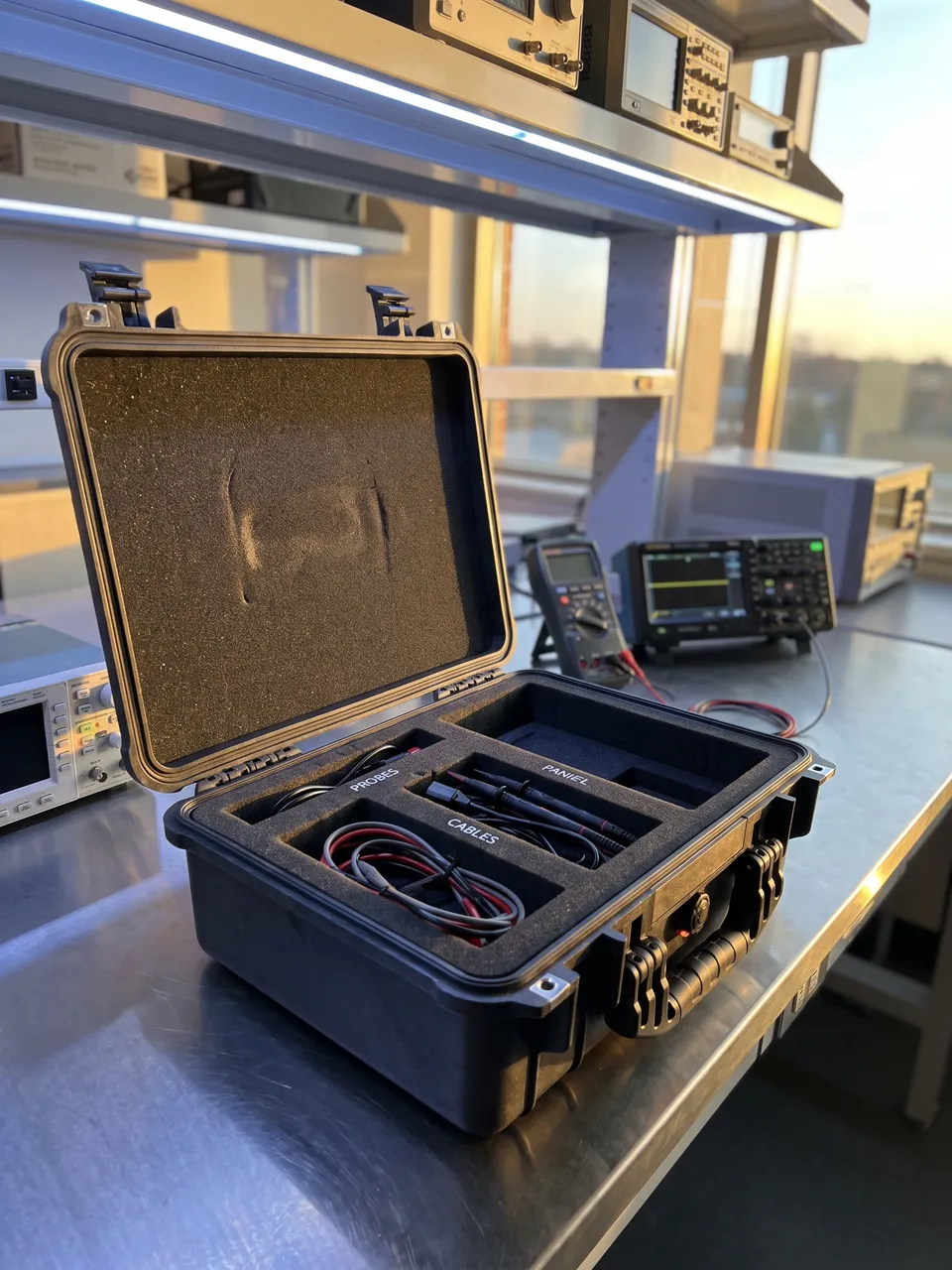
The molding route for a sensor case shapes its strength, sealing and batch-to-batch consistency. Engineering-plastic shells are produced chiefly by injection or blow molding. Injection molding handles intricate, tight-tolerance cases, turning out ribs, latch seats, seal grooves and shielding insert mounting points in one pass, keeping walls uniform and dimensions repeatable. Blow molding serves big hollow bodies, giving structural unity and impact strength at some cost in fine detail. Metal shells, as a rule, come from stamping, bending and welding, after which a surface finish raises corrosion resistance and adds shielding. Ahead of tooling, fix the parting line, draft angle, shrinkage and gate position, then check dimensions and assembly on a trial mold so a production run does not come out with uneven lid gaps or misaligned latches.
Customization usually splits into shell tooling and liner processing. In the shell stage, the external shape, wall thickness, ribs, latch seats and shielding structure are designed from the sensor 3D model. In the liner stage, zoned foam is CNC carved or thermoformed from the device contour and sensitive-axis direction, with an anti-static layer inserted where needed. Before tooling, confirm foam density, color, flame class and surface resistivity, and design support zones at probe faces and lead exits. Although tooling carries higher upfront cost, it maximizes fixed positioning and damping and trims long-term breakage and repair cost. For small, frequently changing batches, a standard shell plus a custom liner can deliver near-custom protection and anti-static performance at lower cost.
Certification, Acceptance and Export Compliance
Although a sensor case is merely a packaging container, its reliability is normally assessed against the general protective-case standards. The usual references are IP ratings, MIL-STD-810H environmental engineering and test methods, and electromagnetic-compatibility specifications covering drop, vibration, rain, dust, salt fog and low pressure. For sensor work, the anti-static performance of the liner and its shielding effectiveness also matter, and the supplier should provide the matching test reports as objective evidence. When the case arrives, a brief inspection is in order: examine it for cracks and distortion, work the latches to check they are smooth, make sure the gasket is intact and evenly seated, check that each cavity fits its device, and confirm the anti-static liner's surface resistivity falls within the agreed range.
A purchase specification ought to spell out at least shell material and wall thickness, liner material and density, anti-static and shielding requirements, sealing rating, latch type, stacking load, temperature range, certification basis and the liner zoning drawing, and it should put the acceptance checklist and critical-batch sampling requirement into the contract so that quality calls rest on a documented basis. Where sensors are costly, one unit should first pass a vibration-table and free-drop review before the rest of the batch goes out. One closing clarification: this article covers only the structure, materials and performance of the sensor case as a packaging container and says nothing about the internal principles or formulations of the protected devices. Moving such equipment across borders or exporting it is subject to local laws and regulations and to export-control rules, and must be assessed by the user alone; nothing here is a compliance finding.
FAQ
Q: What is the essential difference between a sensor case and an ordinary instrument case? A: The essential difference lies in how precisely static and micro-vibration are controlled. An ordinary instrument case mainly solves fixation, cushioning and moisture protection, while a sensor case serves highly sensitive gear with micro-electromechanical structures, thin films and high-impedance circuits, so its core is ESD dissipation, electromagnetic shielding, micro-vibration isolation and cleanliness control. It is stricter in liner surface resistivity, shielding effectiveness, foam density grading, cable routing constraint and tilt-warning marking, and it is often carved one-to-one from sensor 3D data with keyed seating for direction-sensitive elements. A sensor case is therefore not merely about fitting and cushioning, but about dissipating, shielding and holding stable. Buyers should first define the sensitive axis, interface type and ESD sensitivity class of the sensor, then set the liner and shielding configuration, avoiding the trap of substituting an ordinary instrument case and hiding a future failure. Recording the ESD class on the case label itself also warns every handler before the lid is opened.
Q: Should the anti-static liner use conductive or dissipative material? A: The two are different strategies that should be layered by position rather than treated as an either-or choice. Conductive material drains quickly with low surface resistivity, so it suits a shielding layer or grounding face away from the device body. Dissipative material drains gently and can move static charge away over several seconds, making it the better main material for a liner that directly touches a sensor. Placing conductive material right next to a bare chip or pins can create short-circuit and rapid-discharge risk instead of safety. The common approach is therefore a metallized shield or conductive fabric outside to form a Faraday cage and dissipative foam inside to support the device. With either material, confirm the surface resistivity target and the grounding path, because a floating shield is not only ineffective but can accumulate charge. Daily care should also keep the liner free of oil and dust, or dissipative capability drops sharply. A simple surface resistance meter check at every stock-take catches the slow drift before it becomes a shock event.
Q: Why does a sensor case place such emphasis on micro-vibration isolation? A: Because the core sensing structures of a sensor tolerate far less micro-vibration than ordinary equipment. Diaphragms, cantilevers and piezoelectric wafers can accept only small strain, and sustained micro-vibration does not produce visible damage yet accumulates fatigue inside the material, causing zero-point drift and sensitivity loss; near resonance, amplitude is amplified and the risk multiplies. The target of micro-vibration isolation differs from ordinary damping: it must absorb high-frequency energy with soft foam and damping material while also limiting large low-frequency displacement through sensible compression. The design should therefore match foam density to device weight and sensitive-axis direction and use a multi-layer structure that separates the shell damping layer from the liner cushion layer. At acceptance, a free-drop and simulated transport vibration check is recommended, and batch issue should wait until the transmissibility target is confirmed, so the whole fleet behaves predictably. Recording the tested foam grade on the liner edge also makes later replacement straightforward.
Q: Should the liner use EVA or cross-linked polyethylene? A: The right choice follows the sensor form factor and the environment. EVA sits between hard and soft and molds readily, which suits rigid inserts cut to a sensor's outline, giving even all-round support and staying crack-free in the cold. Cross-linked polyethylene shows a high closed-cell ratio, minimal water uptake and strong rebound, so it handles damp or wet conditions and resists creeping under prolonged load. When a device face is delicate and needs a soft wrap, a layer of soft polyurethane can be laid at the contact surface; where static dissipation is needed, an anti-static version with conductive filler should be chosen. In practice EVA commonly carries the structural support while cross-linked polyethylene supplies the environmental barrier, and together they work best. The decision should also weigh device weight, transport duration, along with temperature and humidity, and density should not be set too low, since long vibration can make the foam creep and the device wander. A weighed sample loaded for a week reveals creep behaviour far faster than any datasheet.
Q: Is full waterproofing necessary for a sensor case? A: Full waterproofing is not needed everywhere, but guarding against dust and moisture is always required. Where a sensor works outdoors, aboard a vessel or in a damp workshop, pick a case whose quality gasket reaches at least IP67 and put gasket checks on a schedule. If it mainly travels between a laboratory and a clean workshop, dust and splash protection is often enough, and seeking deep-immersion protection simply piles on cost and mass. Whatever the rating, the inside should work with desiccant or a dehumidifier, because condensation on high-impedance circuit surfaces forms leakage paths that drift the measurement signal and oxidize contacts. The point is to fix the rating from the mission checklist and fold maintenance into the routine: dry and replace the desiccant after every humid-environment use so the interior stays dry and clean and the sensitive element is genuinely protected. A humidity indicator card visible through the lid lets a handler confirm the state without opening the case.
Q: How should case labeling and calibration traceability be designed? A: For labeling, the best rule is to expose key facts on the outside while holding a full list within. The lid exterior carries sensor category, range and serial number, the crew assigned, and this-way-up and fragile marks so handling and dispatch are clear. Inside sits a gear list, calibration status and stowage numbers so every sensor has a fixed place. Sensors needing metrological traceability carry a calibration validity label that prompts a check before and after use. Today's practice can also apply QR codes or RFID tags for scanning-based stock counts and lifetime traceability, and should log periodic surface resistivity tests of the anti-static liner, because liner degradation is often the precursor to ESD damage. Outer labels need to survive the weather, and critical warnings are best engraved by laser or put on metal plates. A one-case-one-file record of calibration dates, issue times and assigned crews lets fault review locate the stage quickly and keeps every sensor accountable across its life. Backing the file up digitally means a lost label never erases the sensor's calibration history.
Q: Can sensor cases be stacked, and how high is appropriate? A: Stacking is fine provided stacking corners are fitted and the rated load is not exceeded. The corners bring upper and lower cases into exact alignment and carry the top weight down through ribs and corner posts rather than thin walls, so the static load is shared. Stackable height tracks the rated stacking weight of an individual case, its footprint and what the bottom layer can bear; the convention is heavier cases downstairs, lighter ones on top and like sizes together, with a transition board when sizes are mixed. Stacking addresses static bearing alone; the knocks of the road still need the liner to absorb them, and neither role can cover for the other. On vehicles the whole column should be strapped and given anti-slip mats so a hard stop cannot set it sliding. Handling should also avoid sharp tilt and inversion, so the exterior should carry this-way-up and tilt-warning marks, and the manufacturer's stacking limit must never be exceeded under any circumstances. Marking the approved stack height on the exterior helps new handlers comply without any special briefing.
Q: What documents should a buyer request from a sensor case supplier? A: Three categories matter most. First, material and structure documentation, including shell material, liner scheme and density, anti-static liner surface resistivity, shielding structure and grounding path, and latch and stacking-corner configuration, to judge whether they meet the ESD sensitivity class and weight of the sensors. Second, protection performance test reports such as IP rating, MIL-STD-810H or corresponding EMC drop, vibration, rain, dust, salt-fog and shielding-effectiveness results as objective reliability evidence. Third, customization and maintenance information, including whether the liner can be CNC-carved from device 3D data, whether keyed seating and routing channels are supported, and the cleaning and test cycle for the anti-static liner. After delivery, run a simple acceptance check for cracks, deformation, sealing integrity, cavity fit and surface resistivity, and give high-value sensors a first-article vibration and drop check before batch issue, keeping the results in the gear file for traceability. Before paying, going through the delivered paperwork against the spec point by point is the least costly way to spot a discrepancy.