


Transit damage to embroidery machines usually shows up as accuracy drift. A needle bar takes on a bend too small to see, the clearance between rotary hook and bobbin case changes, a thread take-up lever or thread guide hole develops a burr, the frame guideway picks up a local score, a stepper motor shaft extension goes slightly off-centre, an encoder loses count. None of this can be judged at goods-in, yet once the machine is assembled it appears directly as a higher thread break rate, stitch jump, pattern misalignment, uneven shade left to right, and reduced embroidery efficiency. The conclusion is clear: embroidery heads and feed mechanisms combine multi-axis precision kinematic pairs, thin-wall structures, and micro-clearance fits. The packaging objective is protection against micro-motion, impact, contamination, and deformation, which requires isolated-cavity location, micro-clearance separation, cleanliness and moisture control, and vibration-damped support in a dedicated parts case - a general-purpose toolbox or a crate packed with filler is not a substitute.
A computerised embroidery machine is a densely integrated electromechanical product. A single multi-head machine may contain dozens of heads, hundreds of needle positions, and thousands of kinematic pairs. Inside a head, the clearance between needle bar and needle-bar bushing, the relative position of rotary hook and bobbin case, and the tension settings of the take-up mechanism and tension discs are all finely adjusted during assembly. Once these adjustment values are disturbed at the packaging stage, they often cannot be restored by simple adjustment on site, and the only options are return to factory or complete group replacement, at very high cost. Between despatch and arrival the components must also survive marine salt fog, inland rain and snow, condensation driven by day-night temperature swings inside a container, and repeated handling transfers. This article is written for embroidery machine builders, head and feed mechanism suppliers, apparel and home textile equipment buyers, and export project owners. It sets out graded protection schemes for head and feed components, precision kinematic pair protection points, insert and sealing design, standard-based validation routes, and on-site acceptance rules, and it explains the engineering capability JUNZHJIA offers in custom inserts and OEM/ODM supply.
Table of Contents
- 1. Why Embroidery Machine Components Need a Dedicated Parts Case
- 2. Component List and Protection Grading
- 3. Failure Modes: Head Misalignment, Needle Bar Bending, Hook Damage and Feed Slippage
- 4. Protecting Precision Kinematic Pairs: Clearance, Cleanliness and Lubrication
- 5. Size and Weight Boundaries: Head Units, Feed Mechanisms and Frames
- 6. Case Structure and Material Selection
- 7. Insert Design: Isolated Head Cavities, Needle Bar Protection and Hook Compartments
- 8. Protecting Feed Mechanisms, Frames and Guideways
- 9. Sealing and Ingress Protection: An IEC 60529 and GB/T 4208 View
- 10. Moisture Control, Rust Prevention and Electronic Component Protection
- 11. Corrosion and Salt Spray Validation: An ISO 9227 Perspective
- 12. Transport Vibration and Shock Validation: GB/T 4857 and ISTA
- 13. Stacking, Handling and On-Site Unpacking Management
- 14. OEM/ODM Customization, Acceptance and Maintenance
- Frequently Asked Questions
- Conclusion & Related Reading
1. Why Embroidery Machine Components Need a Dedicated Parts Case
An embroidery machine is a textbook case of accuracy governing both output quality and productivity. Registration accuracy, tension consistency, and thread break rate all depend directly on the state of the kinematic pairs, and that state is easily spoiled at the packaging and transfer stage.
A head keeps its accuracy in multiple axis relationships. An embroidery head contains several kinematic chains: needle bar up and down, needle bar swing, take-up lever swing, presser foot lift, and rotary hook rotation. Each chain consists of several precision fit pairs with clearances typically measured in hundredths of a millimetre. Micro-motion wear and corrosion products caused by transit shock change those clearances, which in turn changes the phase relationship between needle and rotary hook.
Needle bars and rotary hooks keep their accuracy in micro-clearances. Needle bar straightness determines whether the needle tip is vertical and aligned with the hook pick-up position. The clearance between rotary hook and bobbin case determines whether thread pick-up and release run smoothly. Misalignment at either point shows up as thread breakage, skipped stitches, and uneven stitch formation.
A feed mechanism keeps its accuracy in synchronisation. The embroidery frame is driven in X and Y by stepper or servo motors through guideways and timing belts. Once a guideway takes a score, straightness drops and frame motion develops periodic deviation. If a timing belt is forced into a tight bend or contaminated with oil, pitch error and slippage follow.
Thin-wall frames and panels deform easily. Machine frames, panels, and embroidery frames are thin-wall structures. Local compression or dropping produces plastic deformation that does not recover after unloading.
A doubled thread break rate is the hardest responsibility to assign. When an entire machine's thread break rate doubles and its pattern also misaligns, the supplier insists assembly was fine, the user suspects packaging damage, and the site crew blames handling, with all three talking past each other. Placing the head phase marking, needle bar straightness, and guideway straightness baselines measured at the factory beside the arrival re-measurement values in the opening-inspection record turns the dispute from conflicting claims into a comparable, traceable chain of responsibility.
Key reminder: embroidery component damage has the signature of looking intact while performing badly. A needle bar bent by 0.05 mm looks entirely normal and can double the thread break rate of an entire machine.
For embroidery machine builders and component suppliers, the parts case also acts as standardised tooling. Building a standard case series by head model and frame size significantly reduces storage and circulation cost, and the reuse assessment method is discussed in protective case service life and reuse years.
2. Component List and Protection Grading
Sensitivities differ sharply between embroidery components, so grade each item before packing rather than grouping by size.
| Component | Typical material / structure | Critical sensitivities | Recommended protection |
|---|---|---|---|
| --- | --- | --- | --- |
| Head assembly | Aluminium housing with multiple kinematic pairs | Needle bar straightness, phase, fit clearances | Isolated cavity + three-point restraint + needle bar sleeves |
| Needle bar and bushing | Precision steel parts | Straightness, surface roughness, clearance | Vertical single slot + full-length sleeve + rust-preventive oil seal |
| Rotary hook and bobbin case | Precision steel or alloy parts | Pick-up tip, fit clearance, surfaces | One per isolated cavity + tip sleeve + anti-rust paper |
| Take-up lever and tension discs | Steel with springs and ceramic parts | Thread guide burrs, tension setting | Compartments + hole sleeves + no sustained spring compression |
| Stepper or servo motor | Metal with electromagnetic parts | Shaft extension, encoder, insulation | Isolated cavity + shaft-end cover + damping pad |
| Timing belt and pulleys | Rubber belt with alloy pulleys | Pitch, bending, oil contamination | Large-diameter coiling + tooth protection + oil-free packing |
| Linear guideway and carriage | Precision alloy steel | Raceway surfaces, carriage clearance | Full-length support + raceway guards + one per compartment |
| Embroidery frame and structure | Aluminium profile or welded steel tube | Straightness, diagonal difference, flatness | Forming support + diagonal restraint + edge guards |
| Frame drive screw | Precision screw with nut | Thread surfaces, straightness | Full-length sleeve + multi-point support |
| Control box and mainboard | Sheet metal, PCB | Moisture, ESD, vibration | Barrier bag + ESD bag + damped support |
| Sensors and encoders | Precision optical or magnetic parts | Grating surface, magnetic gap, cable | Dedicated small cavity + cover + ESD packaging |
| Ceramic thread guides and pulleys | Ceramic or engineering plastic | Surface finish, edge chipping | One per compartment + soft liner + no stacking |
| Needles and cutting tools | High-hardness steel | Needle tips, cutting edges | Compartment box + tip sleeves + magnetic shielding |
| Fasteners and pins | Alloy steel | Threads, fit surfaces | Compartment box + anti-rust paper |
The table shows that micro-clearance fit protection, geometric protection of needle tips and pick-up tips, and thin-wall deformation prevention form the three protection themes for embroidery components, while cleanliness and moisture control form a fourth theme running through all of them.
3. Failure Modes: Head Misalignment, Needle Bar Bending, Hook Damage and Feed Slippage
Failures caused by packaging defects typically surface during machine set-up or early volume production, and they are hard to trace. The main modes fall into eight groups.
Needle bar bending and straightness loss. A needle bar is a slender, small-diameter part with a high length-to-diameter ratio. If the middle is unsupported, the ends are compressed, or it takes a lateral impact while unpacked, it develops a slight bend. The bent bar offsets the needle tip from the hook pick-up position, causing thread breakage and skipped stitches.
Clearance change between needle bar and bushing. Sustained micro-motion in transit accelerates wear of the fit surfaces, and corrosion products also fill the clearance. Once clearance grows, needle bar sway increases and stitch stability falls.
Rotary hook pick-up tip damage. The pick-up tip is an extremely fine geometric feature with a very small tip radius. Impact or contact with other metal parts chips or rolls the tip, directly affecting pick-up and release, and it cannot be repaired on site.
Clearance change between hook and bobbin case. A defined micro-clearance must be maintained between rotary hook and bobbin case. Squeezing or shock changes that clearance, showing up as poor thread release, insufficient loop formation, and a higher thread break rate.
Take-up lever and thread guide burrs. Burrs on thread guide surfaces abrade the embroidery thread, causing breakage and frayed thread ends. Burrs are usually produced by impact or corrosion.
Guideway scores and straightness loss. Once the raceway surface of a guideway takes a score, carriage motion develops periodic resistance variation and positional deviation, appearing as local pattern misalignment.
Timing belt pitch error and slippage. A timing belt forced into a tight bend, contaminated with oil, or compressed under a heavy load for a long period develops tooth deformation and pitch error, producing slippage and cumulative positioning deviation in service.
Moisture failure of control and sensor parts. Mainboards, encoders, and photoelectric sensors are sensitive to moisture and static. Moisture causes insulation loss, counting errors, and communication faults, while electrostatic discharge can destroy sensitive devices outright.
4. Protecting Precision Kinematic Pairs: Clearance, Cleanliness and Lubrication
To design packaging correctly, you must first understand how precision kinematic pairs fail.
Three contributing factors. Kinematic pair failure usually results from the combined action of micro-motion wear, corrosion, and contamination. Micro-motion wear is the wear of fit surfaces under sustained small-amplitude relative movement. Corrosion changes the dimensions and topography of the fit surfaces. Contaminant particles act as abrasive media between the fit surfaces. The transport environment supplies all three at once: vibration provides the micro-motion, humidity provides the corrosion, and packaging debris provides the contamination.
Cleanliness and particulate control. Cleanliness of kinematic pairs can be managed along the ISO 4406 particle contamination level approach. The standard characterises cleanliness by counting particles in different size ranges per unit volume of liquid. Although primarily aimed at hydraulic oil, its particle-count grading methodology transfers directly to specifying assembly and packaging cleanliness. For embroidery machines, the practical consequences for packaging are threefold: the packing area should be remote from cutting, grinding, and woodworking zones; there must be no wood shavings or foam debris inside the case; and insert materials should be low-outgassing and non-shedding.
How lubrication protection relates to rust prevention. Precision steel parts normally leave the factory with a thin film of rust-preventive oil or grease. That film serves two functions at once: it blocks the water film to prevent corrosion, and it maintains lubrication of the fit surfaces. The packaging design must therefore avoid wiping the film off, which means contact between insert and component should be soft and there should be no sustained relative micro-motion.
Avoiding destruction of the assembly values. Heads are finely adjusted for phase, clearance, and tension before despatch, and these are the assembly values. One of the core objectives of packaging is to keep the assembly values unchanged, which is achieved by limiting component degrees of freedom, preventing force in any direction from reaching the kinematic pairs, and avoiding dimensional change caused by temperature and humidity. This objective is at an entirely different level from preventing visible surface damage, and it is the real difficulty in embroidery machine packaging design.
Selecting and removing rust-preventive oil. Rust-preventive oil must balance protection duration against ease of later removal. For parts that will be cleaned before assembly, a solvent-borne or alkali-removable oil is suitable; for peelable protective film, ensure no adhesive residue remains after peeling.
5. Size and Weight Boundaries: Head Units, Feed Mechanisms and Frames
Embroidery components range from a few millimetres for needles and thread guides to several metres for machine frames, so packing strategy must be graded.
| Class | Typical components | Unit size / weight | Packing strategy | Key risk |
|---|---|---|---|---|
| --- | --- | --- | --- | --- |
| Micro | Needles, thread guides, sensors | Under 0.1 m / under 1 kg | Compartment box inside a master case | Loss, mixing, edge chipping |
| Small | Rotary hooks, bobbin cases, tension discs | 0.1 to 0.3 m / 1 to 8 kg | Isolated cavity + soft liner + anti-rust paper | Pick-up tip damage, corrosion |
| Medium | Head assemblies, motors, guideway sections | 0.3 to 1 m / 8 to 60 kg | Isolated cavity + three-point restraint | Phase loss, shaft deformation |
| Large | Embroidery frames, long guideways, screws | 1 to 4 m / 60 to 200 kg | Full-length multi-point support case + lifting points | Bending, diagonal difference, raceway scores |
| Extra large | Frame sections, split machine bodies | Over 4 m / over 200 kg | Profile frame case + dedicated cradle | Instability, thin-wall deformation |
Four grading principles apply. First, grade by fit accuracy: components containing precision kinematic pairs, such as heads, rotary hooks, guideways, and screws, must have their own cavity and must never be mixed with heavy or sharp-edged items. Second, grade by stiffness: components over 1 m need at least three support points, with spacing held to an empirical maximum of one third of component length, to avoid first-mode bending resonance and self-weight creep. Third, grade by attitude: slender parts such as needle bars and screws should preferably be vertical or full-length supported to avoid long-term self-weight bending. Fourth, grade by sensitivity: electrical and optoelectronic parts should be kept away from heavy items and packed separately with moisture and ESD protection.
6. Case Structure and Material Selection
Embroidery parts cases must work in a context of precision, many variants, and small-to-medium batch sizes, so the selection logic differs noticeably from heavy-duty equipment cases.
| Structure | Typical material | Size / load capability | Advantages | Suitable for |
|---|---|---|---|---|
| --- | --- | --- | --- | --- |
| Injection-moulded hard case | PP or PE | Small to medium / low to medium | Light, well sealed, nestable | Rotary hooks, sensors, thread guides |
| Rotomoulded case | PE (LLDPE) | Medium to large / medium to high | Impact resistant, large sizes possible | Head assemblies, motors, guideway sections |
| Blow-moulded case | HDPE | Medium / medium | Moderate cost, good stiffness | General components |
| Honeycomb sandwich panel case | Aluminium skins with honeycomb core | Large / medium to high | Very high specific stiffness, dimensionally stable | Embroidery frames, long guideways |
| Profile frame case | Aluminium profile frame with panels | Large / high | Full-length support, lifting points possible | Screws, frame sections |
| Modular multi-cavity case | Shell with replaceable insert | Medium / medium | One case, many models, replaceable inserts | Multi-model heads and spares |
Four selection criteria. First, sealing and moisture control capability: rust prevention of precision parts depends on humidity control, so gasket quality and pressure equalisation valve provision matter more than absolute case strength. Second, specific stiffness: for large components, honeycomb sandwich or profile frame structures are preferable. Third, low outgassing and cleanliness: avoid regrind with a high proportion of sulphur- or chlorine-bearing additives that could contaminate precision fit surfaces. Fourth, static control and flame retardancy: cases holding mainboards, encoders, and optoelectronic parts should have surface resistance assessed and material selected with reference to the UL94 flammability classification; see ESD shielded protective case design.
Coping with many variants and small batches. Embroidery head models are numerous and batch sizes vary. A modular approach of a common shell with replaceable inserts is recommended: the shell and sealing system stay common while inserts are tooled per head model, preserving protection consistency while lowering total tooling investment; the amortisation model is covered in protective case custom mould cost analysis. Foam material comparisons are covered in protective case foam material comparison.
7. Insert Design: Isolated Head Cavities, Needle Bar Protection and Hook Compartments
The insert is the functional core of a parts case. For embroidery components it must solve four problems at once: restraint, cushioning, isolation, and cleanliness.
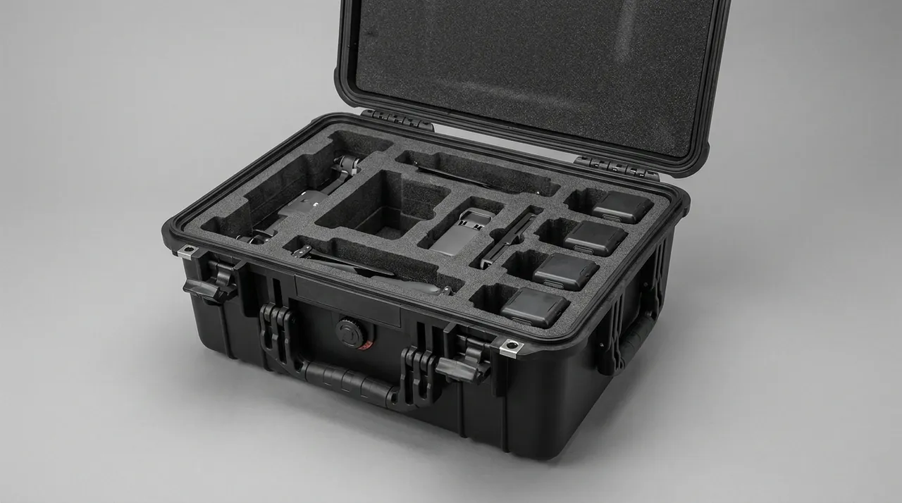
Head assembly: isolated cavity, three-point restraint, no over-constraint. The head should sit in its own cavity, restrained at three or four points to remove all translational freedom, while avoiding over-constraint, because over-constraint introduces assembly stress into the housing that can disturb internal phase relationships. Leave a 5 to 8 mm gap to the cavity wall and support with medium-to-low hardness EVA.
Needle bars: vertical single slots plus full-length sleeves. Needle bars should stand vertically or be carried on full-length supports, never with an unsupported mid-span. Fit a full-length soft sleeve to prevent surface scoring, and never let a needle bar share a cavity with a hard object.
Rotary hooks and bobbin cases: one per isolated cavity with pick-up tip sleeves. The pick-up tip is the most fragile geometric feature, so it needs a dedicated sleeve, and every hook must be separated individually with no stacking.
Take-up mechanisms and tension discs: compartments plus no sustained spring compression. A spring held under sustained compression undergoes stress relaxation, changing the tension setting. Packaging should therefore leave springs free or only lightly preloaded.
Ceramic thread guides: soft liners, no stacking. Ceramic parts are hard but brittle, and edge impact chips them. Use soft liners with one piece per compartment.
Guideways and carriages: full-length support, raceway guards, one per compartment. The raceway surface is a precision working face and must receive a soft guard bar and never contact a hard object. Carriages should remain on the guideway or be secured with a dedicated protective sleeve.
Embroidery frames and structures: forming support and diagonal restraint. Embroidery frames are thin-wall frame components with low torsional stiffness, so they need forming support and diagonal deformation restraint, with edge guards fitted. Selection of related cushioning and support materials is covered in cushioning liner materials and structure design.
Gasket design and case fit. Gasket compression ratio and material directly affect moisture control performance, and selection points are covered in protective case seal materials and gasket selection.
8. Protecting Feed Mechanisms, Frames and Guideways
The feed mechanism is the foundation of embroidery positioning accuracy, and its protection is often underestimated.
Guideway failure mechanism and protection. The raceway surface of a linear guideway is a precision-ground working face with extremely high roughness and straightness requirements. Any score generates impact and positional deviation as the carriage passes. Countermeasures include fitting a soft guard bar over the raceway, supporting the guideway at multiple points along its length to avoid self-weight bending, ensuring carriages do not detach or strike the ends in transit, and fitting end caps to prevent burrs.
Screw protection. Ball screw thread raceways are equally precision surfaces, and the nut contains recirculating balls. Transit must avoid axial shock on the screw, which can dent the raceway, avoid an unsupported mid-span that can cause bending, and avoid the nut running off the screw, which can spill the balls. A full-length sleeve plus at least three support points is recommended.
Timing belt protection. Timing belt pitch accuracy governs positioning accuracy. Three points matter: never bend the belt to a small diameter, with an empirical coiling diameter of at least 1.5 times the belt width and not less than the smallest pulley diameter; avoid oil and chemical contamination, since oil swells and deforms rubber; and avoid long-term compression, which permanently deforms belt teeth.
Stepper and servo motor protection. The shaft extension and encoder are sensitive locations. Fit a cover over the shaft extension to prevent impact and load, avoid shock on the encoder side, and place motors in isolated cavities with damping pads.
Embroidery frame and clamping mechanism protection. Frame straightness and flatness directly affect pattern distortion. Avoid stacking under load, use forming support with edge guards, and protect pneumatic or mechanical clamping faces with soft material while capping air ports.
Deformation prevention for welded structures. Large welded frame structures carry welding residual stress, and transit shock or uneven support can trigger stress release and deformation. Support points should be distributed sensibly and cantilever spans kept short.

9. Sealing and Ingress Protection: An IEC 60529 and GB/T 4208 View
Ingress protection is an important specification for embroidery parts cases, but it is important to understand what it does and does not prove.
IEC 60529 and GB/T 4208 are the same system. IEC 60529 and China's GB/T 4208 define identical IP code meanings: the first characteristic digit denotes protection against solid foreign objects and dust (0 to 6) and the second denotes protection against water (0 to 9). Common ratings for embroidery parts cases are as follows.
| Rating | Dust | Water | Meaning for embroidery components |
|---|---|---|---|
| --- | --- | --- | --- |
| IP54 | Limited dust protection | Splash resistant | Short in-plant transfers, dry environments |
| IP65 | Dust tight | Jet-water resistant | General inland transport and plant transfers |
| IP67 | Dust tight | Short immersion (1 m for 30 min) | Marine transport, rain and snow, wet handling |
| IP68 | Dust tight | Continuous immersion (per manufacturer) | Extreme duty, to be specified separately |
Three points must be clarified. First, an IP rating is neither a rust-prevention rating nor a guarantee of kinematic pair clearance protection. IP67 proves only that water cannot enter, yet moisture already inside the case, residual water on components, and moisture absorbed by the insert can still cause corrosion, so rust prevention must rely on the combination of drying, sealing, and desiccant. Second, IP ratings do not cover shock and vibration, which must be validated using ISTA or GB/T 4857. Third, a fully sealed case develops an internal-external pressure differential as temperature and barometric pressure change, which can make opening difficult or draw the gasket out of shape, so long sea and air routes normally justify a pressure equalisation valve, as discussed in protective case pressure equalisation valve function and selection.
The tension between sealing and venting. One frequently overlooked fact is that moisture inside a case must either escape or be absorbed. If components are sealed in before they are fully dry, the seal simply locks the moisture in. The process order must therefore be dry first, then seal, then add desiccant.
10. Moisture Control, Rust Prevention and Electronic Component Protection
Embroidery components include both precision steel parts and sensitive electronics, so the moisture strategy must serve both needs.
How humidity affects precision steel parts. Needle bars, rotary hooks, guideways, and screws have extremely low surface roughness and high specific surface area, so once a water film forms they corrode quickly. The corrosion products fill micro-clearances and also act as abrasive media, a double loss.
The critical relative humidity concept. For iron and steel there is a critical relative humidity, with an empirical value around 60 percent; below it, a continuous water film cannot form and the corrosion rate is very low. Keeping relative humidity inside the package below 40 percent is therefore the basic design target, and the humidity indicator card is the most economical means of verifying it.
A three-level moisture strategy. Level one is the component: clean and dry, apply rust-preventive oil or peelable film to metal parts, and avoid bare-hand contact with fit surfaces, since sweat is a strong electrolyte. Level two is the unit: seal individual pieces or groups into foil bags with desiccant and a humidity indicator card, vacuum or heat sealed. Level three is the case: gaskets plus a pressure equalisation valve plus slow-release desiccant.
Separate protection for electronic parts. Mainboards, encoders, and photoelectric sensors should follow the sequence of ESD bag first, then moisture barrier bag, then damped cavity. The ESD bag dissipates static and the barrier bag excludes water vapour; the two are not interchangeable.
Prohibited practices. Do not touch precision fit surfaces or grating surfaces with bare hands. Do not pack in rain or in high ambient humidity. Do not seal components that have not been dried. Do not mix stainless and carbon steel parts. Do not use sulphur-bearing rubber or low-grade regrind foam as insert material. Do not fill precision fit areas with cotton waste or felt.
11. Corrosion and Salt Spray Validation: An ISO 9227 Perspective
Embroidery components meet corrosive conditions both in the workshop and on the marine route, so salt spray testing is an important basis for validating corrosion protection.
ISO 9227 neutral salt spray (NSS). The standard specifies continuous spraying with a 5 percent sodium chloride solution at pH 6.5 to 7.2 and a chamber temperature of 35 degrees Celsius, with common durations of 24, 48, 96, 240, and 480 hours. Note that there is no simple conversion between salt spray duration and outdoor service life; the test is primarily used for relative comparison between candidate schemes and for consistency control.
Test subjects should be layered. Validate separately: the case metal hardware (hinges, latches, lifting points); the insert, gasket, and desiccant scheme; representative component samples such as a needle bar coupon, a rotary hook coupon, or a carbon steel fastener; and electrical assemblies packed according to the barrier bag scheme. Only layered data can localise the corrosion source.
Advanced methods. For export projects on tropical and oceanic routes, cyclic corrosion testing that alternates salt spray, drying, and humid phases reflects real atmospheric corrosion behaviour more closely than continuous salt spray.
Result criteria and contractual wording. Judgement is normally based on time to red rust appearance or on corrosion spot count and rating per unit area. The procurement agreement should specify the test method, duration, acceptance criteria, and disposition of non-conforming results rather than simply requiring that the product "shall pass a salt spray test".
12. Transport Vibration and Shock Validation: GB/T 4857 and ISTA
Micro-motion wear and phase drift cannot be judged by eye, so reproducible test methods are essential.
Validation baseline for embroidery-machine spares. Needle-bar straightness, rotary-hook pick-up and frame phase can drift with no visible sign, so the plan must pair GB/T 4857 vibration and impact with a before-and-after measurement of those items, sequenced by distribution environment via ISTA (Series 3 general simulation or Series 6 carrier-specific) or, for North-American orders, ASTM D4169 from the distribution cycle. The GB/T 4857, ISTA and ASTM D4169 guides are linked at the end of this article.
Baseline measurement before testing is mandatory. This is where embroidery components differ most from general equipment. Before testing, record needle bar straightness, rotary hook pick-up tip condition, head phase marking positions, guideway straightness, and frame diagonal difference. After testing, re-measure and compare against the baseline. A vibration test on embroidery components without before-and-after comparison data is almost meaningless.
Four checks that must follow testing. First, functional check: smoothness of manual head rotation, needle bar travel, rotary hook rotation, motor shaft rotation. Second, geometric check: needle bar straightness, guideway straightness, frame diagonal difference and flatness. Third, corrosion check: presence of condensate traces inside the package, humidity indicator card reading, and rust spots on metal surfaces. Fourth, cleanliness check: presence of debris and foreign objects in the insert and whether any component has shifted out of position.
Boundaries for using MIL-STD-810H. This standard is often cited to describe environmental test methods such as vibration, shock, temperature and humidity, and salt fog. It should be stated clearly that it is an environmental test methodology intended for verifying environmental adaptability of products and packaging, that it is not equivalent to military certification, and that it does not imply any military approval of the product. See MIL-STD-810H environmental testing and protective case compliance.
The cases described here serve only as outer transport packaging. They are not part of the equipment's own design or manufacturing, and do not alter the equipment's mechanical or process performance; safety and certification requirements for the equipment itself remain governed by the applicable regulations and standards.
Guide lube low-temperature viscosity and ceramic low-temperature brittleness. Heads for high-latitude or high-altitude destinations must cope with low-temperature brittleness and low air pressure; the guideway lubricant thickens at low temperature and raises drive resistance, while ceramic thread guides and sensor ceramics grow more brittle and can chip under impact. Both the guide lube's low-temperature viscosity and the ceramic parts' low-temperature brittleness must be assessed; see protective cases in extreme temperature environments.

13. Stacking, Handling and On-Site Unpacking Management
Stacking strength must be calculated for the worst case. The number of stacked layers inside a sea container is usually greater than for domestic transport, and the bottom case carries the upper load plus sustained vibration for a long period. Calculate bottom load as actual stacked layers multiplied by total unit weight multiplied by a safety factor of not less than 2, and mark the maximum stacking layers on the case.
Lifting and forklift practice. Heavy cases must be marked with lifting-point positions and permitted sling configurations (four-point or two-point), and single-point lifting and diagonal pulling are prohibited. Never sling embroidery frames or long guideways directly with wire rope; load must pass through case lifting points or dedicated lifting gear. Wheeled heavy-duty case selection is covered in protective case wheels and trolley handle structure.
Attitude and tilt indication. Head assemblies and embroidery frames have attitude requirements. Mark all four sides with up-arrow and do-not-invert symbols, and fit a tilt indicator for arrival assessment.
A six-step unpacking procedure. First, record case appearance and tilt-indicator status. Second, photograph the seal and labels. Third, read and record the humidity indicator card. Fourth, remove small parts and electrical parts before heads and long items. Fifth, check off the packing list item by item, inspect sleeves, plugs, and insert integrity, and confirm that no component has shifted. Sixth, check needle bar straightness and carry out a visual and dimensional check on guideways, and file the data.
The rust and dust clock after opening. Once a rust-preventive package is opened, protection begins to decay. Installation should be completed, or the parts transferred to controlled storage, as soon as possible after opening, rather than leaving them exposed to shop dust and humidity. If temporary storage is necessary, re-seal the package and replenish the desiccant.
The most common human-caused damage. On-site damage most often comes from unpacking and secondary handling: cutting deep into the insert cavity wall with a utility knife, laying a head on its side so the needle bar takes load, touching rotary hook pick-up tips and guideway raceways with bare fingers, putting a rotary hook down on a bench where it strikes other metal parts, and using the same gloves to handle precision parts and fasteners. These practices should be explicitly prohibited in the work instruction.
14. OEM/ODM Customization, Acceptance and Maintenance
A six-step customization process. First, requirement input: component list, 3D models or physical parts, weight and centre of gravity, transport route, environmental conditions, precision fit requirements, and cleanliness requirements. Second, scheme design: case structure, isolated cavity layout, restraint and cushioning scheme, and rust-prevention and moisture strategy. Third, prototyping: inserts are commonly produced by CNC-milled EVA or die-cut lamination, and prototyping verifies fit tolerance and ease of removal; process detail is covered in EVA foam insert custom process. Fourth, functional validation: sealing (IP rating), vibration and shock (ISTA or GB/T 4857), salt spray (ISO 9227), and before-and-after comparison of geometric quantities. Fifth, pilot batch and acceptance. Sixth, volume production and delivery.
Acceptance sampling method. For volume deliveries, AQL sampling acceptance is recommended, with inspection items and acceptance quality limits defined for appearance, dimensions, fit, sealing, marking, and desiccant provision; method and clause design are covered in custom case acceptance and AQL sampling plans. A material identification mechanism should also be established to prevent low-density regrind EVA being passed off as high-density EVA or ordinary PE being passed off as LLDPE; see how to identify genuine versus inferior protective cases.
Supplier selection and capacity assessment. The embroidery industry has many models and tight delivery windows, so a supplier's tooling response speed and batch consistency are critical; evaluation criteria are covered in how to choose a protective case OEM factory.
Maintenance and life management. Maintain a case register recording the date in service, number of trips, desiccant replacement history, gasket replacement interval, and insert replacement history; service life assessment is covered in protective case service life and reuse years. Divider reconfiguration is covered in protective case removable divider system.
JUNZHJIA engineering capability. JUNZHJIA, manufactured by Kexin New Materials (Guangdong) Co., Ltd., provides protective case customization for embroidery machine builders and for head and feed mechanism suppliers. The company can design isolated cavities, three-point restraint, and full-length needle bar sleeve inserts to suit specific head models, design one-piece-per-compartment and full-length support structures to suit rotary hook, guideway, and screw sizes, supply matched gaskets and pressure equalisation valves by model, provide test documentation for IP rating, vibration and shock, and salt spray projects, and support volume wholesale, agency, and OEM/ODM cooperation. For multi-model small-batch scenarios, a modular common shell with replaceable inserts keeps protection consistent while controlling tooling investment.
Frequently Asked Questions
Q: Why does an embroidery head lose phase alignment after transport, and how does packaging relate to it?
A: Phase misalignment means the relative timing between the head's kinematic chains, needle bar travel, needle bar swing, take-up lever, and rotary hook rotation, has shifted, showing up as a mismatch between needle and hook pick-up position, insufficient loop formation, and a higher thread break rate. Packaging relates to it directly for four reasons. First, over-constraint: if the insert applies hard restraint at many points, it introduces assembly stress into the housing, and slight housing deformation is amplified through the kinematic chains into phase offset. Second, vibration micro-motion: sustained micro-motion in transit accelerates wear of the kinematic pairs, and once fit clearances change, the phase relationship changes with them. Third, shock transmission: if the packaging does not isolate shock effectively, it passes through the housing to the most fragile kinematic pairs and causes local plastic deformation. Fourth, corrosion filling: corrosion products on fit surfaces change clearances and likewise offset phase. Prevention includes using three- or four-point restraint without over-constraint, leaving a 5 to 8 mm gap to the cavity wall and supporting with medium-to-low hardness EVA, using isolated cavities so the head shares no cavity with other parts, applying dry rust prevention, and recording phase marking positions before and after transport for comparison.
Q: Why do needle bars bend so easily, and how should they be packed?
A: A needle bar is a slender, small-diameter part with a high length-to-diameter ratio and low bending stiffness, a classic component that can bend under its own weight. Three common causes of bending are: an unsupported mid-span, where two-point support with too large a span allows self-weight plus vibration to produce long-term bending; compression at both ends, where the packaging presses the ends against hard surfaces and axial load causes buckling; and lateral impact, where collision with other components or the case wall produces local plastic bending. Five packaging points apply. First, stand the bar vertically or support it along its full length, never leaving an unsupported mid-span. Second, keep support spacing to an empirical maximum of one third of bar length. Third, fit a full-length soft sleeve to prevent surface scoring, but the sleeve must not apply clamping force. Fourth, never let a needle bar share a cavity with any hard object. Fifth, apply a thin rust-preventive oil film with desiccant to prevent corrosion of the fit surfaces. It is also advisable to measure straightness the same way before packing and after arrival, for example resting the bar in V-blocks with a dial indicator, to produce comparable data rather than relying on feel.
Q: How should rotary hooks and pick-up tips be packed to avoid damage?
A: The core principle is zero contact at the pick-up tip with one hook per cavity. The pick-up tip is the most precision-critical geometric feature on a rotary hook, with a very small tip radius; impact chips or rolls the tip, and such damage cannot be repaired on site, only replaced. Specific measures include: give every hook its own cavity and never place two or more in one compartment; fit a dedicated sleeve over the pick-up tip that covers it from outside without squeezing it inward; leave a 3 to 5 mm gap to the cavity wall and line it with low-hardness EVA or flocked fabric; never let a hook share a cavity with any metal item, especially small parts such as fasteners and pins; pack the bobbin case separately from the hook or secure each independently so relative movement cannot change the fit clearance; apply a thin rust-preventive oil film with desiccant and a humidity indicator card to prevent corrosion of fit surfaces and the tip; and never touch the pick-up tip or fit surfaces with bare hands when handling, since sweat is a strong electrolyte and leaves a corrosion initiation site.
Q: Why are feed mechanism guideways and screws so sensitive to impact?
A: Because they are surfaces-based precision parts, and their surface accuracy is measured in micrometres. The raceway surface of a linear guideway is precision ground with extremely high roughness and straightness requirements, and a carriage rolling on it is very sensitive to surface undulation. Once the raceway takes a score, every pass of the carriage generates impact and a resistance step, which translates directly into periodic positional deviation of the embroidery frame and appears as local pattern misalignment. Screws are more complex still: ball screw raceways are equally precision surfaces and the nut contains recirculating balls, so besides impact there are two specific risks, namely axial shock denting the raceway under the balls and the nut running off the screw in transit, which spills the balls and scraps the screw. Protection must therefore include fitting a soft guard bar over the raceway; supporting guideways and screws at multiple points along their length with spacing at an empirical maximum of one third of component length; fitting end caps to prevent burrs and impact damage; using dedicated protective sleeves to secure carriages and nuts against detachment and end impact; and never allowing these parts to share a cavity with hard items or to be stacked on each other.
Q: What protection rating should a parts case achieve? Is IP65 enough?
A: It depends on the transport route and the component type. IP65 means dust tight and jet-water resistant, adequate for general inland transport and plant transfers. IP67 means dust tight and able to withstand immersion in 1 metre of water for 30 minutes, and suits marine transport, rain and snow exposure, wet handling, and temporary open-air storage; IP67 is recommended for cases containing mainboards, encoders, and photoelectric sensors, and for cases of precision steel parts requiring long-duration rust protection. IP68 requires continuous immersion and is normally needed only in special duty. Three points must be emphasised. First, an IP rating is not a rust-prevention rating: IP67 proves only that water cannot enter, while moisture already inside the case can still cause corrosion, so rust prevention must rely on the combination of drying, sealing, and desiccant. Second, IP ratings do not cover mechanical shock and vibration, and vibration is precisely the main source of micro-motion wear in embroidery precision kinematic pairs, so strength must be validated by ISTA or GB/T 4857. Third, a fully sealed case develops an internal-external pressure differential as temperature and barometric pressure change, which can make opening difficult or draw the gasket out of shape, so long sea and air routes normally justify a pressure equalisation valve.
Q: Why is ISO 4406 used to describe the cleanliness of precision kinematic pairs?
A: Because ISO 4406 provides a general particle-count grading method that converts a vague notion of clean into comparable, contract-ready levels. The standard characterises cleanliness by the number of particles above a given size per unit volume of liquid, expressing the result as a three-part code for different size ranges. It was originally aimed at hydraulic oil cleanliness, but the methodology transfers directly: in the assembly and packaging of embroidery precision kinematic pairs, cleanliness level can be assessed by surface particle sampling or by sampling a cleaning fluid, and a limit can be written into the technical agreement. It matters particularly in this industry because kinematic pair failure is usually a combined action of micro-motion wear, corrosion, and contamination: vibration provides the micro-motion, humidity provides the corrosion, and contaminant particles act as abrasives between the fit surfaces, a hazard no less serious than the other two. The practical consequences for packaging are threefold: the packing area should be remote from cutting, grinding, and woodworking zones; there must be no wood shavings or foam debris inside the case; and insert materials should be low-outgassing and non-shedding. For high-precision heads, an assembly-environment particle concentration requirement can also be specified, with packaging treated as an extension of that environment.
Q: How can needle bars, rotary hooks and guideways be prevented from rusting during marine transport?
A: Four levels of measures should be combined: component, unit, case, and management. At component level, complete cleaning and drying before despatch, apply a thin rust-preventive oil film or peelable film to precision steel parts, avoid bare-hand contact with fit surfaces, and strictly separate stainless from carbon steel parts to prevent free-iron contamination. At unit level, seal individual pieces or groups into foil bags with desiccant and a humidity indicator card, vacuum or heat sealed, so that relative humidity at arrival stays below 40 percent. At case level, specify EPDM or silicone gaskets with a properly designed compression ratio, fit a pressure equalisation valve to balance the differential caused by day-night temperature swings, place slow-release desiccant inside, and raise case thermal resistance where necessary to reduce condensation. At management level, avoid placing cases directly against container walls and floors, avoid stowing alongside rusty metal or chemicals, minimise open-air waiting time, and unpack promptly on arrival to read the humidity indicator card and check for rust spots. Where corrosion performance is a firm requirement, specify the ISO 9227 neutral salt spray method, duration, and acceptance criteria in the procurement agreement.
Q: What information is needed to customise an embroidery machine parts case, and how is protection performance validated?
A: The recommended information set contains six items: a component list with 3D models in STEP, IGES, or native format; physical parts or photographs to check for differences from the model; weight and centre of gravity to determine support points and restraint direction; the transport route and environmental conditions, including transport mode, stacking layers, temperature and humidity range, transit duration, and whether the route is marine; precision and cleanliness requirements, including a list of critical fit surfaces, acceptable rust-preventive oil types, whether a cleanliness level is to be specified, the target IP rating, and whether salt spray and transport testing are needed; and marking and traceability requirements, including label content, language, coding rules, and accompanying documents. Protection performance is best validated through a closed loop of baseline measurement, testing, and comparison. Record needle bar straightness, rotary hook pick-up tip condition, head phase marking positions, guideway straightness, and frame diagonal difference before packing as the baseline. Carry out a vibration and shock test to ISTA or GB/T 4857. Re-measure the same parameters after unpacking and compare against the baseline. If the result is out of tolerance, analyse whether the cause is insufficient insert restraint, cavity over-constraint, excessive support spacing, or a stacking condition beyond the design assumption, and revise the scheme accordingly. This closed loop is the single biggest difference between validating packaging for embroidery components and validating packaging for general equipment.
Conclusion & Related Reading
The value of an embroidery machine parts case lies not in the case itself but in the four hidden risks it keeps away from the equipment: micro-motion wear, corrosion, impact, and thin-wall deformation. For embroidery machine builders and component suppliers, building a standard case series by head model and frame size and freezing isolated-cavity restraint and moisture-controlled rust prevention as standard tooling is a practical route to reducing both quality risk and storage cost. For apparel and home textile equipment buyers, specifying baseline geometric measurement, arrival re-measurement, humidity indicator card readings, and salt spray requirements in the procurement agreement is the most effective way to move thread-break-rate disputes forward into the contract stage.
Related Reading