

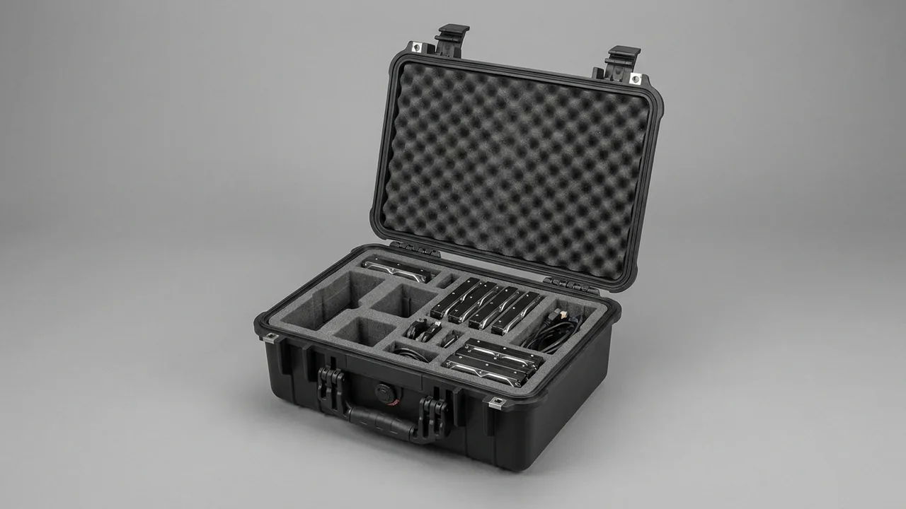
A piling rig case has to answer a harder question than whether a component fits. It has to answer whether the hammer body's mating faces, the drill tool joint threads, and the hydraulic power pack's internal galleries will still be in factory condition when the rig reaches the next pile position. Diesel hammer bodies and cushions, hydraulic hammer bodies and accumulators, power packs and cylinders, and drill tool joints are worth anywhere from tens of thousands to hundreds of thousands of yuan each, with assembly tolerances measured in microns, and yet they travel across the worst stretch of road on any project: washboard access tracks, mud spraying around the pile position, open storage yards exposed to alternating rain and night dew, and handling that depends on whatever crane or excavator happens to be free. The conclusion is unambiguous: piling rig components need a purpose-built case combining a heavy structural shell, compartmented moulded liners, independent lifting points, and IP67 sealing, with hydraulic parts controlled for both ISO 4406 cleanliness and internal dew point, because that is the only way to hold arrival rework rates down. The money saved by using ordinary timber crates or second-hand cartons is usually consumed in full by a single power pack flush or a single scrapped tool joint.
What makes pile-driving logistics genuinely difficult is that four awkward properties hold at the same time: the parts are heavy, expensive, oddly shaped, and sensitive to contamination. A heavy hammer body cannot simply nest in foam; the case structure must carry it. A cushion that absorbs moisture delaminates invisibly, and the loss is only discovered once it is installed on the mast and the blow energy no longer transfers correctly. A hydraulic component that ingests sandy slurry tends to reveal the problem during commissioning rather than on arrival, when valve spools begin to stick. A tool joint thread that has seen mud once will gall on make-up and condemn the whole joint. Worse, these components travel with the rig. A single road contract may involve thirty to eighty pile positions, so parts are packed, unpacked, and short-hauled repeatedly, and the case itself has to survive that cycle. This guide works through the protection logic component family by component family, covering case structure, liner selection, cleanliness and moisture control, heavy lifting and restraint, sealing class, and transport testing.
Table of Contents
- How Piling Rig Components Actually Fail in Transit
- Case Structure for Job-Site Vibration and Mud
- Load-Bearing and Wrapping for Diesel Hammer Bodies and Cushions
- Securing Hydraulic Hammer Bodies, Accumulators and Chisels
- Cleanliness and Moisture Control for Power Packs and Cylinders
- Preventing Kinks in Hydraulic Hoses and Couplings
- Thread and Taper Protection for Drill Tool Joints
- Liner Systems from Moulded EVA to Rigid PP
- Lifting and In-Case Restraint for Heavy Components
- Sealing Class and Mud-Water Exclusion
- Transport Testing and Compliance Basis
- Unpacking, Reassembly and Cleanliness Verification
- FAQ
- Conclusion and Further Reading
How Piling Rig Components Actually Fail in Transit
Piling equipment is rarely lost because something was dropped. Damage accumulates gradually through contamination, moisture uptake, and fretting until it crosses a threshold. Four failure modes cover almost every real case, and understanding them is the first step in selecting a case and the first test of whether a quotation is realistic. The first is mud and abrasive liquid ingress. Ground around a pile position is usually standing slurry, and during handling the base of the case can sit directly in it. Once sand grains lodge under a seal lip, liquid wicks past the compression face, and exposed hydraulic ports begin drawing in abrasive media. The second is displacement and mutual impact driven by vibration. Pile driving is itself a strong vibration source, road transport adds random excitation, and if components of very different mass share one cavity, the light part gets hammered by the heavy one. The third is secondary damage caused by missing lifting points, where a hammer body is slung with wire rope around the cylinder because no dedicated lug exists, leaving a groove that later becomes a stress raiser. The fourth is moisture uptake and condensation, because timber, carton board, and open-cell foam all absorb and release water, and diurnal temperature swings deposit condensation on internal surfaces, producing rust on steel and short-circuit risk in electrical enclosures.
Mapping those four modes onto specific parts produces a check list that can be used before a case design is approved.
| Component family | Dominant failure mode | In-case protection | Arrival check point |
|---|---|---|---|
| --- | --- | --- | --- |
| Diesel hammer body, anvil | Shell knocks, sling grooves | Steel bearers carry load, four-point sling sleeves | No grooves or burrs where slings contact |
| Hammer cushion, laminated rubber | Moisture delamination, compression set | Individually sealed bag with desiccant, stored flat | No bulging between laminations, even hardness |
| Hydraulic hammer body, accumulator | Pressurised part shocked, flange face dented | Precharge retained or released per maker, soft flange shields | Nitrogen pressure matches factory record |
| Chisel and connecting pins | Slender part bends, pins lost in transit | Multiple supports control deflection, pins and bushes compartmented as sets | Overall straightness within drawing limit |
| Hydraulic power pack, cylinders | Ports ingest dust, rod coating scored | Every port blanked or plugged, rod sleeve fitted | No missing blanks, no coating scratches |
| Hoses and couplings | Bend below minimum radius, thread damage | Coiled at large diameter, capped couplings in separate cells | No whitened creases in the outer cover |
| Drill tool joints, bits | Thread and taper ingest grit, galling | Thread protectors plus shaped taper nests | Threads spin freely by hand, no gritty feel |
| Control cabinets, sensors | Insulation resistance falls, connectors wet | Dedicated sealed cavity with desiccant, capped connectors | Humidity indicator card within limit |
Pile-driving work also means high turnover. A municipal foundation contract can run thirty to eighty positions, with components packed repeatedly as the rig advances. That makes latch, hinge, and gasket life far more important than it would be for one-way export packing, so suppliers should be asked for open-close cycle data and gasket replacement intervals. The reasoning used to compare structural hardware in toolbox hinge and latch sealing design applies directly here. Quarry and yard positions also bring heavy dust, so how easily the case shell and its seal groove can be cleaned deserves a place in the evaluation, as does the site practice described in quarry crusher component cases.
Case Structure for Job-Site Vibration and Mud
The structural design of a piling rig case has to satisfy two requirements that pull against each other: vibration resistance wants stiffness, mud exclusion wants sealing, and stiffness and sealing often interfere at the lid interface. Three dimensions matter: shell stiffness, seal groove geometry, and inertial restraint of the contents. Stiffness comes first. A heavy hammer body plus its bearer frame can weigh several times the empty case, so a thin flat base will deflect visibly when lifted from two points, and that deflection levers the seal face open. A load-bearing base should therefore be ribbed in both directions, and heavy-duty versions should have steel bearers moulded or bonded inside so the component load is passed into the side walls and pallet feet rather than resisted by a plastic floor in bending. Where stacking occurs, the top load should be checked using the static stacking method of GB/T 4857.3 so that lower cases are not crushed during ocean freight.
Seal groove geometry decides whether mud can actually be excluded. IP6X calls for complete dust tightness and IPX7 calls for no ingress after short immersion, but the water on a piling site is really a sand-laden slurry, and grains can sit on the compression face and open a leak path. A single flat compression strip is therefore weak in this duty. A stepped labyrinth groove combined with an O-ring is stronger: the outer groove acts as a sand trap with a relief step, the O-ring does the sealing, and the step between them gives grains somewhere to escape. As a rule of thumb the groove depth should exceed twice the gasket compression so that a trapped grain cannot hold the lip permanently open. The gasket compound must stay elastic across the site temperature range, which favours EPDM or silicone over ordinary PVC. Where day-night swings are large, the internal pressure of a sealed case cycles, and fitting a case pressure equalisation valve with a hydrophobic membrane lets the differential bleed off slowly rather than forcing the gasket open or drawing moist air in.
Inertial restraint is the third dimension. Vibration damages through acceleration rather than velocity, so the design aim is to deny a component the travel it needs to build speed. Three practical rules follow. First, each part sits in its own moulded pocket, with the walls touching but not preloaded. Second, any part above roughly 50 kg gets secondary restraint such as steel strapping or a clamping plate in addition to the liner. Third, components are not allowed to share a cavity along the load direction, so that a light part is never struck by a heavy neighbour. Amplitude is difficult to predict, so in practice restraint blocks are checked against a half-sine shock of roughly 10 to 20 g lasting 6 to 11 ms, then confirmed by a physical case test. Where a site shares a storage yard with concrete or asphalt plant, stacking and forklift compatibility also matter, and the pallet and fork-pocket approach in concrete batching plant component cases is a useful reference.
The reliable order of structural design is: define the load path first, then the lifting points, and only then the liner geometry. Treating foam as a structural member is the most common design error in piling rig cases.
Load-Bearing and Wrapping for Diesel Hammer Bodies and Cushions
A diesel hammer body concentrates mass in a large section while allowing no knocks on its machined surfaces. Cylinder, piston assembly, ram, and anvil are usually cast or forged and then machined, and the outer diameter and end faces often retain finish-machined bands. A single wire rope groove or a hard contact with a bearer is enough to require dressing or even scrapping. Packing therefore begins with the load interface: the body should sit on steel or dense hardwood bearers matched to the machining datums, with a low-hardness oil-resistant rubber pad bonded to the bearer face so contact stress stays below the yield limit. Axial freedom is removed by end stops, radial freedom by a curved saddle wrapping 90 to 120 degrees of the circumference, so the body cannot roll in transit.
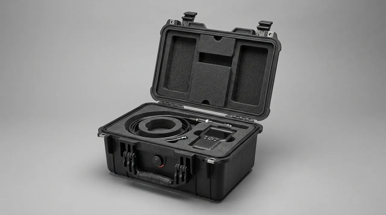
Lifting points must be designed as part of the case, not added afterwards. A body in the 3 to 15 tonne range is normally handled by a mobile crane on two or four slings, and if the case only has corner lugs while the component itself has no independent lifting provision, the component still has to be re-rigged after opening, which raises risk rather than lowering it. A workable arrangement is a pair of removable lugs on the bearer frame, so the packed assembly can still be lifted as a unit, with lug strength designed to a safety factor of at least four times the component weight. Sling sleeves are mandatory wherever a synthetic sling meets a machined edge. The figure below shows a hammer body seated on steel bearers with sleeves isolating the sling path.
Cushion protection follows the opposite logic to the body. A hammer cushion is laminated rubber, plywood, or a composite, and its job is to absorb impact and extend hammer life, which means its own worst enemies are moisture and sustained compression. Moisture hydrolyses the interlayer adhesive, the cushion delaminates, and the external dimensions barely change while the dynamic stiffness has already drifted, so the installed hammer transfers blow energy incorrectly. Cushions should therefore be vacuum sealed individually or wrapped in aluminium-laminate film with desiccant, stored flat, never stood on edge, and never stacked under heavy parts in a shared cavity. Where a project stores cushions inside the case for months, include a humidity indicator card and instruct the site to read the card before opening. When a body and cushion must ship in one case, split them vertically: the body occupies a load-bearing lower cavity and the cushion a separate sealed upper cavity, with a rigid divider breaking the vibration path between them.
Securing Hydraulic Hammer Bodies, Accumulators and Chisels
A hydraulic hammer is more complex than a diesel hammer, and the transport risk spreads across three items: the body, the accumulator, and the chisel. For the body, the critical features are the connection flange and the guide surfaces. Flange sealing faces are finely finished, and a dent will leak under high pressure, so flanges get soft shields with no hard contact against the sealing face. Guide surfaces run with small clearance to the wear plates, so they must never carry the support reaction; the load should go through the base or a dedicated support block, with guide faces oriented upward or sideways so that no debris can fall into the fit. Exposed oil and gas ports are blanked, and a plastic cap is added outside each blank so that handling cannot knock it loose.
The accumulator is a pressurised item and its transport state must follow the manufacturer's instruction exactly. Most hydraulic hammer accumulators leave the factory with a nitrogen precharge in the 100 to 160 bar region. Transport normally retains that precharge rather than venting it, because repeated charge and discharge cycles age the bladder, but retaining pressure means the case restraint must tolerate the additional load if the assembly is shocked. Accumulators should therefore be held in a wrap-around clamp or curved saddle that spreads load over the full cylindrical surface, never wedged by its two ends into a foam slot. Record the nitrogen pressure before dispatch and enclose the record with the case, then verify pressure again before lifting. If the accumulator is a removable type, ship it in a separate case from the body so that a heavy body cannot strike it over a bump.
The chisel is the item most easily ruined in transit. It is slender, and overall straightness is typically held to about one part in a thousand, so the inertial bending moment generated by a rough track can exceed the elastic limit and leave a permanent set. A bent chisel causes off-centre blows and accelerates wear in the guide bush. The answer is more support points rather than thicker foam: place a soft polyurethane V-block roughly every 1.2 to 1.5 m to control mid-span deflection, with the V locating the chisel against rolling. The shank and the bit end need their own shaped protection and must not share the same support as the shank body. Connecting pins and bushes are numerous, small, and easily lost at unpacking, so they belong in labelled cells as complete machine sets to prevent mismatching on site. Where undercarriage parts ship in the same consignment, the zoning approach described in hydraulic lift component cases transfers well.
Cleanliness and Moisture Control for Power Packs and Cylinders
Protecting hydraulic components in transit is fundamentally a cleanliness campaign. Piling hydraulic systems run at high pressure with small spool clearances and are highly sensitive to fluid contamination. ISO 4406 expresses contamination as three numbers covering particles larger than 4, 6, and 14 micrometres per millilitre, and hydraulic hammer makers commonly demand a system level of 17/15/12 or cleaner, with power packs leaving the factory around 18/16/13. The danger in transport is that a single journey with open ports can set cleanliness back by two grades. Dust, sand, liner debris, and corrosion particles produced by condensation all enter the system at reassembly, showing up as sticking spools, sluggish servo response, and cylinder creep. Hydraulic packing must therefore achieve two things at once: every port closed, and no liner material that sheds.
The port closure standard is specific. Every oil, gas, and test port gets a blank or plug matched to the thread form, with a plastic cap outside it. Flanged connections get a cover plate with an O-ring, fastened with bolts. Couplings get threaded plugs, not merely a plastic bag slipped over the end. Before closing anything, confirm no residual oil is dripping, because a drip will collect airborne dust. Shedding control is the overlooked half: ordinary open-cell foam and low-density pearl foam break down under vibration, and while the debris lands outside the blank, it is easily carried into the system by hand at reassembly. Hydraulic cavities should use closed-cell PE, IXPE, or a low-outgassing moulded EVA, and paper buffers and adhesive tape should be kept out of them entirely.
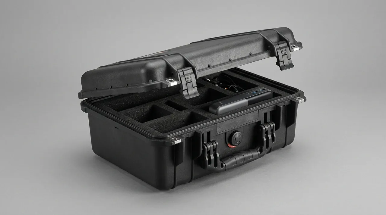
Moisture control matters as much as cleanliness, because corrosion is itself a particle source. The practical targets are a relative humidity inside the sealed cavity held below 40 percent, or an internal dew point at least 5 to 10 K below the lowest expected ambient temperature. Three measures work together. First, choose low-absorption liner materials and keep timber and large areas of board out of sealed cavities. Second, dose desiccant against the free volume, typically 1 to 2 kg of molecular sieve or silica gel per cubic metre, taking the upper figure in humid regions. Third, include a humidity indicator card with a written arrival procedure so the site reads the card before opening. Components stored outdoors for weeks through the wet season benefit from a replaceable desiccant cartridge and a viewing window, because the alternative is opening the case repeatedly to check, which is itself a moisture source. Cylinders carry one extra rule: an extended piston rod must be sleeved, because the rod is chrome or ceramic coated and a scratch allows corrosion to creep along the coating interface, costing far more to repair than a sleeve costs to fit. Where the rod cannot be retracted, the sleeve bore should be 3 to 5 mm larger than the rod with a soft inner liner, secured at both ends with ties that do not pinch the rod.
Preventing Kinks in Hydraulic Hoses and Couplings
Hydraulic hoses are the quiet casualties of transport. When the outer cover shows a whitened crease, the wire reinforcement beneath is usually already locally damaged, yet the hose looks serviceable and may not burst until hundreds of operating hours later. Bend radius is the governing factor. Every hose size has a minimum bend radius, and as a rule of thumb a medium or high pressure hose tolerates roughly 6 to 9 times its outside diameter, though the maker's catalogue value always governs. Any point bent tighter than that damages the reinforcement. Hoses therefore must not be looped tightly like electrical cable but coiled to a diameter of at least twice the minimum bend radius, then secured with two ties so the coil cannot spring open.
Coupling protection is the other half of the job. Piling hoses mostly terminate in SAE flange, JIC, or BSP threaded couplings, and a dented sealing face will leak. Practical measures include one coupling pair per compartment, coupling ends facing down or sideways with protective caps fitted, and corrugated plastic sleeve over the coupling area for bulk hose sets. Hoses and couplings should not share a cavity with hammer bodies or power packs, because movement of a heavy part will crush a coil directly. Where a hose set must travel with a cylinder, put the hose cavity above the heavy parts and separate the two with a rigid divider. Once packed, mark the case with a handling instruction consistent with GB/T 191 pictorial marking practice, covering orientation limits and the location of the hose cavity.
A common site shortcut is to stuff hoses into whatever void remains in the case. A hose is neither a cushioning material nor a component that should carry compressive load from its neighbours.
The order in which hose sets are retrieved also deserves design attention. Pile sites frequently need one hose replaced, and if the whole set is bundled together, retrieval means disturbing everything, which increases the chance of damage. Group hoses by function, coil each group separately, and label them, for example main hammer supply, return, and pilot lines. The site can then take one group without touching the rest, and the risk of cross-connection at reassembly falls sharply.
Thread and Taper Protection for Drill Tool Joints
Drill tool joints include drill pipe joints, down-the-hole hammer joints, auger connection sections, and casing joints. What they share is a mating system combining a precision thread with a taper, and both features have essentially zero tolerance for grit. Once sand has entered a thread, make-up presses grains between the flanks and generates local high spots; the result ranges from abnormal torque to torn and seized threads and a scrapped joint. A taper, whether a cone or a socket, that has been dented by a hard object loses contact ratio, which compromises both sealing and load transfer. Tool joint packing therefore belongs in the precision packaging category, with a higher standard than general machined parts.
Three layers of protection apply. The first is a thread protector matched to the thread form and pitch, in plastic or steel, long enough to cover the whole threaded length with a small overhang that acts as a sacrificial bumper. Wrapping in tape is not a substitute, because the adhesive residue holds grit and makes cleaning harder. The second is a shaped taper nest: the moulded liner should include a cone of matching angle so the taper rests in contact rather than hanging free, with a lint-free cloth or low-outgassing film between taper and nest. The third is one joint per pocket. Joints must never be stacked, and in particular no taper may touch a thread. For long drill pipe or casing, support every 1.5 m or closer to control deflection, following the same logic as chisel support but at tighter pitch because thin-wall pipe has lower bending stiffness.
Unpacking and reassembly need controls too. When a crane or excavator lifts a tool joint on site, the rigging must not touch the threaded section. Before make-up, clean the threads with solvent and a purpose-made brush, then apply thread compound matched to the duty; one function of that compound is to isolate grit and water. In dusty locations, give each joint set a reusable sealed protector, collect it at unpacking, and refit it before reassembly so the loop closes. When tool joints ship with hydraulic power packs, keep them in separate cases or at least separate cavities, because a blank or plug that works loose from a power pack becomes a loose hard object that can dent a thread section.
Liner Systems from Moulded EVA to Rigid PP
The liner is the part of a piling rig case most often improvised, yet it determines how components are supported, how clean they stay, and how quickly they can be retrieved. A liner must deliver four things: shaped location, vibration damping, a material that neither absorbs water nor sheds particles, and enough durability for repeated handling. Different components weight those four differently, so a professional solution is rarely one foam throughout the case but a zoned selection. The table below sets out the practical fit for each material.
| Liner material | Forming method | Damping and recovery | Suited piling components | Cautions |
|---|---|---|---|---|
| --- | --- | --- | --- | --- |
| Moulded EVA | CNC carved or hot pressed | Good recovery, repeated handling | Power packs, cylinders, joints, chisels | Specify low-outgassing grade to avoid plasticiser migration |
| Cross-linked IXPE | Hot pressed | Very low water uptake, weather resistant | Cushions in long storage, sensor cavities | Relatively stiff, heavy parts need a soft interface pad |
| Closed-cell PE | Cut or hot pressed | Low water uptake, low shedding | Hydraulic cavities, control cavities | Weak damping, unsuitable as a load-bearing layer |
| Rigid PP dividers | Injection moulded or machined | Stiff, no shedding | Cavity separation, heavy-part stops | Faces touching components need soft pads |
| Polyurethane blocks | Cast or moulded | High compressive capacity, abrasion resistant | Hammer body saddles, chisel V-blocks | Density must match the load or the block collapses |
| Ordinary pearl foam and sponge | Cut | Moderate recovery, friable | Outer void fill for non-precision items only | Never in hydraulic, thread, or taper cavities |
Layout follows material selection. Three rules apply to piling cases: heavy parts low and near the centre, long parts along the long axis, precision parts in independent cavities. Keeping heavy mass low and central puts the centre of gravity near the base centre so a four-point lift stays level. Running long parts along the long axis keeps the case narrow and makes forklift handling easier. Independent cavities for precision parts are the basic requirement for preventing cross-contamination. Pocket walls should carry a 3 to 7 degree draft, which eases insertion and removal and keeps parts moving freely even when slightly swollen or coated in preservative. Where in-service and spare parts must be distinguished, colour-coded or numbered pockets linked to a case manifest give traceable control.
When component models change from project to project, replaceable liners matter more than a one-off optimum. A common engineering approach keeps the shell and the rigid divider skeleton and changes only the moulded liner modules, so one batch of cases serves several rig types and the amortised cost per part falls significantly. The cost structure of tooling versus liner modules is set out in custom case mould cost analysis, and where shapes are complex enough to need trial fitting, EVA foam insert custom process describes a sensible sampling and acceptance rhythm. For comparing foam options line by line, protective case foam material comparison provides the metrics that a selection meeting needs. JUNZHIJIA normally groups piling components by family, drafts a liner layout for each group, then checks the load path against the principle of structural load-bearing for heavy items and isolation for precision items before fixing case dimensions and lug positions. Working in that order removes most late changes, and the compartment logic itself follows the guidance in custom foam inserts guide.
Lifting and In-Case Restraint for Heavy Components
Lifting design is where risk concentrates in a piling rig case, because a failed lifting point costs not only the component but also site safety. Three principles cover it: independent lifting provision, a controlled path, and secondary restraint. Independent lifting provision means a heavy component has its own lug or lifting eye rather than relying on the case lugs to carry it indirectly. A controlled path means no lift ever requires the component to pass through an uncontrolled attitude such as a diagonal drag or an underslung pull. Secondary restraint means that after the part is seated, steel strapping, clamping plates, or bolted clamps secure it so inertial loads travel through structure rather than foam.
Strap angle needs controlling. Inertial load generates a tangential component in a strap, and the smaller the angle between strap and component surface, the more easily it slides. As a rule the angle should stay within 45 degrees, with edge protectors at each turn so the strap neither cuts soft material nor marks the component. Strap capacity should be selected against a recognised system such as EN 12195-2 lashing capability, with the stated lashing capacity covering the calculated inertial force plus margin. A 500 daN class tensioner is a sensible single-strap choice for a one tonne component on normal road transport, but rail or long ocean legs raise the requirement and need separate calculation. Bolted clamps suit components with mounting holes: check plate thickness in bending, use bolts of grade 8.8 or better, and re-verify torque after the load is applied.
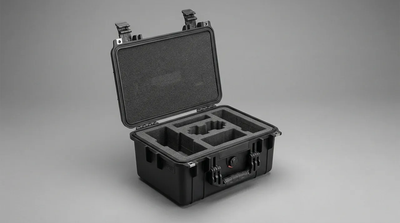
Restraint blocks belong in pairs along the principal inertial axes. On road transport the dominant accelerations are longitudinal and vertical, with lateral acceleration smaller but not negligible, while sea freight adds significant roll acceleration. Blocks should therefore be fitted on all four sides, with 2 to 3 mm assembly clearance for seating filled by soft shims. Case lifting itself needs a written procedure: mark the centre of gravity, specify sling length and angle limits, and prohibit single-point lifting of a loaded heavy case. Where a case shares a hold or wagon with precast concrete elements or reinforcement cages, rigid stacking corners that allow two loaded cases to be stacked while preserving fork access are worth specifying, following the load marking practice in hoist component cases.
Sealing Class and Mud-Water Exclusion
Sealing class should follow the real duty rather than a wish for the highest number. The typical duty for a piling rig case is short-term immersion, continuous mud spray, and occasional high-pressure washing, so the sensible combination is IP6X dust tightness with IPX7 short-term immersion, plus IPX6K high-pressure jet capability where a pressure washer is used on the shell. IP ratings are defined in IEC 60529 and GB/T 4208; IPX7 covers 30 minutes at 1 m depth, which matches standing water on site, while IPX6K belongs to ISO 20653 and better represents washdown. One common misunderstanding is worth stating plainly: IP67 does not imply resistance to prolonged immersion, and it says nothing about abrasive ingress, so gasket life in a mud environment depends on wear resistance and extrusion resistance.
Gaskets fail along three typical routes: sand grains bedding under the lip, low-temperature hardening that removes recovery, and uneven compression caused by lid distortion. The countermeasures are a labyrinth groove with a sand relief step, an EPDM or silicone compound with good low-temperature behaviour, and a lid stiff enough plus latches spaced closely enough to keep compression uniform. Latch count and pitch must be calculated, and longer cases need more of them so that the middle of a long side cannot lift. Gasket replacement intervals belong in the user manual; on a piling site a quarterly inspection is realistic, with replacement whenever a permanent compression set or surface cracking appears. For a comparison of sealing compounds in wet, oily, and abrasive service see protective case seal material selection, for how sealing and cushioning interact see cushion and seal shock design, and for the acceptance details of IP testing see IP67 protective case requirements. No unreachable low point should exist inside the shell; a drain plug belongs at the lowest point, and the seal groove should be wiped clean before every repack.
Transport Testing and Compliance Basis
The value of transport testing is that it converts a vague risk of damage into a defined condition, giving the case design a quantitative basis. For piling components the relevant categories are vibration, impact and drop, stacking, and temperature-humidity cycling, addressed by the GB/T 4857 series, the ISTA protocols, and ASTM D4169. One clarification matters commercially: environmental test method standards such as MIL-STD-810H may be used as a reference for defining vibration spectra, temperature ranges, and humidity profiles, but this does not constitute any military certification and must never be described as such in commercial documents.
| Test or method | Typical application | Key parameters | Pass criteria |
|---|---|---|---|
| --- | --- | --- | --- |
| GB/T 4857.23 random vibration | Road and rail simulation | PSD from route spectrum, commonly 0.5 to 2 h | No component shift, no liner powdering, seals intact |
| GB/T 4857.3 static stacking | Warehouse and sea stacking | Load derived from stack height | No shell buckling, no base deformation |
| GB/T 4857.5 drop | Manual handling impacts | Drop height selected by mass | Component functions normally, no lug cracking |
| ISTA 3E unitised loads | Palletised consignments | Incline impact, random vibration, rotational drop | Pallet to case connection intact |
| ASTM D4169 distribution cycle | Full export route | Test sequence from chosen DC | Every element passed, no water traces |
| IEC 60529 / GB/T 4208 | Sealing verification | IPX7 immersion, 1 m for 30 min | No internal water traces, card within limit |
The test case should carry real or mass-equivalent dummy components, with accelerometers and witness marks on critical surfaces so the source of any displacement can be located. After the run, functional checks are not enough: inspect the seal groove for embedded sand, the liner for powdering, and the fasteners for loss of preload. For the practical running order of a test programme see ISTA transport testing procedure, for building sequences from distribution cycles see ASTM D4169 distribution cycle testing, and for domestic acceptance mapping see GB/T 4857 transport packaging testing. Export consignments should also carry marking complying with GB/T 191 and GB/T 13384.
Unpacking, Reassembly and Cleanliness Verification
Even a well-built case loses its value if unpacking and reassembly follow no procedure. The recommended sequence for piling components is record, read, separate, verify. Record means photographing the shell, seal condition, and lifting points before opening, checking for impact marks or a tripped tilt indicator. Read means checking the humidity card and shock indicators before deciding to open, and moving components to a dry area first if humidity is over limit. Separate means placing precision items and heavy items in distinct areas after opening and returning thread protectors, blanks, and plugs to their numbered positions rather than piling them together. Verify means sampling hydraulic fluid for contamination level, spinning tool joint threads by hand, and inspecting piston rod coatings.
Cleanliness verification is specific and repeatable. Before reassembly, draw a sample from the power pack reservoir or a cylinder return port and read the ISO 4406 code against the factory record. If the code has dropped by more than one grade, investigate whether a blank was missing, liner debris entered, or condensation produced corrosion, then flush before commissioning. Clean liners with a neutral detergent and a soft cloth, never a solvent that leaves residue able to emulsify with hydraulic fluid. For the shell itself, the steps in how to clean a protective case apply, with attention to groove clearance, drain plug flow, and whether the gasket needs a light silicone film after washing to keep its elasticity.
Long-term storage needs one additional arrangement: inspect every three to six months, or read internal humidity through a window and replace desiccant. Pile-driving projects frequently hold components for six months before mobilising, and that dormant period is no safer than the journey, particularly through a humid monsoon season when liner absorption can pit metal surfaces. Putting the inspection interval into the equipment register costs far less than remedial work later.
FAQ
Q: Should a piling rig case be sized first, or should the liner design come first?
A: The support and restraint scheme should come first, and case dimensions follow from it. Component failures in piling work are driven mainly by relative movement and contamination ingress; the support method sets the movement, and whether separate cavities are needed sets the contamination control. The correct order is to list the weight, envelope, centre of gravity, and critical mating features of every component family, then define the load-bearing interface and restraint axes for each item, then decide which items need independent cavities, and only then derive case length, width, height, and lug positions. Buying a shell first and filling it with foam afterwards usually produces a case that is big enough but has no valid load path, so the heaviest body ends up sitting on foam, the liner collapses over a rough track, and the component sinks until it contacts the case wall. A useful compromise is to fix the shell structural series from the largest and heaviest item, then design modular liner inserts within a few sizes of that series, which preserves both a valid load path and the option to reuse shells on later contracts.
Q: A hammer cushion looks like a simple block of rubber, so why does it need stricter packing than the hammer body?
A: Because damage to a body is visible while damage to a cushion is not. The cushion absorbs blow impact and protects the hammer and the pile cap, and its performance depends on the laminated structure and the dynamic stiffness of the compound. Moisture hydrolyses the interlayer adhesive and produces delamination that is difficult to see; external dimensions barely change while the dynamic stiffness and damping have already drifted, which shows up as abnormal energy transfer and reduced hammer life. Sustained compression also creates permanent set, reducing effective cushion thickness. The cushion should therefore be vacuum or foil sealed individually with desiccant, stored flat, never stood on edge, and never placed in the same cavity as a heavy part. Where a project stores cushions for extended periods, include a humidity indicator card and require the site to read it before installing. Treating a hammer cushion as an ordinary rubber part is one of the more expensive mistakes in pile-driving logistics, because the failure appears only in service.
Q: What cleanliness level must a hydraulic power pack reach for transport to be acceptable?
A: ISO 4406 expresses contamination as a three-number code, and hydraulic hammer makers commonly require a system level of 17/15/12 or cleaner, while power packs typically leave the factory near 18/16/13. The transport objective is that cleanliness does not regress, not that transport improves it. Acceptance should therefore be based on the factory record with a permitted deviation of no more than one grade. Three actions achieve that: blank or plug every port with a correctly matched fitting and secure flanged connections with an O-ring cover plate and bolts; use closed-cell PE, IXPE, or a low-outgassing moulded EVA inside hydraulic cavities and keep paper and tape out of them; and hold internal humidity below 40 percent relative humidity or keep the internal dew point 5 to 10 K below the lowest expected ambient temperature. On arrival, draw a sample and read the code. If cleanliness has regressed by more than one grade, flush before commissioning and audit the closure and desiccant records to find out why.
Q: Can an accumulator and a chisel travel in the same case as the hammer body?
A: Sharing one case is normally unwise, and sharing one cavity should be avoided entirely. An accumulator is a pressurised item whose transport state must follow the manufacturer's instruction, and precharge is usually retained to avoid ageing the bladder through repeated charge cycles, which means the restraint must tolerate the additional load generated by a shock and should use a wrap-around clamp or curved saddle spreading load over the cylindrical surface. If the accumulator shares a cavity with a heavy body, movement of that body over a bump will strike it, and the risk cannot be controlled. The chisel has a similar problem from a different direction: it is slender, its straightness is typically held to about one part in a thousand, and it needs V-block support roughly every 1.2 to 1.5 m to control deflection, which conflicts directly with the bearer layout needed by the body. The robust arrangement gives the body, the accumulator, and the chisel physically separated cavities, or ships them in separate cases. If transport capacity forces a single case, put the heavy body in the lower load-bearing cavity and the chisel in an independent long upper cavity separated by a rigid divider.
Q: Why is tape not an acceptable substitute for a thread protector on drill tool joints?
A: Because adhesive residue becomes a carrier for grit. The failure mechanism in a threaded joint is grit pressed between the flanks, creating local high spots that tear the thread form or seize the connection. Tape does not fill the thread roots and does not conform continuously to the flanks, so grains still enter. More importantly, tape leaves residue when it is removed, and that residue is tacky enough to hold sand and dust firmly, so cleaning before make-up requires repeated solvent wiping that itself introduces handling risk. The professional method is a plastic or steel thread protector matched to the thread form and pitch, covering the full threaded length with a small sacrificial overhang to absorb impacts. Tapers need their own solution: a nest of matching cone angle inside the moulded liner so the taper rests in contact rather than hanging unsupported, with a lint-free cloth between surfaces. Recover protectors at unpacking and refit them before reassembly, cleaning the threads and applying matching thread compound first.
Q: What do restraint blocks and straps each contribute to securing a heavy hammer body?
A: They address different load directions and cannot substitute for one another. Restraint blocks control travel, holding the component in a position where it cannot accumulate velocity, and they primarily resist horizontal acceleration, so they belong in pairs along the principal inertial axes with 2 to 3 mm assembly clearance filled by soft shims. Straps control lift-off, because a bump generates an upward inertial force, and with stops alone a body can rise and land again, producing local impact marks. Strap angles should stay within 45 degrees with edge protectors at each turn so the strap neither cuts soft material nor marks the part, and capacity should be selected from a recognised lashing capability system with margin. For components with mounting holes, bolted clamps are often more reliable than straps, using bolts of grade 8.8 or better with torque re-verified after loading. Combining all three methods according to the characteristics of each component is what makes a complete restraint scheme.
Q: If a case is rated IP67, is it safe to leave it standing in site water all day?
A: That is not what the rating means. IPX7 covers 30 minutes at 1 m depth with no ingress, and it says nothing about prolonged immersion. More importantly, the water on a piling site is a sand-laden slurry: grains lodge on the gasket compression face, open leak paths, and abrade the lip, and this abrasive ingress duty is harsher than clean-water immersion, so long exposure shortens gasket life noticeably. Where standing water or pressure washing is routine, specify IPX6K jet resistance, design the seal as a labyrinth with a sand relief step combined with an O-ring, ensure a drain plug at the lowest internal point, and space latches evenly to keep compression uniform. In service, put the gasket on an inspection schedule and replace it as soon as a permanent compression set or surface cracking appears, applying a light silicone film after washing. Treating IP67 as a submersible rating is a very common root cause in seal failure complaints.
Q: How should the service life of a case be assessed when components are cycled dozens of times on site?
A: The question is not whether the case survives one journey but how long its structural and sealing parts last under fatigue. Ask suppliers for three sets of data: rated open-close cycles for latches and hinges, compression set figures for the gasket at normal and low temperature, and long-term deflection under stacking load. Real site duty also includes abrasion from mud and exposure to ultraviolet light, so exposed metal parts need corrosion protection and the shell compound needs a weather-resistant grade. Keep a register: check lugs and latches weekly, gaskets quarterly, and base deformation at each project milestone. Where one batch of cases must serve several rig types, keep the rigid skeleton and change only the moulded liner modules, which reduces the amortised cost per component. When comparing structural hardware, the approach in toolbox hinge and latch sealing design helps separate the ability to open from the ability to keep opening. Ask for open-close cycle data in writing before a structure is specified.
Conclusion and Further Reading
Give the weight to structure, the movement to stops, the precision to isolation, and keep grit outside the seal. Bodies and cushions concern load path; power packs concern cleanliness and dew point. JUNZHIJIA supplies custom liners, matched seals, and OEM or ODM production.
Related Reading