

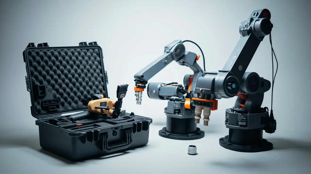
End effectors are the smallest, most expensive and most precision-sensitive components in an industrial robot system. A servo electric gripper, a tool changer or a six-axis force sensor often accounts for 10 to 25 percent of total system cost, and their precision datum faces, including flange faces, coupling faces and guide rail surfaces, carry tolerances in the 0.01 to 0.05 mm range. A single apparently minor knock in transit, or just 2 mm of movement inside the case, can degrade a tool changer's repeatability from plus or minus 0.02 mm to worse than plus or minus 0.1 mm, shift a force sensor zero by several newtons, or leave irreversible brinelling marks on gripper guide rails. The correct approach is to treat an end effector as a precision measuring instrument rather than a mechanical part: use a contour-fitted liner for zero-clearance restraint, relieve or softly contact every precision datum face, isolate heavy items from precision items in separate compartments, and include desiccant and corrosion protection for high-humidity ocean freight. This article is written for robot integrators, end-of-arm tooling manufacturers and overseas channels, and provides liner construction, sealing classes, test criteria and acceptance methods that can be applied directly.
In practice, disputes over end-effector deliveries cluster in three places. First, a gripper is installed and its gripping position is offset, and even after re-teaching it remains unstable, and teardown reveals micro-plastic deformation of a rail or rack from impact in transit. Second, a tool changer fails repeatability acceptance, traced back to the changer body having collided with another metal item inside the case. Third, a six-axis force sensor zero drifts beyond tolerance, and the drift is irreversible so the unit must go back to the factory. What these three share is that the damage occurs on a precision datum face and in most cases cannot be repaired on site. And they usually trace back to the same packaging decision: using a generic foam case on the principle that it fits, so it is fine. This article splits end effectors into pneumatic grippers, electric grippers, tool changers, force and tactile sensors, vacuum cups and end-of-arm tooling, and gives the packaging construction, relief requirements and acceptance criteria for each. It also explains what JUNZHJIA can deliver in custom liners and OEM/ODM case development.
Table of Contents
- 1. Why end effectors are the most expensive small items
- 2. Protection differences and conflicts across six end-effector families
- 3. Tool changer precision datums and force analysis
- 4. Pneumatic grippers: rails, racks and air port protection
- 5. Electric and servo grippers: encoders, limits and internal batteries
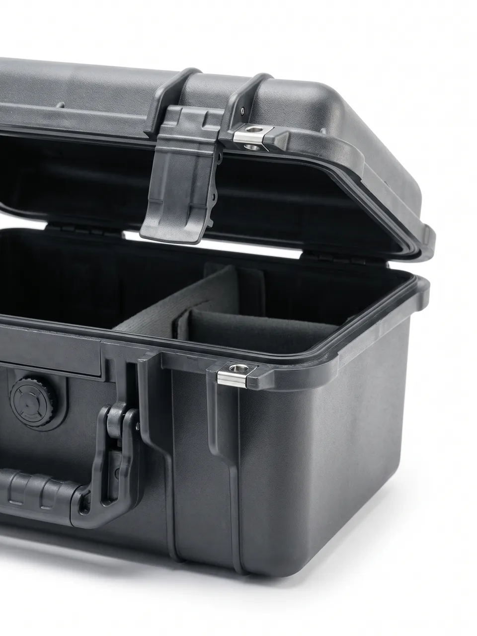
- 6. Zero-point protection for force, torque and tactile sensors
- 7. Vacuum cups, end-of-arm tooling and cable assemblies
- 8. Liner design: contour fitting, relief and quick access
- 9. Sealing, moisture and corrosion: IEC 60529, GB/T 4208, IP65 and IP67
- 10. Vibration and shock control: from transport spectra to liner stiffness matching
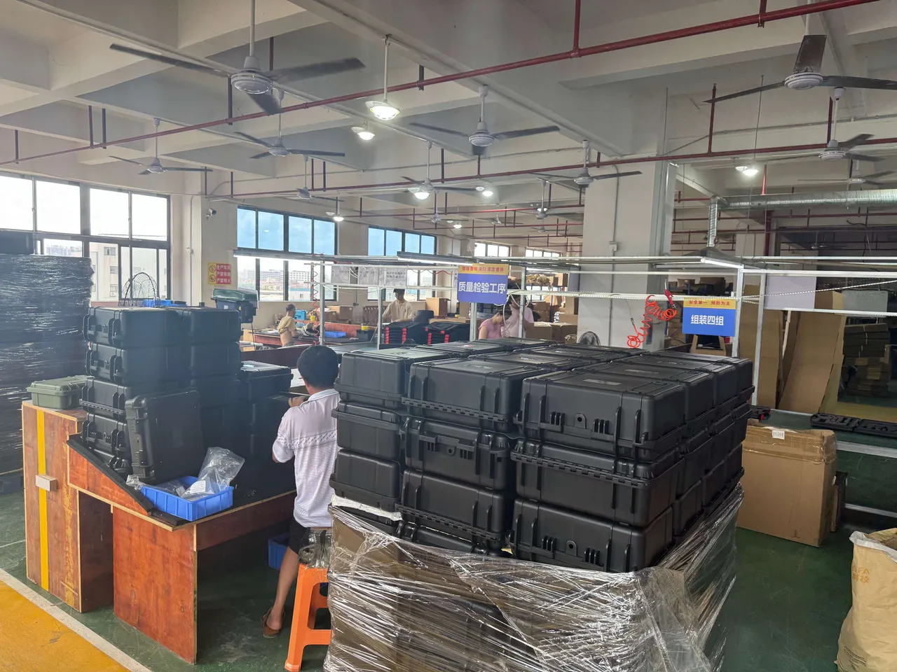
- 11. Transport test references: ISTA, GB/T 4857, ASTM D4169 and MIL-STD-810H
- 12. Materials, flammability (UL94) and marking compliance
- 13. Customization workflow, delivery documents and acceptance (AQL)
- 14. Frequently Asked Questions
- 15. Conclusion and Related Reading
1. Why end effectors are the most expensive small items
End effectors have extremely high value density. In a typical combination, a 6-axis industrial robot body might be worth a mid five-figure sum, while the matching servo electric gripper, tool changer and six-axis force sensor together can account for 15 to 25 percent of total system cost, even though their volume may be one percent of the robot. That combination of high value, small volume and high precision means the packaging logic is completely different from a robot body.
Three key differences:
Difference one: precision datum faces must never contact hard objects. End-effector precision comes from specific datum faces: the mounting face that connects to the robot flange, commonly an ISO 9409-1 circular flange with locating pin holes and threaded holes; the locking face of a tool changer; the mounting face of gripper guide rails; and the load-bearing face of a force sensor. Flatness and surface roughness requirements on these faces are extreme, and any hard contact or trapped particle transfers directly into precision loss.
Difference two: relative precision between components matters more than individual precision. A tool changer's repeatability is the coupled result of the master-side plate and the tool-side plate. If the two plates take different impacts in transit, accuracy after coupling can fall outside tolerance even when each looks intact. Plates shipped as a pair should therefore be secured in the same liner module so their relative position stays stable.
Difference three: most damage is irreversible and cannot be repaired in the field. Rail brinelling, micro-deformation of a rack, force sensor zero drift and permanently flattened seals cannot be compensated by re-teaching or parameter changes. They require a factory return or replacement, and the logistics and downtime cost usually far exceeds the price of the end effector itself.
Conclusion: the design priority order for an end-effector case should be precision datum protection first, then zero-clearance restraint, then moisture and corrosion control, then drop resistance, then appearance. A supplier that puts drop resistance first tends to produce a case that is thick but lets the contents move.
2. Protection differences and conflicts across six end-effector families
| Component family | Typical weight | Critical precision areas | Protection priorities | Recommended sealing class |
|---|---|---|---|---|
| --- | --- | --- | --- | --- |
| Pneumatic gripper, parallel, angular or three-jaw | 0.3 to 5 kg | Rail surfaces, rack, jaw mounting faces | Rail relief, axial shock protection, air port protection | IP65 to IP67 |
| Electric or servo gripper | 0.5 to 8 kg | Encoder, screw or planetary gearbox, limit stops | Vibration and shock control, encoder zero protection | IP65 to IP67 |
| Tool changer, master side and tool side | 0.3 to 6 kg | Locking face, locating pins, pneumatic and electrical modules | Pair secured together, locking face relief, pin hole protection | IP65 to IP67 |
| Six-axis force and torque sensor | 0.2 to 3 kg | Load-bearing face, strain gauges, zero point | Load face relief, overload prevention, zero drift prevention | IP65 to IP67 |
| Vacuum cup and sponge gripper | 0.1 to 3 kg | Cup lip, vacuum generator | Lip relief, crush prevention, deformation prevention | IP54 to IP65 |
| End-of-arm tooling such as welding torch, dispensing valve, grinding head | 0.5 to 15 kg | Nozzle, contact tip, cutting edge | Edge relief, impact prevention, corrosion prevention | IP54 to IP65 |
Three main conflict points:
Conflict one: heavy and precision items damage each other. If heavy items such as grinding heads or welding torches share a compartment with force sensors or tool changer plates, the heavy item acts as a hammer under vibration. They must be in separate compartments, with heavy items on the case floor close to the vertical walls.
Conflict two: relief versus restraint. Precision datum faces need relief, meaning no contact with hard objects, but excessive relief lets parts move inside the case. The solution is not more relief but relief only over the datum face itself, with support taken by surrounding non-datum surfaces. A tool changer, for example, should carry load through its outer cylindrical surface and outer rim face, with the locking face and pin holes fully relieved.
Conflict three: moisture and corrosion control need different methods. Pneumatic grippers and tool changers contain metal mating surfaces and springs that rust, while force sensors and electric grippers contain electronics sensitive to moisture and static. Corrosion control uses rust-preventive oil or vapor-phase corrosion inhibitor film; moisture control uses desiccant. The two cannot share a compartment, because oil vapors can contaminate electronics and some corrosion inhibitors swell rubber seals. Mechanical compartments and electronics compartments therefore need separate corrosion and moisture strategies.
3. Tool changer precision datums and force analysis
A tool changer consists of a master-side plate and a tool-side plate, locked by a ball-locking or cam mechanism, with integrated pneumatic, electrical and signal modules. Its core metric is repeatability, typically in the range of plus or minus 0.01 to 0.05 mm.
Force analysis. A tool changer faces two worst cases in transit:
- Side impact. Movement inside the case lets the plate strike the case wall or a second plate laterally. The impact is transmitted through locating pins and the locking face and can deform pin holes or damage the locking face.
- Axial overload. When the case is dropped, the plate takes axial shock, and the ball-locking mechanism and spring carry additional load, which can change spring preload and reduce locking force.
Protection design points:
Secure plates as a pair. The master-side and tool-side plates should be fixed in the same liner module to maintain their relative position and avoid separate damage. Where multiple tool changers ship together, give each set its own compartment separated by EVA dividers at least 20 mm thick.
Relieve the locking face and pin holes. The locking face, meaning the ball contact surface, and the locating pin holes must be relieved. Relief depth should be at least 5 mm and diameter 5 to 10 mm larger than the datum face. Support force should be taken by the outer cylindrical surface and the outer rim of the end face.
Protect the pneumatic and electrical modules. Air ports and electrical connectors on a tool changer, often spring-pin types or circular connectors, are extremely fragile. Fit dust caps or protective covers. Spring-pin connectors must not take axial load, so provide a relief cavity at the corresponding liner location and let the protective cover carry the load.
Locking state and verification. Before shipment, place the changer in a defined locked or separated state and add a matching restraint in the liner. On arrival, check locking force and repeatability against the manufacturer's instructions. For high-precision applications, include an arrival verification card listing the items to be checked and their tolerances.
Rule of thumb: applying pair securing, locking face relief and pin hole protection together substantially reduces the risk of repeatability failure on arrival. Wrapping the plate in foam and letting it sit freely is a common and high-risk practice.
4. Pneumatic grippers: rails, racks and air port protection
Pneumatic grippers are structurally simple and relatively low cost, but their rails and racks are the precision core and are usually preloaded, making them highly impact sensitive.
Rails and sliders. Parallel gripper rails, commonly crossed roller or linear guides, operate under preload. Side impact in transit creates brinelling on raceways and rollers, which shows up as a gritty feel in operation and degraded repeatability. Protection points: carry the gripper on the body base or side mounting face, never on the jaws or rail area; remove jaws and pack them separately, or leave them in a naturally open position with independent relief, because jaws act as lever amplifiers and any force on them is transmitted to the rails; and never stack grippers directly, using EVA dividers at least 20 mm thick if stacking is unavoidable.
Racks and synchronizing mechanisms. Parallel grippers use a rack or linkage to synchronize the two jaws. Impact on the rack tooth flanks causes micropitting that degrades synchronization accuracy. Before shipment, confirm the jaws are in the closed or manufacturer-specified shipping position so the rack is not left unsupported under load.
Air ports and speed control valves. Air ports, commonly M5 or G1/8, and push-to-connect fittings are plastic or brass and will fracture or leak under side load. Fit dust caps and provide a matching relief cavity. Speed control valves protrude from the body and are among the most easily crushed features, so give each a dedicated relief pocket.
Corrosion protection. A pneumatic gripper contains springs, balls and metal mating surfaces that can rust in long ocean transit. Apply corrosion protection to air ports and exposed metal surfaces before packing, using rust-preventive oil or vapor-phase inhibitor film, and place desiccant in the case. Note that corrosion inhibitor must not enter seal areas, because it can swell rubber.
5. Electric and servo grippers: encoders, limits and internal batteries
An electric gripper contains a motor, a screw or planetary gearbox, an encoder and a drive, making it a precision mechatronic unit whose protection requirements approach those of a servo motor or robot joint.
Four protection priorities:
Encoder zero protection. An absolute encoder can suffer multi-turn counting jumps above roughly 25 g peak acceleration. Electric gripper encoders have a smaller range, but zero shift still causes opening and closing position errors and abnormal gripping force. Control peak acceleration inside the case with a proper liner and restraint, and apply a shock indicator label outside with a selectable threshold of 25 g, 50 g or 100 g.
Screw and gearbox protection. Ball screws and planetary gearboxes are sensitive to axial shock. Add axial restraint blocks to the liner, limit axial movement to about 1 mm, and carry the gripper on its rigid mounting face.
Limit stops and mechanical stops. Some electric grippers have mechanical limit screws or stops. Confirm they are at the manufacturer-specified position before shipment, apply anti-rotation marks, and verify on arrival.
Internal batteries where present. Some electric grippers use a backup battery to maintain encoder counts, similar to an absolute encoder battery backup. These are usually lithium manganese or lithium-ion coin cells, and two points apply: compliance with UN38.3 and the applicable packing instructions where a lithium battery ships on its own, and securing the battery compartment cover so it cannot loosen in transit and cause a power interruption that loses the zero position. The compliance logic resembles energy-storage battery transport, described in energy-storage battery module cases.
ESD requirements. An electric gripper contains circuit boards and a drive, making it ESD sensitive. The liner should use ESD-safe material with surface resistance between 10^6 and 10^9 ohm, with a shielding bag for the unit. Related solutions are described in ESD shielding case options.
6. Zero-point protection for force, torque and tactile sensors
A six-axis force and torque sensor has the highest precision requirements in the end-effector family. Its core is a strain gauge bridge on an elastic body, and zero drift is the main failure mode.
Causes of zero drift. Three situations cause irreversible drift: overload beyond the rated capacity, particularly in shear and torsion, which micro-plastically deforms the elastic body and permanently shifts zero; shock, where even a short high-frequency impulse below the rated capacity can micro-damage the strain gauge bond layer; and thermal cycling, where a large temperature swing produces differential expansion between elastic body and strain gauges that exceeds the compensation capability.
Protection design points:
Fully relieve the load-bearing face. The sensor load face, usually the end that connects to the tool changer or tooling, must be relieved and must not touch any liner material. Support should be taken by the cylindrical housing or the non-loading end face.
Overload prevention. Provide a mechanical limit in the case: a rigid limiting ring with a very small clearance around the sensor. In normal transport, soft liner material supports the sensor without transferring load; in a large impact, the rigid ring contacts first and limits sensor displacement and deformation. This combination of soft support plus hard limit is particularly effective for force sensors.
Independent compartment. A force sensor must never share a compartment with any heavy item. If they must be in the same case, use an isolated, divided compartment with an inner lid.
Thermal buffering. The interior of an ocean container can reach 60 degrees Celsius with severe day-night cycling. Specify a light-colored case wall and add thermal insulation to the sensor compartment, or at minimum keep the sensor at least 30 mm away from the case wall.
Verification on arrival. Perform a zero check on the force sensor immediately on arrival, where the no-load reading should be close to the factory value, and record ambient temperature. If zero is outside tolerance, do not continue to use the sensor and contact the manufacturer. Include an arrival verification card stating the zero reading, tolerance and check method.
7. Vacuum cups, end-of-arm tooling and cable assemblies
Vacuum cups and sponge grippers. The cup lip is a flexible part, commonly nitrile rubber, silicone or polyurethane, and compression deforms it permanently and destroys sealing. The lip must be relieved and cups must never be stacked under pressure. Store cups in a loose, dedicated compartment with walls 10 to 15 mm larger than the cup diameter. For multi-cup arrays such as sponge grippers, carry load through the bracket and let the cups hang naturally or lie on their side, never face-down on a hard surface.
Vacuum generators and filters. Vacuum generators are usually plastic with push-to-connect ports and are sensitive to side load. Filter elements are crush sensitive. Provide full relief and protective caps.
End-of-arm tooling such as welding torches, dispensing valves and grinding heads. These are usually heavy with irregular shapes. Relief must be provided for cutting edges, welding contact tips and dispensing needles, with protective sleeves fitted. Heavy items go on the case floor close to the vertical walls with load-bearing structure beneath. They must be isolated from sensors and tool changer plates. Exposed steel parts need rust-preventive oil or vapor-phase inhibitor film before ocean shipment. Dispensing valves and welding torches may retain adhesive or slag after use, so clean them before packing to prevent residue spreading inside the case and contaminating precision items.
Cable assemblies. End-effector cable bundles usually combine power, signal and air lines in a dress pack. Keep the minimum bend radius at 8 to 10 times the outer diameter, commonly 150 mm or more; do not bend within 50 mm of either connector; fit dust caps; and give cables their own compartment away from heavy items.
A note on tool racks. Some projects require shipping a tool rack or tool stand. These are bulky with large exposed metal areas. Ship them in a separate wooden case or independent packaging rather than inside the precision case, so they cannot act as a hammer.
8. Liner design: contour fitting, relief and quick access
The difficulty in end-effector liner design is that parts are small, irregular, highly precise and frequently need quick removal and replacement because customers change over tools often. The liner must therefore meet three objectives at once.
Objective one is zero-clearance restraint. Mold the liner to the part contour and keep assembly clearance between 0.5 and 1.0 mm depending on case tolerance, with extraction force between 20 and 60 N. For precision datum faces, use perimeter load bearing with full relief of the datum itself.
Objective two is precise relief. Keep relief cavity positional tolerance within about plus or minus 0.5 mm. Items requiring relief include the tool changer locking face and pin holes, gripper rails and racks, force sensor load face, vacuum cup lips, cutting edges and nozzles, and all electrical connectors. Relief depth should be at least 5 mm for general parts and at least 10 mm for optical or high-precision faces.
Objective three is quick access. Field engineers often need to remove and refit parts without tools. Design features include finger recesses in the liner at least 25 mm wide and 20 mm deep, webbing pull tabs, and avoiding a fully wrapping interference fit, since interference forces removal by prying, which both damages parts and wastes time.
Layering and zoning strategy. A two-level structure combining zoning in the case with layering in the liner is recommended:
| Zone | Contents | Liner material | Notes |
|---|---|---|---|
| --- | --- | --- | --- |
| Lower heavy zone | Welding torch, grinding head, tool rack | High-density EVA 80 to 120 kg/m3 with EPE outer layer | Close to vertical walls, load bearing priority |
| Middle precision zone | Tool changer pairs, force sensors | EVA 60 to 90 kg/m3 with thin soft pad | Precise relief, separate compartments |
| Upper light zone | Grippers, vacuum cups, cables, accessories | EVA 60 to 90 kg/m3 or ESD-safe EVA | Light items on top, no pressure on precision items |
| Dedicated accessory cell | Bolts, pins, manuals, calibration cards | EVA or PE foam | Prevents small metal items becoming loose projectiles |
On removable dividers. End-effector changeovers are frequent, and one case often must accommodate different models. A removable divider system adjusts compartment dimensions without changing case or liner, as described in case removable divider systems. Keep divider locating accuracy within about plus or minus 1.5 mm.
Molding route and cost. For single units or small batches, CNC carving gives plus or minus 0.5 mm accuracy with no tooling and fast delivery. Above a certain annual volume with a fixed shape, compression molding is preferred. The end-of-arm tooling industry is characterized by many models, small batches and fast product turnover, so a common case with model-specific liners is usually the cost-optimal strategy: tool only the liner and consolidate cases into two or three common formats. The logic is explained in custom protective case mold cost analysis and the custom foam inserts guide.
9. Sealing, moisture and corrosion: IEC 60529, GB/T 4208, IP65 and IP67
The sealing class of an end-effector case is set by the logistics route and component sensitivity, with classes defined by IEC 60529 and GB/T 4208.
| Class | Dust | Water | Applicable scenario for end effectors |
|---|---|---|---|
| --- | --- | --- | --- |
| IP54 | Dust protected, limited ingress | Splash resistant | Domestic road transport, in-plant transfer, short shipments |
| IP65 | Dust tight | Water jet resistant | Ocean freight plus inland delivery, open-air handling |
| IP67 | Dust tight | Temporary immersion, 1 m for 30 min | Multimodal transport, rainy season, quay storage, high-humidity regions |
Why IP65 is the sensible minimum. End effectors contain three moisture-sensitive categories: electronics in force sensors and electric grippers; internal metal mating surfaces and springs in pneumatic grippers and tool changers that rust; and rubber cups and seals that degrade through hydrolysis and mold. The interior of an ocean container stays at 70 to 90 percent relative humidity for extended periods, and condensation forms a water film on metal surfaces and reduces insulation resistance in electronics. Sealing at IP65 or better with desiccant keeps internal humidity at a low level.
Combined corrosion and moisture strategy:
- Mechanical compartments: vapor-phase corrosion inhibitor film plus desiccant. VCI film releases a corrosion-inhibiting vapor in an enclosed space that coats metal surfaces, which suits pneumatic grippers, tool changers, cutting tools and welding torches.
- Electronics compartments: ESD shielding bag plus desiccant plus a humidity indicator card. Never use oil-based rust preventive, which contaminates electronics and rubber parts.
- In general: include a humidity indicator card so the condition can be judged at a glance on arrival. Keep relative humidity below 60 percent as an engineering value.
Pressure-equalization valve. An IP67 sealed case must include a breathable but water-tight structure, typically a PTFE membrane, to equalize differential pressure from day-night temperature swings, low pressure in air cargo holds and high-altitude road transport, preventing a seized lid or an instantaneous seal rebound that draws in moisture. Selection guidance is in case pressure equalization valve.
Temperature soak. State in the work instruction that the case should stand for 4 to 12 hours after arrival until internal temperature approaches ambient before opening. This markedly reduces condensation and matters especially for force sensors and gripper electronics.
Gasket maintenance. Gaskets should be compressed 30 to 40 percent, and the seal channel should be wiped before closing to prevent particles forming leak paths. Cleaning methods are covered in how to clean a protective case.
10. Vibration and shock control: from transport spectra to liner stiffness matching
End effectors are light, mostly under 8 kg, but highly precise, so the vibration protection logic differs from heavy equipment: the main risk is not crushing overload but micro-movement wear from high-frequency vibration and micro-plastic deformation from shock.
Typical transport excitation, as engineering values:
| Transport mode | Dominant frequency band | Typical peak acceleration |
|---|---|---|
| --- | --- | --- |
| Road truck, paved surface | Mainly 2 to 15 Hz plus 20 to 100 Hz | 0.3 to 1.5 g |
| Road, rough or unpaved | 5 to 50 Hz | 1 to 3 g |
| Rail | 1 to 10 Hz | 0.5 to 2 g |
| Ocean freight inside container | 1 to 20 Hz including low-frequency sway | 0.2 to 1 g |
| Handling drop | Impulse lasting a few milliseconds | 20 to 100 g |
Liner stiffness matching principle. Light, high-precision parts suit medium-hardness EVA with a thin compliant pad, not very soft sponge. Very soft material lets the part bounce and repeatedly strike the case, creating micro-movement wear, and it cannot provide enough radial restraint. Practical criteria: after packing, pushing the part by hand should produce less than 1 mm of movement; extraction force should be 20 to 60 N as the balance between quick access and restraint; and total liner thickness should be 30 to 60 mm, with 20 to 40 mm of outer EPE for energy absorption and EVA in the middle for molding and load bearing.
On vibration isolation. Where an end-effector is extremely vibration sensitive, such as a high-precision force sensor, add an independent damping pad of closed-cell PE or foamed polyurethane between liner and case shell to create two-stage isolation. Related solutions are described in cushion liner solutions and combined seal and shock absorption cases.
Shock indicator labels and data logging. Apply a shock indicator label to the outside of the case with a selectable threshold of 25 g, 50 g or 100 g, and place a temperature and humidity logger inside. Reading the data on arrival shows whether transport exceeded limits and supports liability assignment. For high-value end effectors this evidence chain costs very little and is worth a great deal.
11. Transport test references: ISTA, GB/T 4857, ASTM D4169 and MIL-STD-810H
The ISTA series. ISTA 2A covers simulated performance testing of individual packages up to 68 kg, including conditioning, drop, vibration and compression. ISTA 3A covers parcel delivery. ISTA 3E covers unitized loads on pallets. End-effector components are mostly small and high-value, so they are commonly organized against ISTA 2A or 3A. The workflow is detailed in ISTA transport testing procedure.
The GB/T 4857 series. The Chinese basic test standard for transport packages, aligned with the ISO 4180 framework and covering drop, stacking, vibration and impact. Domestic customers usually require a report to this standard. See GB/T 4857 transport packaging testing.
ASTM D4169. A performance test standard for distribution cycles that combines test sequences by defining a distribution cycle and an assurance level, suited to multimodal evaluation. See ASTM D4169 distribution cycle testing.
MIL-STD-810H. Frequently cited for its method-level environmental testing, including Method 501 high temperature, 502 low temperature, 507 humidity, 514 vibration and 516 shock. It must be stated clearly that citing MIL-STD-810H means only that the environmental test methodology is referenced. It does not mean the product holds any military certification, and it does not mean the product is a military product. Related guidance is in MIL-STD-810H case compliance.
Recommended test matrix and criteria, as engineering values to be confirmed against the actual logistics route:
| Test item | Suggested parameters | Pass criteria |
|---|---|---|
| --- | --- | --- |
| Temperature and humidity conditioning | Minus 20 to plus 60 degrees Celsius at 85 percent RH, cycling | No corrosion, no condensation stains, no mold, electronics functional |
| Drop | One corner, three edges, six faces; 600 to 900 mm common for small items | No displacement, no datum face damage, function intact |
| Random vibration | 5 to 200 Hz, PSD per ISTA 2A, 30 to 60 minutes per axis | No loosened fasteners, no micro-movement wear, no zero shift |
| Compression | Actual layers times a safety factor of 1.5 to 2.0 | No permanent case deformation, no compression of precision parts |
| Precision re-measurement | Per the manufacturer's method after arrival | Tool changer repeatability, force sensor zero and gripper positions within tolerance |
Precision re-measurement must be written into the acceptance document. An end effector is not acceptable merely because it looks intact and powers on. Precision items must be included: tool changer repeatability, six-axis force sensor zero reading, gripper opening and closing positions and gripping force, and electric gripper encoder zero. Include an arrival verification card with the check method and tolerance for each item, signed off by the receiving party. This step eliminates a great deal of dispute over liability.
12. Materials, flammability (UL94) and marking compliance
Case and liner material comparison for end-effector applications:
| Material | Load capacity | Precision friendliness | Flammability | Application |
|---|---|---|---|---|
| --- | --- | --- | --- | --- |
| Copolymer PP case | Good | Medium | UL94 HB, modifiable to V-0 | General outer case, recommended |
| ABS case | Good | Medium | UL94 HB to V-0 | Outer case with high appearance requirements |
| Aluminum case with liner | Good | High, dimensionally stable | Depends on coating | High-precision tool changers, force sensors |
| EVA 60 to 90 kg/m3 | Moderate | High | UL94 HB, V-0 in flame-retardant grades | Molded liner for precision parts, recommended |
| EVA 80 to 120 kg/m3 | High | Medium | UL94 HB | Load-bearing liner for heavy items |
| ESD-safe EVA or PE | Moderate | High | UL94 V-0 in flame-retardant grades | Electric grippers, sensors, drives |
| Closed-cell PE, IXPE | Moderate | High | UL94 HB | Thin facing, anti-scratch layer |
UL94 rating explanation. HB is the lowest horizontal-burning rating. V-2, V-1 and V-0 are vertical-burning ratings of increasing severity, and 5VB and 5VA are stricter. For end-effector cases, the recommendation is case material at UL94 HB or better and liner material in electronics compartments, covering electric grippers, sensors and drives, at UL94 V-0. If the case enters specific production facilities or fire requirements apply, the whole case may be required at V-0 with third-party reports.
Markings and delivery documents:
- Case markings: this-side-up arrow, maximum stacking layers, center of gravity and lifting points, keep-dry marking and ESD marking as applicable to contents.
- Documents with the goods: packing SOP covering relief alignment and removal sequence, accessory location map, material and compliance declarations including property tables, UL94 and RoHS and REACH, and an arrival verification card listing precision items and tolerances.
- Reuse management: check shock label and gasket condition before each shipment and remove old labels so they cannot mislead handlers.
Hinges, latches and gaskets are the life-limiting parts. Evaluate hinges and latches by open-close cycles, commonly 5000 to 20000, and replace gaskets on a 2 to 4 year cycle. Related guidance is in toolbox hinge, latch and seal construction and protective case service life.
13. Customization workflow, delivery documents and acceptance (AQL)
Standard JUNZHJIA customization workflow, with milestones adjusted per project:
- Requirements gathering, 1 to 3 working days: end-effector list and models, weights and dimensions, precision datum face identification, whether items ship as pairs, logistics route, target IP class, annual volume.
- Concept and structural design, 3 to 7 working days: case dimensions, material, layering and zoning plan, liner relief and restraint geometry, with 2D and 3D deliverables for confirmation.
- First article, 7 to 15 working days: CNC liner plus first-article case shell, with physical packing validation confirming relief positions, extraction force and stacking stability.
- Test validation, 5 to 10 working days: drop, vibration and compression testing to the customer-specified standard, which may be delegated to a third-party laboratory.
- Production and delivery: compression-molded liner or molded case shell, full first-article inspection, AQL sampling in production, and delivery documents with the goods.
- Arrival support: arrival verification card template and re-check method guidance.
Acceptance recommendations, with AQL per GB/T 2828.1 and ISO 2859-1:
| Inspection item | Defect class | Recommended AQL | Method |
|---|---|---|---|
| --- | --- | --- | --- |
| Appearance, color, scratches, burrs | Minor | 2.5 | Visual, color card |
| Relief cavity position and depth | Major | 0.65 | Fixtures, vision measurement |
| Dimensions and fit | Major | 1.0 | Gauges and fixtures |
| Layering structure and load-bearing faces | Major | 1.0 | Physical assembly, visual |
| Seal performance | Major to critical | 0.65, or 100 percent | Pressure decay or IEC 60529 IPX5 and IPX7 |
| Hinge and latch function | Major | 1.0 | Cycle and pull force testing |
| Liner fit and extraction force | Major | 1.0 | Physical assembly, force gauge |
| Marking and documents | Minor | 4.0 | Visual and document verification |
Seal performance should be inspected 100 percent. Seal failure is a critical defect and is hard to trace after shipment. The two common methods are pressure decay, charging to a specified pressure and holding for 30 to 60 seconds while monitoring decay, and water immersion or spray testing under IPX5 and IPX7 conditions. Related acceptance methods are described in custom case acceptance and AQL sampling.
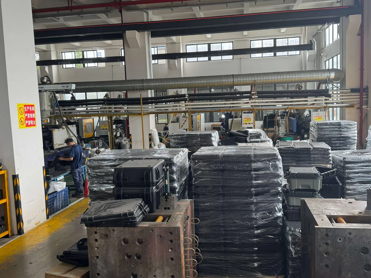
Supplier evaluation points. Because end effectors are high-value precision items, evaluate four capabilities: whether the supplier can build relief cavities accurately from 3D data rather than cutting a square hole; whether material property tables and UL94 and RoHS reports are available; whether there are real cases of precision component packaging; and whether the supplier can support precision re-measurement and arrival verification. Related frameworks are in how to choose a protective case OEM factory and the instrument case selection guide.
14. Frequently Asked Questions
Q: A tool changer fails repeatability after transport. What usually causes that? A: There are three common causes. First, side impact from movement inside the case: if the changer is not restrained with zero clearance, transport vibration makes it repeatedly strike the case wall or other metal items, and the impact travels through locating pins and the locking face, deforming pin holes or damaging the locking face. Second, the master-side and tool-side plates taking load separately: repeatability is the coupled result of both plates, so if they receive different impacts in transit, accuracy after coupling can fall outside tolerance even when each looks intact. Plates shipped as a pair should be secured in the same liner module so their relative position stays stable. Third, the locking face and pin holes not being relieved: if foam presses directly on the locking face, force acts directly on the precision datum. The recommended design is perimeter load bearing with datum relief, letting the outer cylindrical surface and outer rim carry load while the locking face and pin holes are relieved by at least 5 mm, with protective covers on the pneumatic and electrical modules and matching relief in the liner.
Q: A six-axis force sensor zero drifted after transport. Can it be recovered? A: In most cases it cannot be recovered on site and the unit must return to the factory. Force sensor zero drift generally has three causes: exceeding rated load, particularly in shear and torsion, which micro-plastically deforms the elastic body; short high-frequency shock that micro-damages the strain gauge bond layer; and severe thermal cycling beyond the compensation capability. All three are irreversible, and on-site recalibration cannot fix them because calibration corrects linearity and sensitivity but cannot repair structural deformation. The most effective protection is a combination of soft support and a hard limit: soft liner material supports the sensor in normal transport without transferring load, while a rigid limiting ring with a very small clearance sits around the sensor so that in a large impact the ring contacts first and limits displacement and deformation. Also relieve the load-bearing face completely, keep the sensor in an independent compartment, keep it at least 30 mm from the case wall, and include an arrival verification card stating the zero reading and tolerance so a no-load reading can be checked immediately on arrival.
Q: Why are pneumatic gripper rails easily damaged in transit, and how can that be prevented? A: Parallel pneumatic gripper rails, commonly crossed roller or linear guides, work under preload. Side impact in transit creates brinelling on raceways and rollers, which shows up as a gritty feel and degraded repeatability. Rails are vulnerable because the jaws act as lever amplifiers, so any force on a jaw is amplified before it reaches the rail. There are four preventive measures. Carry the gripper on its body base or side mounting face, never on jaws or rail areas. Remove jaws and pack them separately, or leave them in a naturally open position with independent relief. Never stack grippers directly, using EVA dividers at least 20 mm thick if stacking is unavoidable. And confirm before shipment that jaws are in the closed or manufacturer-specified shipping position so the rack is not left unsupported under load. Two supporting details also help. Fit dust caps to the air ports and provide a matching relief cavity, because push-to-connect fittings fracture easily under side load and a broken fitting can let the gripper arrive with a bent internal mechanism. And apply vapor-phase corrosion inhibitor film plus desiccant if the shipment crosses a humid season, since preloaded rails will otherwise show surface rust that is difficult to remove without disturbing preload.
Q: What sealing class does an end-effector case need, and what matters for ocean freight? A: IP65 is the sensible minimum, and IP67 is recommended where multimodal transport, rainy-season handling or quay storage is involved, with classes defined by IEC 60529 and GB/T 4208. Ocean freight is the harshest scenario: the interior of a container stays at 70 to 90 percent relative humidity for extended periods with severe day-night temperature cycling, and condensation forms a water film on metal surfaces and reduces insulation resistance in electronics. End effectors contain three moisture-sensitive categories: electronics in force sensors and electric grippers, internal metal mating surfaces and springs in pneumatic grippers and tool changers, and rubber cups and seals. Corrosion and moisture therefore need separate treatment. Mechanical compartments use vapor-phase corrosion inhibitor film plus desiccant, while electronics compartments use an ESD shielding bag plus desiccant and a humidity indicator card, and electronics compartments must never use oil-based rust preventive because it contaminates electronics and rubber. An IP67 case must include a pressure-equalization valve, otherwise day-night temperature differences and air or high-altitude transport will seize the lid or cause a seal rebound. Selection guidance is in the case pressure equalization valve article.
Q: How should removed gripper jaws and tooling be handled? A: Remove them and pack them separately. This is the most commonly overlooked yet most effective measure in end-effector packaging. There are two reasons: jaws and cutting tools act as lever amplifiers, so any impact on them is magnified before reaching rails or sensors; and edges, nozzles and contact tips are the most impact-sensitive features and cannot be repaired once damaged. In practice, remove jaws, cutting tools, dispensing needles and welding contact tips, and pack them in a dedicated tool compartment with protective sleeves and relief at the edges. Isolate the tool compartment from precision items such as tool changer plates and force sensors. Place heavy items such as welding torches, grinding heads and tool racks on the case floor close to the vertical walls with load-bearing structure underneath. If the customer requires shipment fully assembled, at minimum confirm jaws are in a naturally open position with independent relief and no hard contact with case or liner.
Q: Does an end-effector case need transport testing? Is visual inspection enough? A: No, and end effectors additionally require precision re-measurement. An intact appearance and successful power-up do not prove that transport was acceptable. Tool changer repeatability, force sensor zero, gripper positions and gripping force, and electric gripper encoder zero are the real criteria, and their degradation is completely invisible externally. A recommended test set includes temperature and humidity conditioning from minus 20 to plus 60 degrees Celsius at 85 percent RH, drop and random vibration per ISTA 2A or GB/T 4857, compression at the actual stacking layers, and optionally an ASTM D4169 distribution cycle. For criteria, add precision re-measurement beyond appearance and function, and include an arrival verification card listing the check method and tolerance for each item for sign-off by the receiving party. If the customer cites MIL-STD-810H, state that only the test methods are referenced, such as Methods 501, 502, 507, 514 and 516, and that this is not a military certification. Related workflows are covered in the ISTA transport testing procedure and MIL-STD-810H case compliance articles.
Q: Can several end effectors ship in one case, and how do collisions get prevented? A: Yes, but strict zoning and layering is mandatory. The recommended strategy is: heavy items such as welding torches, grinding heads and tool racks on the lower level, carried by high-density EVA at 80 to 120 kg/m3 close to the vertical walls; precision items such as tool changer pairs and force sensors on the middle level, each in its own compartment separated by EVA dividers at least 20 mm thick with relief accuracy of about plus or minus 0.5 mm; light items such as grippers, vacuum cups, cables and accessories on the upper level so they cannot press on precision items below; and a dedicated accessory cell for bolts, pins, manuals and calibration cards so small metal items cannot move freely and act as loose hammers. In addition, tool changer plates shipped as a set must be secured together in the same liner module to preserve relative position, parts of different weights must not share one compartment, and every movable metal item inside must be fully restrained. Where models change frequently, a removable divider system allows compartment dimensions to be adjusted without changing case or liner.
Q: Where does the cost of end-effector packaging go, and how can it be reduced? A: Cost concentrates in three areas: liner custom design and molding, either CNC or tooled, the case itself, either a molded custom shell or a purchased standard case, and test and inspection effort. Three approaches reduce cost. First, use a common case with model-specific liners: the end-of-arm tooling industry is characterized by many models, small batches and fast product turnover, so consolidating cases into two or three common formats and tooling only the liner dramatically lowers tooling investment. Second, validate a CNC liner prototype before committing to tooling: CNC unit cost is higher than a molded part, but a single mold modification usually costs far more than the prototype, so validating first is nearly always more economical. Third, use removable dividers to improve reuse and reduce the need for dedicated cases per model. High-value items should also prioritize sealing and relief accuracy over appearance and decorative design. JUNZHJIA can provide consolidation recommendations and cost comparisons based on the customer's end-effector list to help balance tooling investment against the number of case variants.
Q: How can a buyer tell whether a supplier's liner genuinely fits a precision part? A: Four checks work well. First, was it modeled from 3D data: a competent liner designs relief cavities and load-bearing faces from the part's 3D model or a 3D scan, rather than cutting a square hole around the outline. Second, is the relief position accurate: confirm the relative position of cavity and datum face with a fixture or vision measurement at a tolerance within plus or minus 0.5 mm, especially at tool changer locking faces and pin holes and at force sensor load faces. Third, is the support surface selection correct: non-datum surfaces such as the outer cylinder, outer rim or body mounting face should carry load while datum faces are fully relieved, and if the supplier is putting force on a locking face or load face, the design understanding is wrong. Fourth, is the extraction force reasonable: after packing, pushing the part by hand should produce less than 1 mm of movement and extraction force should be 20 to 60 N, since too loose loses restraint and too tight damages parts. Ask the supplier to produce a CNC first article for physical assembly validation before committing to tooling. Related frameworks are in the how to choose a protective case OEM factory article.
15. Conclusion and Related Reading
The value of a robot end-effector case lies in treating precision parts as precision instruments: relief cavities protect precision datum faces, zero-clearance restraint prevents movement inside the case, layering and zoning isolate heavy items from precision items, and desiccant and vapor-phase inhibitor film address the different corrosion risks of mechanical and electronics compartments. If any one of those four is missing, a tool changer pair or force sensor that looks perfect can still fail precision acceptance at the customer site, and the cost of a factory return or replacement far exceeds the case.
For procurement and engineering teams, a practical four-step plan is: first, identify the precision datum faces and relief requirements of each end effector and define relief positions and load-bearing surfaces; second, set the sealing class from the logistics route and define separate corrosion and moisture strategies for mechanical and electronics compartments; third, design the layered and zoned liner and validate a CNC first article by physical assembly to confirm relief, restraint and extraction force; and fourth, include the arrival verification card, packing SOP and material compliance declarations in the delivery documents. JUNZHJIA, operated by Kexin New Materials (Guangdong) Co., Ltd., supports end-of-arm tooling manufacturers, robot integrators and overseas channels with custom liners, OEM/ODM case structure development, model-specific gaskets and pressure-equalization valves, plus material property tables, UL94 reports, RoHS and REACH declarations and test coordination, covering everything from single-piece first articles to volume delivery.
Related Reading