


SMT feeders and nozzles are the most precise, the most expensive, and the most casually handled assets on a placement line. The conclusion first: a feeder and nozzle case cannot be designed like a toolbox. It must be designed like a case for calibrated measuring instruments. Feeders need posture locking and pick-position protection. Nozzles need individual cavities, zero tip contact, static dissipation and humidity control. The enclosure should meet IP65 or IP67 as defined by IEC 60529 / GB/T 4208, the insert should be a molded static-dissipative EVA or PE cavity system, and the whole package should be validated against the ISTA and GB/T 4857 transport test families.
The value density of these parts is extreme. A multi-module placement machine typically carries 60 to 200 feeders. A single electric feeder can cost thousands of RMB, so a complete feeder library represents a substantial asset base in its own right. Nozzles are even more concentrated in value: a micro nozzle for 0201 or 01005 components can cost hundreds of RMB, and once its ceramic or carbide tip chips, the line immediately suffers higher reject rates, placement offset and reduced throughput.
In practice, however, feeders and nozzles circulate in original corrugated boxes, foam bags, or plain plastic crates. Across cross-plant changeovers, outbound servicing, trade-show demonstrations, customer trials and equipment relocation, they are unpacked and repacked repeatedly, and damage is almost inevitable. Worse, the damage often only shows up on the line, where root-cause tracing is difficult.
This article is written for SMT equipment engineers, process engineers and asset-management buyers. It covers failure mechanisms, material selection, structural design, standards references and acceptance methodology.
Contents
- 1. Why Feeders and Nozzles Are the Most Fragile Assets in an SMT Workshop
- 2. Failure Map: How Feeders and Nozzles Break in Transit
- 3. Feeder Protection: Posture Locking and Pick-Position Protection
- 4. Nozzle Protection: Ceramic Tips, Springs and O-Rings
- 5. ESD and Cleanliness: Electronics-Bearing Feeders, Particle-Sensitive Nozzles
- 6. Humidity, Oxidation and Residual Service Oil
- 7. Insert Design: Compartments, Retention and the Zero-Contact Principle
- 8. Case Structure and Stacking: Transfer Cases Versus Long-Haul Cases
- 9. Sealing and Pressure Equalization: What IP65 and IP67 Really Mean
- 10. Materials and Flammability: UL94 and Static-Dissipative Compatibility
- 11. Standards Reference: ISTA, GB/T 4857, MIL-STD-810H and IEC 60529
- 12. Transport Validation and Acceptance: A Credible Drop and Vibration Test
- 13. Labeling, Counting and Poka-Yoke: Ending the Missing-Nozzle Problem
- 14. Maintenance, Service Life and Total Cost of Ownership
- 15. Common Misconceptions and Engineering Recommendations
- Frequently Asked Questions
- Conclusion and Related Reading
1. Why Feeders and Nozzles Are the Most Fragile Assets in an SMT Workshop
To define protection requirements, you must first understand what these two item families are physically.
What a feeder contains. A modern electric feeder includes a tape guide mechanism, a ratchet or servo tape-indexing mechanism, a cover plate and peeling blade, a step-control circuit board, a barcode or RFID tag, and a memory chip that stores feed parameters. The mechanical portion consists of precisely matched gears, springs and rails. The electrical portion consists of a low-power but static-sensitive controller. A feeder is a miniature automation machine, not a fixture. This is the fundamental difference from ordinary tooling: tooling only has to avoid being dented, while a feeder must also preserve its calibration data and its mating precision.
What a nozzle contains. A nozzle consists of a shaft, a tip and an internal vacuum channel. Miniature nozzles often use ceramic, carbide, ruby or specially coated alloy tips, with aperture diameters that can be tens of microns. The mid-section carries a precision ground mating surface and an O-ring. Some models include an internal spring buffer or a vacuum-sensing channel. Nozzle failures concentrate almost entirely on two things: tip geometry and vacuum sealing.
Why they tolerate handling worse than the machine itself. The placement machine is a passively protected object. It ships in a dedicated wooden crate with transport locking bolts and installation documentation, and handling is performed by the manufacturer or its agent. Feeders and nozzles are different. They are pulled out, mounted, transferred and shipped out constantly, and there is no unified packaging standard for them. Procurement teams often treat them as consumables, while process teams know they are precision references. That perception gap is precisely why damage rates are high.
| Item | Critical precision area | Main sensitivities | Typical consequence of damage |
|---|---|---|---|
| --- | --- | --- | --- |
| Electric feeder | Step control, gear mesh, pick height | Impact, posture deformation, dust, static | Step deviation, higher reject rate, error stops |
| Pneumatic feeder | Cylinder, throttle valve, cover plate | Impact, oil contamination, debris in air path | Unstable feeding, cover not fully seated |
| Micro nozzle | Ceramic or carbide tip aperture and flatness | Tip impact, particles, static attraction | Vacuum leak, placement offset, component flip |
| General nozzle | Shaft concentricity, O-ring | Bending, O-ring aging, corrosion | Nozzle runout, dropped parts, shaft sticking |
| Feeder calibration data | Memory chip and tag | ESD, strong magnetic fields, moisture | Parameter loss, recalibration required |
2. Failure Map: How Feeders and Nozzles Break in Transit
Grouping damage into five categories makes it possible to assign a design response to each.
Category one: mechanical damage to tips and mating surfaces. This is the most frequent failure. When nozzles are bulk-stacked, tips collide with each other or with the case wall. Ceramic edges chip and flatness degrades. A chip is not always visible to the naked eye, but the vacuum leak shows up immediately as dropped components. The line-stop cost caused by a single chipped 0201 nozzle usually far exceeds the price of the nozzle itself.
Category two: bending and loss of concentricity. Nozzle shafts are slender, and a lateral load can produce a slight bend. Once bent, the nozzle develops runout during rotational placement, placement accuracy drops, and the problem is frequently misdiagnosed as a machine accuracy issue.
Category three: feeder posture deformation and pick-position drift. The internal pick height of a feeder is determined jointly by its rails and cover plate. Without positioning and support inside a case, stacking pressure causes slow deformation, and sustained vibration during long-haul transport can loosen fasteners. The symptom is a feeder that performs normally on machine A but generates rejects on machine B.
Category four: electrostatic discharge and electrical degradation. The step-control board, sensors and memory chip are ESD-sensitive. A plastic crate in a dry environment can generate several thousand volts of static charge through friction, and discharge on contact with the feeder interface can cause latent failures that do not appear immediately but shorten service life.
Category five: moisture, oxidation and corrosion. Metal parts, springs and O-rings on nozzles and feeders oxidize or age in hot and humid environments. Residual lubricant after servicing can absorb particles under humid conditions, forming a paste-like abrasive that accelerates wear.
| Failure type | Where it occurs | Main trigger | Design response |
|---|---|---|---|
| --- | --- | --- | --- |
| Tip chipping | Handling, stacking, bulk storage | Hard impact, no individual cavity | Individual cavities plus soft insert material |
| Shaft bending | Tipping, compression | No support, no posture constraint | Vertical locating slots plus top retention |
| Pick-position drift | Long-haul vibration, stacking | Sustained vibration, static creep | Compartment support plus stacking limits |
| ESD damage | Friction in dry conditions | Insulating case, no grounding path | Static-dissipative material plus grounding |
| Oxidation and corrosion | Sea freight, rainy season | High humidity, salt spray, oil residue | Sealing plus desiccant plus rust prevention |
3. Feeder Protection: Posture Locking and Pick-Position Protection
Feeder protection can be summarized as three prohibitions: no relative displacement, no posture inversion, no static-load creep.
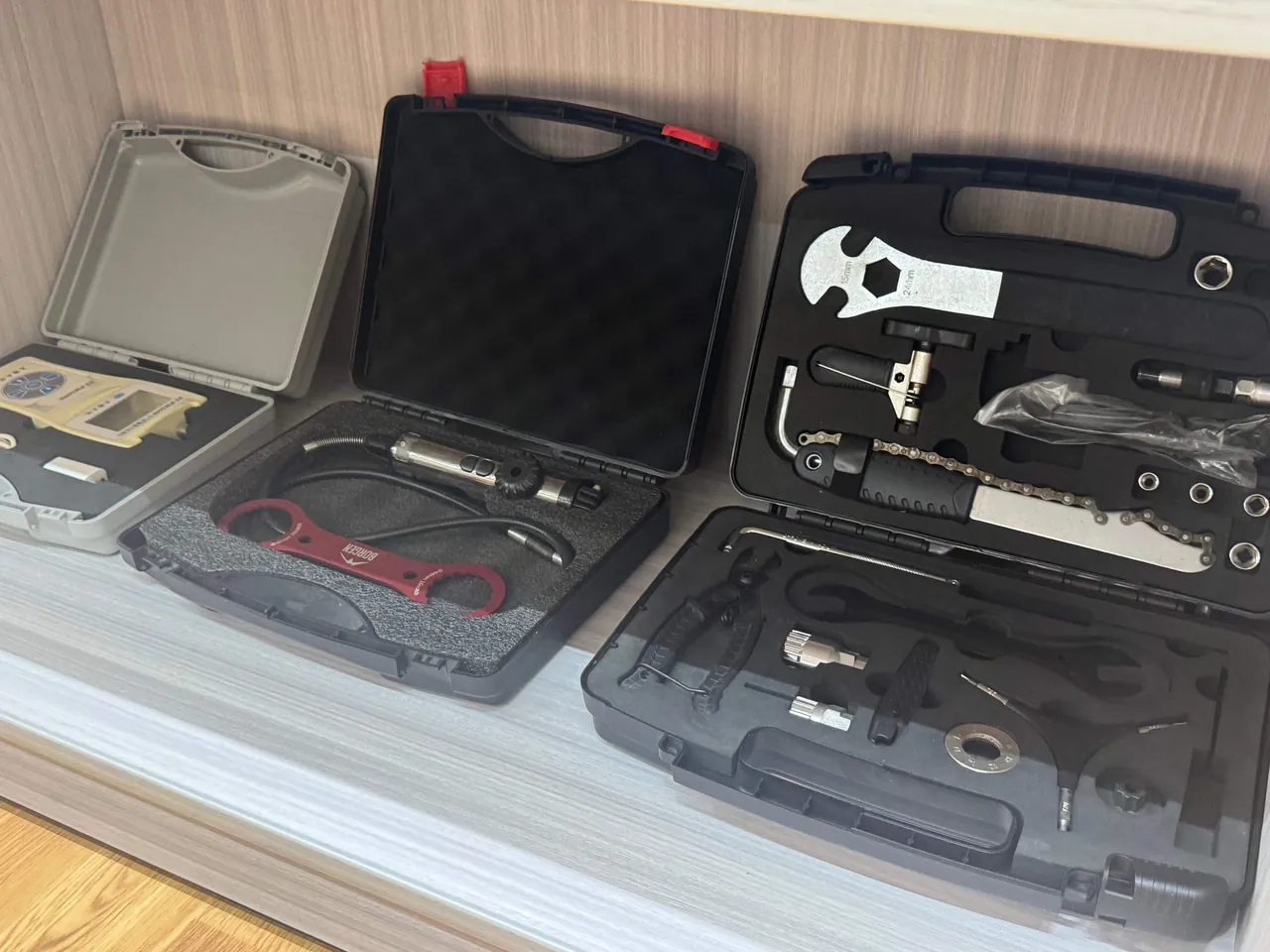
Posture locking. The ideal transport posture for a feeder matches its installed posture on the placement machine: horizontal, tape direction consistent, cover plate facing up. The reason is that internal mechanisms are then loaded in the direction they were designed for, avoiding out-of-design lateral loads. The case interior should provide a molded cavity that conforms to the feeder outline, with walls constraining all four sides and a lid insert providing light contact without compression.
Pick-position protection. The pick position sits at the front of the feeder, where the tape is lifted for the nozzle to pick from, and it is the most exposed protruding feature. No rigid component inside the case should press directly on this area. Where necessary, leave a 3 to 5 mm clearance at the front of the cavity, or wrap it in soft EVA so that any potential impact surface becomes elastic rather than rigid.
Protecting the indexing mechanism. The step is determined jointly by the ratchet or servo mechanism and the cover plate. During transport the cover plate should be closed and restrained so it cannot swing freely. Some feeders provide a dedicated transport lock position, and this should be engaged per the manufacturer's instructions before packing.
Group transport versus single-unit transport.
- Single-unit transport (outbound servicing, repair round trips): fewer cavities, more generous dimensions, with the emphasis on individual cavities and carrying convenience.
- Group transport (cross-plant changeover, equipment relocation): 30 to 200 feeders must be loaded in bulk, counted efficiently and stacked stably, usually with multi-layer drawers or slotted dividers.
- Mixed-model transport (multiple widths in one case): 8 mm, 12 mm, 16 mm and 24 mm widths differ considerably, so adjustable dividers or specification-zoned molded inserts are required.
For implementation approaches to adjustable partitioning, see removable divider system design.
4. Nozzle Protection: Ceramic Tips, Springs and O-Rings
Nozzle protection logic is entirely different from feeder protection. Feeders fear deformation. Nozzles fear contact.
The zero-contact principle for tips. The ideal nozzle cavity lets the nozzle drop vertically into a precisely sized bore, where the bore wall engages only the shaft mid-section while the tip either hangs free or touches only soft material. Any external force is then carried by the shaft and bore wall, and the tip takes no load at all. In engineering terms this is achieved with a molded insert and a stepped bore: the upper bore diameter matches the shaft, and the lower bore is enlarged to form a tip clearance pocket.
Anti-inversion and anti-release. Cavities must keep nozzles in place even if the case is inverted, tilted 90 degrees or accidentally dropped. Three common approaches exist: cavity depth greater than two thirds of nozzle length; a slight necking at the cavity mouth to provide light gripping; and a transparent or translucent cover plate pressing down on a full row of nozzles.
Managing stress in springs and O-rings. A spring-buffered nozzle stored under continuous compression will experience stress relaxation, and an O-ring under sustained lateral squeeze deforms permanently. For storage longer than three months, choose a cavity that lets the spring sit in its natural or lightly compressed state rather than fully compressed.
Differentiated handling for special nozzles.
- Micro nozzles (0201 and 01005 class): extremely brittle tips, individual cavities mandatory, no stacking of any kind.
- Multi-nozzle heads: larger overall dimensions requiring full-area support rather than point support.
- Specialty nozzles (connectors, LEDs, shields): cavities should follow the maximum outline and support the longest cantilevered section.
- Nozzles with vacuum-sensing channels: the cavity must keep channel openings unobstructed and avoid long-term contact with oily materials.
| Nozzle type | Tip material behaviour | Cavity design points | Common mistake |
|---|---|---|---|
| --- | --- | --- | --- |
| Micro chip nozzle | Ceramic or carbide, very brittle | Stepped bore with free-hanging tip | Wrapping in bubble film |
| General chip nozzle | Alloy steel, more ductile | Vertical bore with necked grip | Mixing types in one pocket |
| Specialty nozzle | Varied, includes coated faces | Profile molding with cantilever support | Sizing by longest edge only |
| Multi-nozzle head | Composite structure | Full support plate with surface contact | Leaving it unsupported |
5. ESD and Cleanliness: Electronics-Bearing Feeders, Particle-Sensitive Nozzles
The real ESD risk. Unprotected contact between a feeder control board or memory chip and a charged object can produce hard or latent failure. Nozzles themselves are mostly metal or ceramic and appear insensitive to static, but in dry environments they attract airborne particles through static charge, gradually clogging the vacuum channel. In feeder and nozzle handling, static control protects both the electronics and the cleanliness of the product.
Practical measures. Use static-dissipative EVA or PE for inserts and dividers, with surface resistance held inside the static-dissipative band (a commonly cited working range is roughly 10 to the fifth through 10 to the eleventh ohm, though the exact band and test method should be fixed in the technical agreement). If the case has a metal frame or metal hinges, provide a grounding point that can be bonded to the ESD workstation surface. Avoid ordinary bubble film for lid inserts, because it is a strong insulator and generates significant triboelectric charge.
Cleanliness control. SMT workshops are sensitive to particulate contamination, so nozzles and feeders should be cleaned before packing. Cleaning before packing matters more than sealing after packing: sealing only blocks external contamination and cannot remove particles already inside. A recommended sequence is: clean with compressed air or dedicated cleaning equipment, verify vacuum channel patency, dry, load into a clean insert, add desiccant and seal.
Material requirements for clean enclosures.
- Insert materials should not shed. Avoid low-density, cheap foams that crumble.
- Inserts should be cleaned before assembly, and machining debris from forming must be removed.
- If the insert surface starts to powder or chalk after long use, replace it rather than continuing to use it.
For static shielding design details, see ESD shield case design. For a cross-comparison of insert material systems, see case foam material comparison.
6. Humidity, Oxidation and Residual Service Oil
Three ways humidity affects feeders and nozzles.
First, metal part oxidation. Feeder rails, springs and fasteners are commonly carbon or alloy steel, and they corrode slowly in environments with sustained relative humidity above 60 percent. Corrosion is not only cosmetic; it changes mating clearances.
Second, O-ring and rubber aging. Rubber hardens and cracks in hot, humid and ozone-bearing environments, losing its sealing ability. Humidity control during transport and storage can meaningfully extend its life.
Third, lubricant emulsification. Residual service oil can absorb water in humid conditions and emulsify into a viscous contaminant, which then captures particles and becomes an abrasive medium that accelerates rail and gear wear.
Sealing and desiccant sizing. With an IP65 or IP67 sealed case, internal humidity is determined by initial humidity and desiccant capacity. Desiccant quantity should be calculated from internal free volume, target humidity, packaging material moisture vapour transmission rate and expected transit duration, not estimated by feel. A humidity indicator card is normally added so that moisture ingress can be judged at a glance when the case is opened. For sealing material and structural options, see case seal materials and structure.
The rust-prevention trade-off. For long-term storage beyond six months, vapour corrosion inhibitor materials combined with a sealed case can be used. Verify compatibility between the VCI material and the static-dissipative insert, and confirm that residue will not contaminate the tape path.
7. Insert Design: Compartments, Retention and the Zero-Contact Principle
The insert is the core of the protection system. The case defines the external environment; the insert defines the internal load path.
Three mainstream insert approaches.
Approach one: molded EVA cavity insert. Produced by CNC cutting or compression molding to give every feeder or nozzle its own cavity. Advantages are high locating accuracy, repeatable batch production and a tidy appearance. The drawback is that a drawing is needed for each model, and mixed-model scenarios require modular designs that can be recombined.
Approach two: EVA padding with adjustable dividers. A flat EVA layer at the base and around the perimeter, with adjustable dividers in the middle. The advantage is adaptability at lower cost; the drawback is that locating accuracy depends on assembly, and dividers can loosen over time.
Approach three: molded tray plus individual small boxes. Each nozzle or feeder group goes into its own small box, which then goes into the case. This is the most flexible and simplifies distribution to multiple plants, but it is the least volume-efficient.
Critical surface details.
- EVA surfaces should be treated against shedding, so that prolonged friction does not generate debris that contaminates nozzle tips.
- Cavity floors should carry a 1 to 2 mm soft buffer layer to absorb vertical impact.
- Cavity walls should include a small clearance in their fit tolerance. Too tight makes loading and removal difficult and causes friction damage; too loose loses locating function.
- The insert-to-case interface should be removable for cleaning and replacement.
For the design workflow and process points of custom inserts, see custom foam insert design guide and EVA foam insert custom process.
8. Case Structure and Stacking: Transfer Cases Versus Long-Haul Cases
The same feeder batch can move through three scenarios, and the case requirements differ.
Scenario one: in-workshop transfer. Short distance, high frequency, fixed operators. The emphasis is on handling efficiency, visibility and light weight. High sealing grades are usually unnecessary here, but ESD requirements must not be relaxed.
Scenario two: cross-plant changeover and equipment relocation. Medium distance, road transport, many handling cycles. The emphasis is stacking stability, drop resistance and poka-yoke labeling.
Scenario three: international sea and air freight. Long distance, complex environment, exposure to salt spray and temperature-humidity cycling. The emphasis is sealing grade, pressure equalization and rust prevention. For long-distance strategy, see transport packaging test procedures and ISTA.
Stacking design boundary conditions.
| Parameter | Workshop transfer case | Cross-plant case | Export case |
|---|---|---|---|
| --- | --- | --- | --- |
| Typical stack layers | 3 to 5 | 2 to 3 | 1 to 2 |
| Sealing requirement | Basic | IP65 common | IP67 common |
| Pressure equalization | Usually not needed | Recommended | Recommended |
| Locking method | Latches | Reinforced latches plus lock holes | Reinforced latches plus lock and seal |
| Wheels | Common | Optional | Normally omitted |
| Labeling | Bin label | Model, quantity, QR code | Model, quantity, batch, barcode |
Why pressure equalization is necessary. A sealed case undergoes altitude and temperature changes during transport, creating a pressure differential. When that differential exceeds the sealing capability, seals can be pushed open, the case can bulge and deform, or the case can become impossible to open. A pressure equalization valve releases the differential in a controlled way while preserving the IP rating. For the underlying principle, see case pressure equalization valve and waterproof case IP ratings explained.
9. Sealing and Pressure Equalization: What IP65 and IP67 Really Mean
IEC 60529, and its equivalent GB/T 4208, expresses enclosure protection with two digits. The first digit covers solid particle ingress including dust, and the second covers water.
| IP rating | Dust meaning | Water meaning | Typical SMT positioning |
|---|---|---|---|
| --- | --- | --- | --- |
| IP54 | Limited dust protection | Splash resistant | In-workshop transfer |
| IP65 | Dust tight | Jet-water resistant | Cross-plant road transport |
| IP67 | Dust tight | Short-term immersion | Sea freight, rainy season, intermodal |
| IP68 | Dust tight | Continuous immersion | Special cases only, not chosen by default |
Misconceptions worth clearing up.
Misconception one: IP67 means absolutely no water ingress. It actually means no ingress under defined test conditions for a defined duration. Aged seals, more open-close cycles and debris on sealing faces all reduce real-world capability.
Misconception two: higher is always better. Higher ratings generally mean tighter sealing and greater opening resistance, and they make the internal pressure issue more pronounced. For a feeder case used frequently inside a workshop, IP54 to IP65 is often the more rational choice.
Misconception three: judging the case by its rating and ignoring the seals. Protection is limited by the weakest link. The case body may be one-piece molded, but the gasket, hinges, latches and pressure valve are all potential leak paths. The gasket material, its compression set behaviour and its replacement interval directly determine the real service life of the case.
10. Materials and Flammability: UL94 and Static-Dissipative Compatibility
Case body materials. The mainstream choice is a copolymer polypropylene injection-molded case, offering chemical resistance, good toughness and recyclability; high-density polyethylene is used in some applications. Material should be rated for flammability per UL94. UL94 V-0 means that in the vertical burning test the specimen self-extinguishes within 10 seconds after flame removal and does not produce dripping that ignites cotton, which is a common requirement in electronics manufacturing and warehousing.
The compatibility problem between antistatic and flame-retardant performance. Antistatic function is normally achieved with carbon black, conductive fillers or antistatic masterbatch, while flame retardancy is achieved with flame retardants. Adding both can cause mutual interference: conductive fillers can affect the char-forming behaviour of the flame retardant system, and flame retardants can affect the formation of the conductive network. When both properties are required, rely on measured data from the finished part rather than quoting raw material data separately.
Practical durability considerations. Antistatic performance decays over time at a rate influenced by ambient humidity, cleaning method and UV exposure. It is advisable to specify both an initial resistance band and a periodic retest requirement in the technical agreement.
11. Standards Reference: ISTA, GB/T 4857, MIL-STD-810H and IEC 60529
Standards are the shared language of protective design. The table below summarizes the most relevant standards and their scope boundaries.
| Standard | Subject area | Use in this context | Notes |
|---|---|---|---|
| --- | --- | --- | --- |
| IEC 60529 | Enclosure protection (IP code) | Definition and verification of sealing grade | Equivalent to GB/T 4208 |
| GB/T 4208 | Enclosure protection (IP code) | Domestic acceptance basis | Technically aligned with IEC 60529 |
| ISTA series | Transport package performance testing | Drop, vibration, stacking, concentrated impact | Select procedure by channel and mode |
| GB/T 4857 series | Basic tests for transport packages | Drop, vibration, stacking, compression | Common for domestic road transport |
| ASTM D4169 | Shipping container performance testing | Distribution cycle simulation | Common for North American export |
| MIL-STD-810H | Environmental test methods | Temperature, humidity, vibration, shock methodology reference | Methodology reference only, not a military certification |
| UL94 | Flammability of plastic materials | Case and insert flammability rating | Specify specimen thickness and orientation |
| ANSI/ESD S20.20 | ESD control program | ESD management for handling and packaging | Complements IEC 61340-5-1 |
| ANSI/ESD S541 | Packaging for ESD-sensitive items | Packaging material selection and acceptance | Primary basis for insert selection |
Correct framing for MIL-STD-810H. This is a United States Department of Defense environmental test methods standard covering temperature, humidity, vibration, shock and salt spray, among others. When cited in a commercial protective case context, the meaning is that the corresponding methods were used to run environmental tests, not that a military certification was obtained. Marketing and contract documents should state this distinction explicitly to avoid compliance risk. See MIL-STD-810H environmental testing and case compliance.
12. Transport Validation and Acceptance: A Credible Drop and Vibration Test
The core logic of validation: define the worst case first, then prove the case survives it.
Step one: define the distribution environment. Establish the transport modes (road, sea, air, parcel), number of handling cycles, stacking layers, temperature and humidity range, and whether forklift handling occurs. This step determines the severity level of subsequent testing.
Step two: select the test procedure. Domestic road-dominant transport commonly references the GB/T 4857 series; North American export can reference an ASTM D4169 distribution cycle; e-commerce and parcel channels commonly use ISTA 3A or 2A procedures. When selecting a procedure, note whether the test unit is a single case or a full pallet, because the severity differs significantly.
Step three: define acceptance criteria. Criteria must be quantified, for example: no case rupture, no seal failure, no displacement of insert cavities, and feeders that can go straight onto the line afterwards with no abnormal rise in reject rate. A pass without quantified criteria is meaningless.
Step four: execute and record. Record drop height and orientation, vibration duration and spectrum, stacking load and duration, internal humidity before and after, and the opening inspection results.
On sampling. Consistency control for custom cases can follow AQL sampling practice; see custom case acceptance and AQL sampling. For long-distance intermodal scenarios, see GB/T 4857 transport packaging testing and ASTM D4169 distribution cycle testing.

13. Labeling, Counting and Poka-Yoke: Ending the Missing-Nozzle Problem
The hidden source of loss is invisibility. The most common loss of feeders and nozzles during repeated circulation is not damage but loss and mismatch.
A three-level labeling system.
- Case level: an external label showing the owning workshop or customer, feeder model range, quantity, responsible person and last calibration date.
- Cavity level: a model number printed or applied next to each cavity that corresponds one-to-one with its intended content, so verification is immediate on opening.
- Item level: individual nozzle boxes or feeder bodies retain their original serial labels, with a QR-coded manifest inside the case where necessary.
Engineering the counting process. For cases holding more than 60 feeders, checking item by item is slow and error-prone. Workable approaches include numbering cavities in the same order as the manifest so counting follows sequence, or using a QR-coded manifest with a handheld terminal for batch scanning.
Poka-yoke design. Cavities sized differently for different feeder models physically prevent misloading, and similarly sized nozzles can be distinguished by differently coloured cavity liners. Physical error prevention beats procedural error prevention, because procedures get rushed during production pressure and physical structures do not.
14. Maintenance, Service Life and Total Cost of Ownership
Maintenance points for case and insert.
- Inspect gaskets periodically: look for hardening, cracking and deformation, and check sealing faces for dust and tape debris. Restore elasticity after cleaning.
- Inspect latches and hinges periodically: latch spring fatigue reduces clamping force, and hinges are stress concentration points where cracks should be checked.
- Clean inserts: use a neutral cleaner and a soft cloth. Avoid solvent cleaners, which can damage the antistatic layer.
- Insert replacement criteria: obvious cavity deformation, surface powdering, or antistatic retest outside specification.
For cleaning procedure details, see how to clean a protective case; for factors affecting case life, see protective case service life and influencing factors.
Components of total cost of ownership.
| Cost item | One-off purchase approach | Long-term system approach |
|---|---|---|
| --- | --- | --- |
| Case and insert purchase | Low | Higher |
| Feeder and nozzle replacement | High | Low |
| Line-stop losses | High and unpredictable | Low |
| Counting and traceability labour | High | Low |
| Calibration and re-verification | Frequent | Scheduled |
| Overall outcome | Cheap initially, expensive over time | Higher initially, better over time |
The decisive term is line-stop cost. A chipped micro nozzle is a modest loss in itself, but the resulting rejects, placement defects, line-stop troubleshooting and customer complaints can cost hundreds of times the nozzle price. Protection investment should be evaluated as avoiding one line stop, not as replacing a corrugated box.
15. Common Misconceptions and Engineering Recommendations
Misconception one: using an ordinary plastic crate. It is insulating, provides no locating, no sealing and unstable stacking, and it actively generates static charge. This is the most common wrong choice.
Misconception two: wrapping everything in bubble film. Bubble film is point-contact rigid support for a nozzle tip and is a strong insulator that generates pronounced triboelectric charge.
Misconception three: a case without an insert. The case handles the external environment, the insert handles the internal load path. A case without an insert is simply a sealed empty cavity in which precision parts collide freely.
Misconception four: mixing feeders and nozzles in the same compartment. Feeders are much heavier, and their inertia during transport strikes nozzles directly.
Misconception five: ignoring pressure relief. A sealed case can become difficult to open or damage its seals due to pressure differentials in air freight and temperature swings.
Engineering recommendation checklist:
- Build a feeder and nozzle inventory that records quantity and critical dimensions for each model.
- Prefer molded EVA cavity inserts, and design reconfigurable modules for mixed-model scenarios.
- Select the sealing grade from the distribution environment rather than chasing the highest rating.
- Use static-dissipative insert material and provide a grounding path in the case.
- Fit desiccant and a humidity indicator card, with a documented sizing basis.
- For long-term storage, avoid keeping nozzle springs fully compressed.
- Establish a cavity-level labeling system so verification happens on opening.
- Write the transport test procedure and quantified acceptance criteria into the technical agreement.
- Agree spare part and replacement intervals for the case and insert with the supplier.
On supplier selection. In OEM and ODM cooperation, confirm whether the supplier can support insert drawing review, sample trial fitting, sealing grade testing and transport test coordination. In the protective case sector, JUNZHJIA provides end-to-end support from case selection and insert customization through sealing and transport validation, and its manufacturing system under Kexin New Materials (Guangdong) Co., Ltd. supports developing molded inserts by feeder and nozzle model, configuring static-dissipative materials on request, and issuing relevant inspection and trial-fitting records as required. For selection methodology, see instrument case selection guide and how to choose a case OEM factory.
Frequently Asked Questions
Q: Does an SMT feeder case always need an IP67 rating? A: No. The right grade depends on the actual distribution environment. IP67 means dust tight and protected against short-term immersion, which suits sea freight, rainy-season intermodal transport and outdoor transfers where standing water may be encountered. If feeders only move between workshops on the same site and all handling happens indoors, IP54 to IP65 is usually sufficient. Over-sealing brings side effects: greater opening resistance, a more pronounced internal pressure differential and higher cost. What deserves more attention is whether the insert provides individual cavities, whether posture is locked, whether materials are static dissipative and whether stacking is stable. The correct method is to map the complete flow path of the feeders, identify environmental risk at each step, and work back to a sealing grade rather than defaulting to the highest. If one case must serve both scenarios, specify for the highest-risk scenario and fit a pressure equalization valve.
Q: Can nozzles be wrapped individually in foam or bubble film for transport? A: It is not recommended. Bubble film and ordinary foam bags cause two problems. First, they create point-contact rigid support against the nozzle tip, so once a bubble bursts the load transfers directly to the tip. Second, these materials are usually strong insulators that generate noticeable static charge through friction, attracting particles that contaminate the vacuum channel. The correct approach is a molded insert with a stepped bore, so the bore wall engages the shaft mid-section while the tip hangs free or touches only soft material. If secondary individual wrapping is genuinely required, use a sleeve made from static-dissipative material, and still place it inside a case with individual cavities. The basic principle is that external forces should be carried by structure, not by precision features.
Q: What is wrong with mixing feeders and nozzles in one case? A: The core problem is the difference in mass and inertia. A feeder is typically much heavier than a nozzle, so acceleration and deceleration during transport produce a large inertial force, and if the two share a compartment the feeder strikes the nozzles directly. In addition, sharp features such as the tape guide mechanism and cover plate can scratch nozzles. The sensible solution is zoning: separate areas within one case for feeders and nozzles with a solid insert wall between them, or two separate cases managed through a unified label and manifest system. If quantities are too small to justify two cases, at minimum separate them with a solid insert wall and keep the nozzle zone in the centre of the case rather than at the edge.
Q: Do antistatic materials lose effectiveness over time, and how often should they be retested? A: Yes. Antistatic performance is delivered mainly through conductive fillers or antistatic masterbatch, and its effect decays with humidity variation, cleaning method, UV exposure and mechanical wear. The rate depends heavily on usage intensity, so no single fixed interval applies universally. In practice, specify the initial surface resistance band and the test method in the technical agreement, retest a sample at a fixed interval during use (quarterly or semi-annually, for example), and schedule replacement when results fall outside the agreed band or when the insert surface visibly powders, whitens or loses gloss. The key is to write the retest requirement into the technical agreement and maintenance procedure, rather than tracing back after an ESD incident occurs.
Q: A sealed case cannot be opened after transport. What causes this? A: This is normally caused by a pressure differential. During transport a sealed case experiences altitude and temperature changes. As temperature falls, the internal air volume contracts and creates negative pressure, so external atmospheric pressure clamps the lid shut and makes opening difficult. Conversely, high temperatures can create positive internal pressure that pushes the gasket open and causes sealing failure. The solution is a pressure equalization valve, which allows gas to pass at a controlled rate while maintaining the IP rating through a hydrophobic membrane structure. When selecting one, consider its air flow rate, waterproof rating and temperature range. If the case is already bulging or the gasket has turned outward, check whether a valve was omitted or was undersized.
Q: Is EVA or PE foam the better insert material? A: They serve different roles. EVA can be CNC cut or molded into high-accuracy cavities and its surface can be treated against shedding, making it suited to feeder and nozzle applications that need individual cavities and precise locating. PE foam, including the pearl-cotton type, costs less and cushions well, but its forming accuracy and long-term dimensional stability are generally inferior, making it better for padding and filling. A common engineering combination uses molded EVA cavities for structural locating and PE foam padding at the base and around the perimeter. Selection should weigh cushioning, forming accuracy, antistatic capability, chemical resistance and long-term dimensional stability together, then be confirmed by trial fitting with actual models.
Q: Does the feeder insert need a dedicated design for every model? A: It depends on the number of models and how often they are mixed. If a customer uses only a few feeder models, for example two widths, a dedicated molded insert gives the best locating. If models are numerous and combinations change frequently, a modular approach is better: develop a standard module per specification and assemble them as needed inside the case, or use adjustable dividers with a flat EVA base layer. Modular designs take a little more development effort up front but adapt better later and simplify spare part management. Either way, complete the model inventory before development, covering outline dimensions, most sensitive features, weight and stacking requirements, and confirm with a physical trial fitting.
Q: What additional considerations apply to feeder cases for sea freight export? A: Sea freight involves long duration, large temperature and humidity cycling, and possible salt spray. Four points matter. First, use a sealing grade of at least IP67 with a pressure equalization valve. Second, fit adequate desiccant and a humidity indicator card, with desiccant sized from internal free volume and expected transit duration. Third, apply rust prevention to metal parts, and consider vapour corrosion inhibitor material for long-term storage after confirming compatibility with the static-dissipative insert. Fourth, include batch and barcode information on labels to support customs clearance and arrival verification. It is also advisable to run a full transport test before shipment, validating against the ISTA or GB/T 4857 procedure for the chosen channel and writing quantified acceptance criteria into the contract.
Q: How should the return on investment for a feeder and nozzle case be assessed? A: Assess it as avoided line-stop loss. The calculation includes annual replacement quantity and cost for feeders and nozzles, average line-stop hours caused by feeding or nozzle problems multiplied by the hourly loss, labour spent on counting and traceability, and the quantity lost or damaged during outbound servicing. Compare the sum against the purchase cost of cases and inserts. In most operations, avoiding one medium-scale line stop recovers the investment. Beyond direct cost, consider reliability benefits: stable feeding reduces reject-rate fluctuation, fewer precision problems reduce customer complaints, and cross-plant changeovers become faster. These indirect gains often exceed the direct savings in spare parts.
Conclusion and Related Reading
Protecting SMT feeders and nozzles is fundamentally an asset management engineering exercise. The goal is not simply to pack them, but to ensure that these precision items still hold their factory accuracy state after every transfer: workshop circulation, cross-plant changeover, outbound servicing and export sea freight. The path can be summarized in four steps: define the distribution environment and failure risks, design insert cavities as if for calibrated instruments, select sealing and static-control grades according to actual risk, and complete acceptance through transport testing with quantified criteria.
On the supply side, a manufacturer able to support insert drawing review, sample trial fitting, sealing grade testing and transport test coordination substantially reduces project iterations. In protective case customization, JUNZHJIA supports developing molded inserts by feeder and nozzle model, configuring static-dissipative materials and sealing solutions, and cooperating with customers on trial fitting and acceptance records, making it a suitable partner for SMT equipment and electronics manufacturers that need stable long-term supply and OEM/ODM cooperation.
Related Reading