

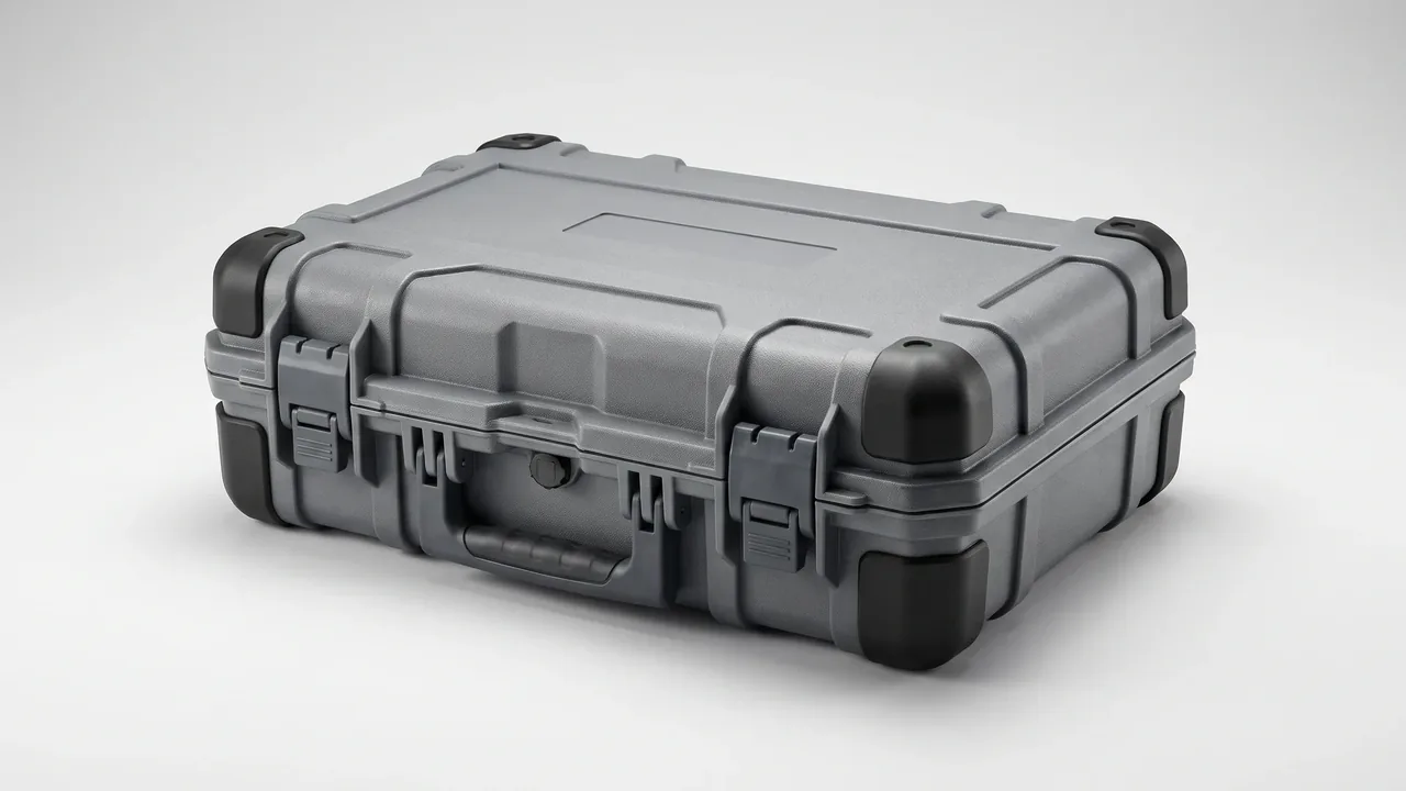
The filling valve and the capping head are the two most vulnerable assemblies on a wine bottling line. One has to complete a fixed-volume fill in roughly three tenths of a second; the other has to drive a 29 mm crown cap over the bottle flange under six to eight bar of compressed air. If either part arrives at the destination plant out of specification after a three-day overland haul, the line stops and waits for a replacement.
The root cause is that both assemblies are usually packed while still carrying the temperature, the wine residue, and the assembly stress of the production floor. Passing a pressure test at the factory does not mean the part is usable on arrival. Residual sugar crystallises inside a sealed valve chamber, fluororubber seals shrink in the cold, and a valve needle guidesleeve binds after vibration. None of these failures show up before dispatch.
JUNZHIJIA holds one principle: filling valves and capping heads must be protected to an "immediately usable on line" standard, not to a "will not visibly break" standard. The job of the case is not to keep parts from being damaged in transit. It is to deliver parts that still pass a metering accuracy recheck, a gas tightness test, and a crown cap bite test. What follows works through six threads: residue cleaning, valve fatigue, seal media, capping head mechanics, bottle mouth behaviour, and closed-loop acceptance.
Table of Contents
- Cleaning Residual Wine and Sugar Crystals Out of Filling Valves
- Valve Needle Fatigue and Batch Metering Consistency
- Seal Media Choices for Wine-Agressed Filling Valves
- Capping Head Air Pressure Matching and Crown Cap Bite
- Capping Blade Wear and Cutter Protection
- Protecting Bottle Flanges and Threads in Transit
- Seal Shrinkage and Recovery Under Cold Chain Conditions
- Splash and Cross-Contamination Control at Adjacent Stations
- Compartment Split Foam Against Liquid Slosh and Shock
- Metering Accuracy Verification Before and After Packing
- Overland Vibration and Stack Load for Complete Line Assemblies
- Arrival Acceptance: Leak Down, Pressure Drop, and Bite Sampling
- Frequently Asked Questions FAQ
- Conclusion and Related Reading
Cleaning Residual Wine and Sugar Crystals Out of Filling Valves
The filling valve is the most direct wine-contact component on the line. Its typical construction is a stainless steel valve body with a PTFE or carbide seat, a needle driven vertically by compressed air, a return spring, and a piston chamber that defines the fixed volume. Wine residue collects in three places: the seat sealing face, the needle shoulder, and the piston chamber.
The problem with residual wine is not dirt. It is what happens next. Fructose syrup and residual sugar dry into a hard crystalline layer inside the seat gap. That layer has an irregular geometry, so on the next startup the seat cannot guarantee a continuous sealing line. Once the seat leaks, filling accuracy drifts from plus or minus 0.5 percent to plus or minus 2 percent, and the whole batch fails specification.
Cleaning has to happen before packing, not after arrival. The recommended sequence is a first pass of 60 degrees Celsius warm water with a food-grade neutral detergent circulated twice, a rinse at 40 degrees Celsius until no foam remains, then drying until no water film is visible on the chamber wall. Never use a chlorine-bearing cleaner. 316L stainless steel pits when chloride ions attack the passive film, and seat retaining rings are usually passivated. Once pitting begins, those pits become the new harbour for residue.
After cleaning, inspect the chamber visually and wipe it with white cloth. Use a lint-free cotton cloth and wipe in one direction along the seat sealing face; do not scrub back and forth. No hard particles may transfer onto the cloth.
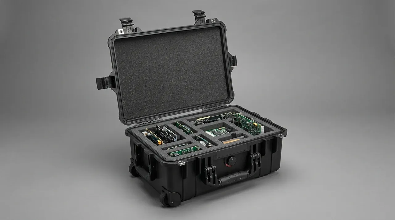
Even after a proper clean, a trace of residue remains at packing time. That is precisely the value of compartment separation. Put a barrier bag between the part and the foam: a 60 micron food-grade PE bag, heat sealed, with no desiccant inside, so that absorbed moisture is not trapped inside the valve chamber. The general approach follows the practice described for food and beverage processing line cases.
Valve Needle Fatigue and Batch Metering Consistency
Fill accuracy on a filling valve is set by the needle stroke position. The needle travels only a few millimetres, and the force path runs through three stages: air cylinder, push rod, needle. A gap change at any one stage shows up in the fill volume.
The classic fatigue failure is wear inside the guidesleeve that lets the needle develop a small lateral wobble. The wobble itself is invisible, but it turns the contact line between needle and seat from a single straight line into a broken arc. Liquid film thickness along a broken arc is uneven, so the compressibility rebound on admission differs, and fill volume swings by tens of millilitres bottle to bottle.
Batch consistency is the harder problem. Customer complaints rarely say "this one bottle is wrong." They say "all twelve thousand bottles in this batch are 0.4 percent low." That kind of systematic offset does not come from a single valve. It comes from assembly baseline variation: flange parallelism on each valve body, free length of each spring, stroke setting on each cylinder. If any of those disperse too widely, the batch shifts even though every individual valve is inside its own tolerance.
The packing plan therefore does three things.
First, one cavity per valve. Never let two valves share a foam pocket. With a shared pocket the two valves knock against each other in transit, and a valve body meeting a carbide seat is a hard-on-hard impact; one knock is enough to disturb the seat sealing line. The compartment logic is the core idea behind beverage bottling parts compartment cases.
Second, ship a configuration file with every case. It records stroke setting in millimetres, cylinder inlet pressure in bar, calibrated fill volume in millilitres, and the direction of deviation. One file per case, with packing photographs retained.
Third, buy spares as a set. Spares for the same valve model on the same line should be purchased together, calibrated together, and packed together. Mixing batches and mixing calibrations makes any batch-level deviation impossible to trace.
Seal Media Choices for Wine-Agressed Filling Valves
Wine is a weak acid at 12 to 15 percent alcohol and pH 3.2 to 3.6, and it carries tannins and tartrate esters. Those conditions attack elastomers in three ways: volumetric swelling, hardness increase, and migration of plasticiser or extractables.
Swelling raises the compression ratio inside the chamber. Once compression exceeds the design value, friction rises, and needle travel resistance rises with it. The symptom on the line is slow needle motion, a falling cycle rate, or a stall at mid-stroke when air pressure is marginal.
Hardness increase is subtler. Fluoroelastomer in an alcohol-bearing medium slowly gains crosslink density, moving from Shore A70 toward A80 or above. Nothing has broken, but the clearance is now wrong.
For wine contact, EPDM is the first choice. EPDM swells less than 3 percent in 12 to 15 percent ethanol, works from minus 40 to 150 degrees Celsius, and meets FDA and GB 4806 food-contact requirements. Fluoroelastomer handles higher temperature and oils better, but its long-term alcohol resistance is worse than EPDM, and some grades taint the wine with an off-note. In wine that is a hard failure: at 0.1 parts per billion, the note is still detectable at a tasting table.
PTFE gaskets or PTFE-clad EPDM belong only in high-temperature duties such as CIP steam sterilisation. PTFE tolerates every alcohol-bearing medium, but it creeps under sustained compression, so PTFE gaskets need a travel limit that constrains how far they can be crushed. A detailed comparison sits in gasket and O-ring material selection.
| Location | Medium condition | Recommended seal media | Hardness | Governing constraint |
|---|---|---|---|---|
| --- | --- | --- | --- | --- |
| Seat sealing face | Wine at 12-15 percent vol | EPDM 65-70 ShA | A65-A70 | Swell at or below 3 percent; no nitrile |
| Piston chamber seal | Sugared wine | EPDM 70 ShA | A70 | Friction ceiling of 3 N |
| Needle guide seal | High-cycle reciprocation | Food-grade PTFE ribbon | - | Edge tear protection required |
| Air-side seal (no wine contact) | Compressed air | FKM 75 ShA | A75 | Air side only |
For ageing signs and replacement intervals, see seal ageing and replacement guidance.
Capping Head Air Pressure Matching and Crown Cap Bite
A capping head works on an entirely different principle from a filling valve. The valve controls volume; the capping head controls force and displacement. Forming a proper seal on a standard 29 mm crown cap requires the head to deliver enough force at the end of its stroke while limiting rebound travel, so the skirt is forced past the flange and deformed permanently.
Three parameters matter.
Air pressure matching. Most cappers run on 6 to 8 bar compressed air through a regulator group into the actuator cylinder. Pressure too low and the force is insufficient: the cap stops at the flange, and the whole row dep palletises when someone rocks the bottles. Pressure too high and the cap is driven past design; the flange creeps under sustained load, the seal fails, and the glass itself can pick up hairline cracks.
Compression displacement. A mechanical stop sets how far the head travels down. Too short and the cap never bottoms out. Too long and the cap is over-driven. Displacement is tied directly to bottle height, cap height, and glass wall thickness.
Torque. Screw-cap heads also carry a defined torque setting.
These three are not independent. Pressure is the input, displacement is the constraint, torque is the result. What transport protection has to preserve is the ability to recalibrate all three after arrival, which means the case must not lock a regulator at a fixed setting. A regulator locked down will drift slowly under transport vibration, and on arrival you cannot tell whether the drift came from the lock nut moving or from something else. Protect the cylinder and the hose fittings in a separate small cavity, and fit dust caps on the air ports.
Crown caps are delicate too. A crown cap is a thin stamping, and skirt deformation is irreversible once it happens. A cap that fails the bite test jams the infeed station. Therefore caps and capping heads travel in separate compartments: capping head on the lower layer, caps in a full carton on the upper layer, with a rigid divider between them. The layered approach is described in food packaging machine cases.
Capping Blade Wear and Cutter Protection
Many capping stations carry a cut knife and a forming knife. The cut knife trims continuous cap strip into singles, its edge running directly against the steel band. Heads may also carry forming knives that shape the skirt.
Knife wear shows up in more than missed cuts. A dull edge raises the burr count on the cut face and micro-tears the skirt. Those defects are invisible at the moment of capping, but they become stress concentrators at the bottle mouth. After weeks on a cold-chain shelf, a microcrack initiates there and the bottle leaks. The batch passed capping and failed in the warehouse.
Three requirements follow from that.
One, knives get their own small cavity, and carbide edges must not touch the case wall or the foam directly. Carbide resting against EPE foam means vibration lets the edge cut into the foam, the fragments become new abrasive grit, and knife wear accelerates. Fit each knife in a rigid plastic sleeve, then seat the sleeve inside a locating pocket in the foam.
Two, the knife holder must be locked. A knife that detaches in transit will fly off the machine on the first startup. Lock the holder and add a second restraint with anti-loosening tape.
Three, sharpening blocks and spare blades travel with the head, in a separate small cell inside the capping head compartment, and never stored in direct contact with an edge.
On most cappers the air side and the knife holder come off together during maintenance, so the case should be designed around whole-head removal rather than loose part packing. That reasoning runs parallel to precision instrument protective cases.
Protecting Bottle Flanges and Threads in Transit
The bottle flange is the most fragile load-bearing surface in the whole packaging chain. Under 0.3 to 0.5 bar of internal pressure the glass flange is already carrying load, and crown cap capping applies a reverse force to it. A misaligned cap can micro-crack the flange in a single stroke.
Thread zones on screw-neck bottles are stress concentrators for the same reason. Glass and metal threads pressed together in transit most often raise internal stress while leaving no visible defect. Bottles with poor annealing or pre-existing stress fail spontaneously after cold storage, and the failure gets misattributed to the bottle rather than the case. Settling that argument usually requires the transport record.
Protection logic for bottle mouths is therefore the opposite of the logic for filling valves. Valves fear impact; mouths fear sustained compression.
Accordingly:
- Bottle mouth parts ship vertical, so the mouth plane stays parallel to the case wall and no lateral squeeze develops.
- Single-layer packing only. Partitions of EPE between layers. No stacking, no stacking load on mouths.
- Leave at least 25 mm of clearance between the mouth and the case wall, with EPE formed into a collar that absorbs the shock.
- Partition boards must have no hole aligned with the mouth. A hole lets the neck drop through and take load directly.
- A rigid divider between the cap carton and the mouth carton stops steel strip edges from abrading the flange.
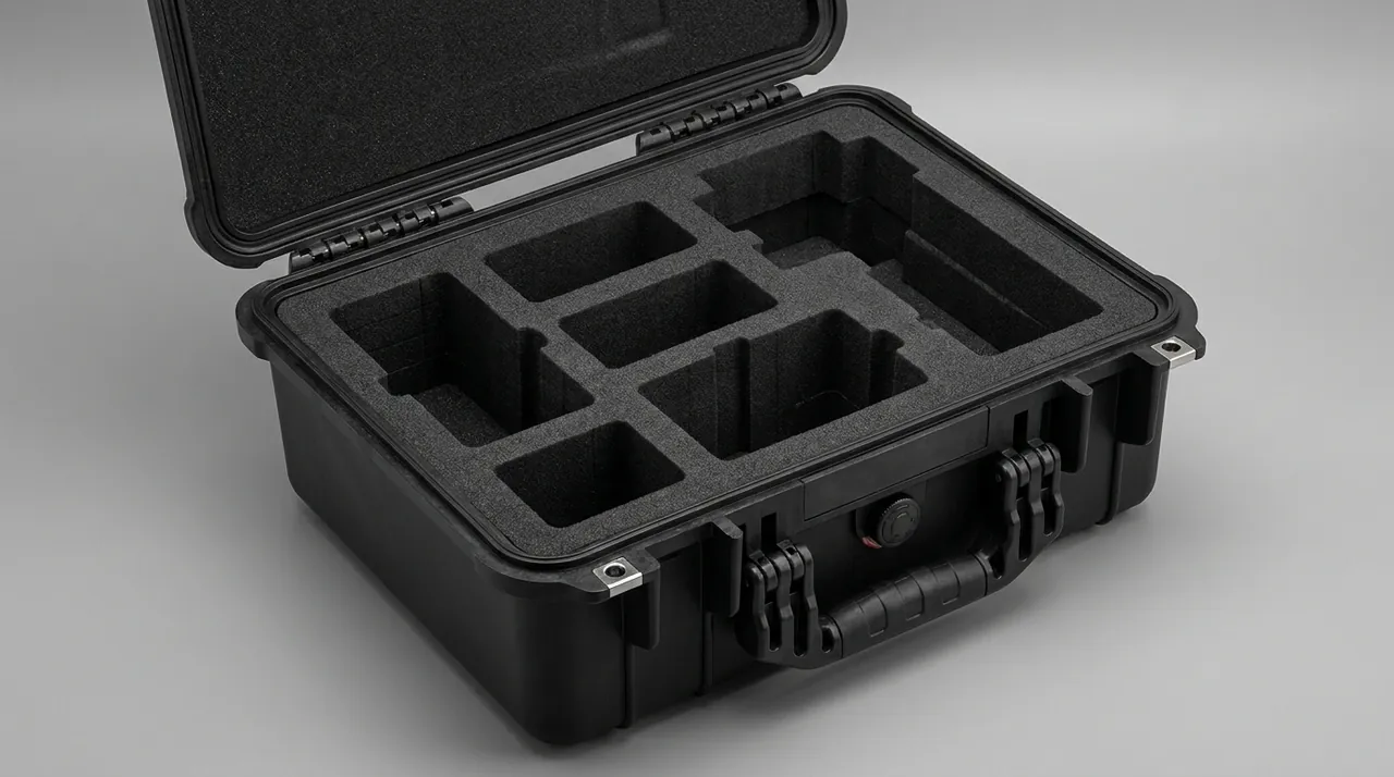
Glass impact strength falls at low temperature. Impact toughness is temperature sensitive, and the brittle transition region moves closer to room temperature as temperature drops, so cold conditions make spontaneous failure more likely. This is an inherent property of glass packaging; no case can eliminate it. The achievable goal is to keep impact energy below the allowable input by controlling buffer thickness and vibration transmission.
Seal Shrinkage and Recovery Under Cold Chain Conditions
A number of wine bottling lines sit in underground cellars or low-temperature pre-cooling rooms. Parts may be packed at 8 to 12 degrees Celsius and then loaded into a summer trailer where case interiors exceed 45 degrees; other lines ship straight from a cold store to a southern plant in winter.
Thermal contraction and recovery of elastomer seals is the most overlooked failure mode on the list. EPDM has a coefficient of thermal expansion around 1.7 times ten to the minus four per kelvin. Going from 10 to 45 degrees Celsius is a 35 kelvin step, so a 100 mm dimension grows roughly 0.6 mm freely. Tolerance bands inside a valve chamber are often only a few tenths of a millimetre, and 0.6 mm of growth is enough to turn a designed interference into a rigid bind.
Worse is irreversible contraction. After cold exposure, some elastomers lose rebound capacity as plasticiser migrates and crosslink structure relaxes. The ring still sits in the chamber and still looks correct, but compression force has dropped and the seal leaks. Only on-site recalibration reveals it.
Three layers of countermeasure.
Structural. Design seal compression at 20 to 25 percent and allow more than 2 mm of free travel in the cavity, so thermal growth never becomes rigid interference. The compartment design must leave seals loose in the box, never pinched by foam.
Material. Choose grades with good low-temperature rebound. Higher 1,4-hexadiene content improves low-temperature flexibility in EPDM. For harsher duties, use HNBR or a combined EPDM and silicone structure.
Process. Do not start the machine immediately on arrival. Warm the part in the assembly room for 8 to 12 hours at ambient, run the leak test, then calibrate stroke. Warming time belongs in the installation manual. Cold-chain case configuration is covered in cold chain food transport cases.
Splash and Cross-Contamination Control at Adjacent Stations
A bottling line is a sequence of stations: depalletise, wash, fill, cap, label, case pack. The valve and the capping head sit in the middle, with the washer directly upstream and the labeller directly downstream. Both neighbours shape the protection requirement.
From the washer. The drip section at the washer exit throws high-pressure mist and stray droplets. Detergent droplets landing on a valve seat mix with residual sugar to form an acidic film. A single exposure will not corrode stainless steel, but repeated exposure nucleates pitting at the seat edge. Protection requires a splash guard on any storage of valves near the filling station; valves must never sit open on a bare rack.
From the labeller. Label liner and paper debris are potential cross-contamination sources. Wine microbiology is sensitive to foreign adhesives and paper fibre. Once a mouth is contaminated, later inspection can fail on microbial limits.
From the conveyor. Debris and metal particles abraded by bottle bases on the conveyor table land on the open mouth and go straight onto the sealing surface.
Combined, these risks define a packing preparation sequence. Wipe the part at the filling station using a spray-and-wipe method, not compressed air, allow 30 minutes to drain naturally, then move to the dry room, and finish with a white-cloth inspection before sealing. Put a physical partition between labelling and filling, taller than the bottle mouth plane. For isolation practice on this kind of line, see food processing line cases.
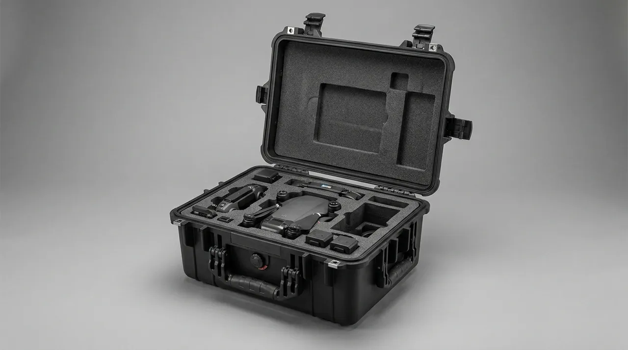
The splash guard must be food-grade PP or PET clear sheet. Ordinary plastic sheet slowly releases odour under dilute detergent mist, and that odour migrates into the valve chamber as a taint risk.
Compartment Split Foam Against Liquid Slosh and Shock
Wine is liquid, and liquid in a bottle generates a sloshing impulse whenever the case moves. Vibration between bottles, impact between bottle and case wall, and the whole case rocking on the truck combine so that the resultant force at the mouth is not small.
The analysis is straightforward. Once foam confines each bottle in a moulded pocket, excursion is limited, but shock acceleration is not. Force is roughly mass times acceleration. A 750 mL bottle with glass and wine weighs about 1.3 kg; at a 3 g shock the instantaneous resultant is close to 38 N. Acting on a flange area of roughly 15 square millimetres, that is an equivalent stress near 2.5 MPa, already approaching the fracture strength of poorly annealed glass.
The goal at the mouth is therefore to hold acceleration below 2 g, not to rely on foam hardness.
Four measures follow.
- Confine with moulded pockets, not loose fill. Cut EPE to match the bottle profile, with about 15 mm of foam around the body and an extra 8 mm collar around the neck.
- Limit free space. Size the interior 20 mm larger than the largest bottle group envelope, and fill that 20 mm with foam. Excess clearance gives bottles a long excursion and therefore a high impact energy.
- Break cavity resonance. A rigid shell plus foam plus trapped air forms a low-frequency standing wave. Two foam grades of differing density stacked together scatter that resonance.
- Pack valves and heads in separate cases. Valve assemblies resist point impact, bottles resist sustained compression. Mixing them forces the design to the stricter of the two, which wastes both weight and volume.
For foam selection see EPE versus EVA foam and foam material comparison. For the trade-off between dividers and a full foam bed, see dividers versus foam.
Metering Accuracy Verification Before and After Packing
Accuracy verification is the most important deliverable in this protection scheme. A case built well still has no value if it cannot prove it protected the metering performance.
Before packing, establish the baseline.
- Calibrate the valve three times at 20 degrees Celsius using deionised water or a standard wine base. Take the mean as the baseline and record the range of the three runs. If the range exceeds one third of the tolerance, calibrate and adjust the valve first, then recalibrate.
- Record valve serial number, calibration date, operator, ambient temperature, liquid temperature, set pressure, and calibrated volume.
- Test capping bite with ten bottles from one batch through the same head, measuring leak rate and peel force. The peel force floor for glass is 60 N, and the leak rate target is zero.
- Photograph the needle-to-seat contact line as a visual baseline.
After packing, before sealing.
- Use a clear inspection cover so the part stays visible, confirming the foam pocket matches the part contour with no suspended gap.
- Verify case closure mechanically: apply load at both ends and listen for anomalies.
- Shake test: 20 cycles laterally, 20 vertically, then open and check for displacement, noise, or loosened fittings.
On arrival, re-verify.
- Read the shake record card before opening.
- Warm the part in the assembly room for 8 to 12 hours after cold transport.
- Re-run fill calibration; deviation must sit inside the original baseline tolerance.
- Cap 20 bottles and confirm zero leak rate with peel force in spec.
Store all three data sets and deliver a metering performance transfer card with the case. Without that card, an accuracy dispute cannot be assigned. The logic follows the same sequence used for incoming waterproof inspection: read the record, open the case, then re-verify.
Overland Vibration and Stack Load for Complete Line Assemblies
Overland vibration must be graded according to how the parts are actually packed.
Precision items such as filling valves and capping heads normally travel as small, high-count cases: one valve per cavity, two to four valves per outer case, and several cases consolidated onto a pallet. One failure then takes no neighbours with it, and pallet stacking spreads the load onto upper cases rather than onto a single box.
For road transport the vibration input comes mainly from surface irregularity, tyre and suspension behaviour, and braking and acceleration. The standard route is a transport test series under GB/T 4857, or cyclic vibration at the DC-13 or DC-15 level of ASTM D4169. The acceptance criterion is not that the case survives. It is that the part baseline is unchanged after opening.
Stack load has to be tied to the logistics plan. Three to five layers is typical, and stacking has to match pallet size, stacking method, and warehouse ceiling height. Three points matter.
One, load direction. Stacking load pushes down; valves fear lateral shock. Foam creeps slowly under sustained load, and once compression exceeds the design value by 20 percent the pocket loses fit and the part gains excursion space in transit. EPE handles long-term stack load better; EVA absorbs impact better but creeps sooner. See EVA foam advantages.
Two, contact with the floor. Bottom cases take the full stack load and see the highest foam compression. Give bottom cases an independent load-bearing layer separate from the lateral cushioning.
Three, time scale. Short-term staging and six-month warehouse storage are different requirements. Long-term storage needs a creep calculation, or a note on the packaging stating that cavity thickness must be re-verified after a stated number of months.
Transport environment records should also ship with the case: dispatch date, transport mode, and temperature conditions en route. Winter cold movement in particular tells the receiving plant how long to warm the parts.
Arrival Acceptance: Leak Down, Pressure Drop, and Bite Sampling
Arrival acceptance closes the protection loop. Its purpose is to confirm that transit did not change a functional parameter.
Appearance and records. Match case number, part number, calibration record, and seal record. Check whether sealing tape has been lifted and resealed; a tamper-evident strip is the simplest deterrent. Look for water staining, dents, or bulges in the shell.
Gas tightness. For the valve chamber, block the inlet and outlet, charge the chamber to 1.5 times working pressure, hold five minutes, and require pressure drop of no more than 2 percent. For the head air circuit, hold ten minutes and require no more than 5 percent drop. Any exceedance means the seal was extruded, over-compressed, or has failed.
Needle stroke. Measure the extreme position of the needle at full open with a feeler gauge or stroke rule and compare it against the calibration record. Deviation beyond the set value means recalibration.
Crown cap bite sampling. Draw twenty bottles at random, cap them on the arriving head, leak-test every bottle, and peel-force test five of them.
Fill volume re-verification. Run ten calibration cycles under the baseline conditions. Inside tolerance means pass.
Case disposition. Once gas tightness passes, do not break the case down for storage. Keep it as the container for in-plant movement and redispatch. Selection for in-plant transfer cases is covered in toolbox internal foam selection.
File the transfer card after acceptance and record the remaining number of uses for that case type. Assess cavity thickness after three to five long-haul trips; below 75 percent of design, replace the liner rather than continue. For replaceable liner design see custom foam insert guides.
Frequently Asked Questions FAQ
Q: Must filling valves be cleaned before packing, and what is the risk of skipping it?
A: Yes, cleaning is mandatory. Residual sugar and fructose syrup dry into a hard crystalline layer on the seat sealing face, the needle shoulder, and the piston chamber. That layer has irregular geometry, so on reassembly the seat cannot guarantee a continuous sealing line and fill accuracy drifts from plus or minus 0.5 percent to plus or minus 2 percent. A second risk is that fragments break free in transit and travel inside the chamber as abrasive particles against the needle-to-seat fit, which then wears the guiding bore and shows up later as unstable stroke. The recommended sequence is two circulation passes of 60 degree Celsius food-grade neutral detergent, a 40 degree Celsius rinse until foam-free, then drying until no water film remains inside. Never use chlorine-based cleaner, because chloride ions pit 316L stainless steel and the resulting pits become the next harbour for residue. Finish with a lint-free white cloth wiped in one direction along the seat face. Even then, trace residue remains, so add a 60 micron food-grade PE barrier bag to stop residual wine from being wicked into the EPE foam.
Q: Why can filling valves and crown caps not travel in the same case?
A: Three separate reasons. First, media and odour risk: the punching oil and edge burrs on a steel cap strip can touch the valve sealing face, and residual wine dissolves trace anti-rust oil from the strip, producing both odour and contamination. Second, geometric conflict: a crown cap is a 29 mm thin steel part while a valve has protruding chamber fittings and air ports, so if both sit loose in one cavity the cap acts like a blade across the valve body during vibration. Third, different packaging logic: caps need flat abrasion-proof packing, while valves need a suspended cavity that keeps them clear of impacts, and no single case geometry delivers both. Where co-transport is unavoidable, use a rigid divider, place the full cap carton on the upper layer, and keep at least 30 mm clearance above the valve cavities. Add a desiccant to the cap layer only, never to the valve layer, since the cap compartment is dry and the valve chamber must stay free of trapped moisture.
Q: Do filling valves on the same batch have to share metering accuracy, and what happens if batches are mixed?
A: They must. Line accuracy is the statistical result of every valve on the line. If calibrated volumes disperse too widely, the batch mean drifts even when each valve sits inside its own plus or minus 1 percent tolerance, and incoming QC rejects the whole batch. Dispersion also changes the tuning of the whole line: operators compensate for the average, so the valves at the tight end of the spread then run persistently over or under target once a correction is dialled in. The more serious consequence is traceability: once a batch deviation appears, nobody can tell whether one valve drifted or the whole line shifted, and the investigation cost climbs sharply. A twelve thousand bottle complaint, for example, has to be traced valve by valve before any corrective action can be justified. Buy, calibrate, and pack same-model valves as a set, and record calibrated volume, set pressure, deviation direction, and calibration date per valve in the case configuration file. Set packing keeps same-cavity parts comparable, so if one unit does behave differently, the file identifies it immediately.
Q: After cold transport, must parts return to room temperature before startup?
A: Yes, and immediate startup is not recommended. Elastomers such as EPDM stiffen when cold, so initial compression force is higher than design, and low temperature reduces rebound capacity; some grades suffer irreversible relaxation. Starting straight away can produce slow or sticking needle motion, and a leak test taken at that point does not represent the working condition. A cold part may also pass a leak test at the shop floor and then leak on the line once the line runs warm, which is an expensive way to discover the problem. Warm the part at ambient in the assembly room for 8 to 12 hours, determined by the gap between transport temperature and assembly room temperature; for a winter shipment leaving a minus 10 degree cold store and arriving in a 25 degree room, allow at least 16 hours. Warm naturally rather than with forced hot air, which can distort seals locally. Run the leak test and stroke calibration only after warming, and put the warming duration in the installation manual.
Q: Should the capping head regulator be locked before dispatch?
A: No. The goal is a reproducible calibration value, not a regulator frozen in place. A locknut left tightened can creep slowly under long-haul vibration, so the reading on arrival drifts and there is no way to tell whether the drift came from the locknut moving or from another cause. The consequence is a capper that appears calibrated and quietly under-drives every bottle it seals, which is exactly the batch-level bite failure that a per-bottle check will miss. Do it in three steps instead. First, record each actuator cylinder regulator value in bar to one decimal place before dispatch. Second, add a physical stop: mark the knob with paint, or fit a locking nut with a graduated sight window. Third, write the pressure value into the case configuration file and reproduce it on the unloaded air circuit before fitting bottles. Check the regulator diaphragm as well, since a diaphragm damaged in transit reads low at the gauge but delivers less force at the head. Cover air ports with dust caps and protect the cylinder and hose fittings in their own small cavity.
Q: When cap leakage rates run high, is transport necessarily the cause?
A: Not necessarily, so separate process problems from part problems first. If every bottle from one head leaks, the cause sits in the capping process: check whether pressure reaches specification, whether the compression stop is correct, and whether the flange itself is acceptable. If a single bottle behaves differently with a different head, or the same head behaves differently on a new bottle, then suspect transport damage to the head. The signature of transport damage is a deformed press face producing uneven distribution of capping force, which shows up as leakage on one side rather than all around; check press-face squareness against the axis with a feeler gauge, and look for a bent head shank or a scored guide bore. Also rule out a common misdiagnosis: a crown cap that fails to bite leaks even when the head is perfect. Cross-test new and old bottles to separate the two. Send the transport record and seal photographs with any claim, because without them a transport dispute has no basis for judgement.
Q: Why must bottle mouths ship in a single layer?
A: Because the failure mode at the flange is sustained compression, not point impact. The glass flange is already loaded by 0.3 to 0.5 bar of internal pressure, and capping applies a reverse force. Stacking an upper case on top of the mouth adds a longitudinal compression through the partition, which activates tensile stress in the neck region; if the bottle is poorly annealed or already micro-cracked, transport vibration drives that crack forward. The bottle can look perfect on arrival and then leak or burst spontaneously after days or weeks on a cold-chain shelf, which is why the failure is so often blamed on the glass supplier instead of the packaging. So mouths ship single-layer, with the mouth plane parallel to the case wall, EPE partitions between layers, and no partition hole aligned with a mouth, because a hole lets the neck drop through and take load directly. Where the line needs higher packing density, use a neck-cradle pallet instead of squeezing the case interior.
Q: How many times can the case be reused, and how do we know the liner is spent?
A: Design life is typically three to five long-haul trips, or about two years of normal service. Estimate by duty: three trips for long-haul road transport, five for in-plant transfer only. Foam degrades by two mechanisms at once: repeated shock cycles cut the cell structure into fines that shed into the cavity, and sustained stack load slowly compresses the same cells so the pocket loses its fit. Three methods tell you when to change the liner. First, measure remaining foam thickness at key cavity points with calipers and compare against design; below 75 percent, replace. Second, inspect the surface for permanent indentation, cracks, crumbling, and any sign of EPE shedding. Third, run a functional re-verification: put a calibrated part back in the old case, run the shake test, and if the calibrated value drifts out of tolerance the cavity has lost its constraint. Liner replacement needs no new shell; only the foam bed changes, because an ABS or PP shell normally outlasts the liner many times over.
Conclusion and Related Reading
These are functional modules, not rugged metal parts. JUNZHIJIA builds cases on that principle, with custom moulded inserts, OEM/ODM, and case documentation from Kexin New Materials (Guangdong) Co., Ltd.
Related Reading