

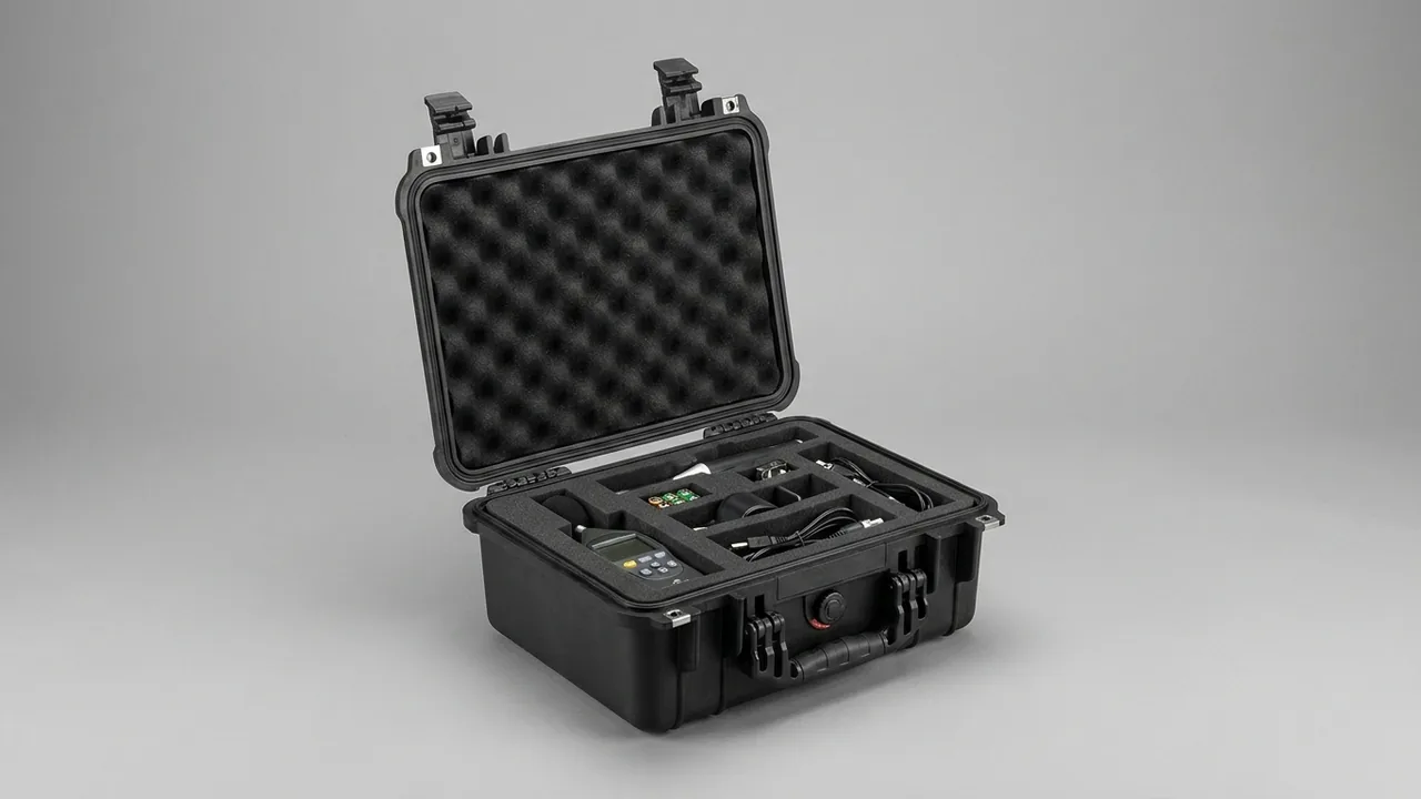
A documentary crew collects its kit at the airport and finds fine marks around the lens mount of the main body, and one of three prime lenses noticeably stiffer on the focus ring. The case itself is undamaged and the drop was less than half a metre. The problem was inside: the body and lens shared one compartment with nothing but a thin cloth between them, and three days of transport vibration let them grind against each other. Photography equipment rarely fails because the case broke. It fails because of relative movement inside the case, trapped moisture and repeated micro-vibration — processes that are invisible when the lid opens and only appear later as drifting focus, odd noises or mould.
JUNZHIJIA states the design principle for camera cases as follows: protection must be judged by the most fragile interface of the equipment, not by the strength of the case. For a lens, that interface is the mount and the barrel; for a body, it is the mount seat, the screen and the hot shoe; for the system as a whole, it is the sensor and its coatings. The liner must identify each of these interfaces and give each one dedicated support and separation, while the shell only has to keep external load outside.
Table of Contents
- Failure Modes of Photography Equipment and Protection Targets
- Shell Construction: Choosing Between Injection PP and Rotomoulded LLDPE
- Physically Separating Lens and Body: Mount and Element Protection Logic
- Compartment Liner Design: Die-Cut EVA and Pre-Cut Foam
- Drop Protection: Allowable Acceleration and Cushion Thickness
- Transport Vibration and Long-Term Micro-Motion Wear
- Moisture, Mould and Sensor Cleanliness
- Managing Batteries, Memory Cards and Small Accessories
- Airport Screening and Carry-On Strategy
- Access Flow and Single-Operator Efficiency
- Temperature and Humidity Shock Across Shooting Locations
- Stacking, Vehicle Loading and Multi-Person Crews
- Acceptance Criteria, Maintenance and Custom Delivery
- Frequently Asked Questions FAQ
- Conclusion and Related Reading
Failure Modes of Photography Equipment and Protection Targets
Photography equipment is best classified by interface rather than by component. The mount interface carries bending moment and shear, and its typical failures are a slightly deformed mount seat, worn contacts and drifting focus accuracy. The barrel interface carries radial compression, and its typical failures are changed focus ring damping and uneven zoom feel. The filter interface carries edge impact, and its typical failure is a deformed filter ring that can no longer be unscrewed. The sensor and coating interface carries moisture and particles, and its typical failures are mould, hazed coatings and dust adhesion. The screen and hot shoe interface carries point load, and its typical failures are screen marks and displaced hot shoe contacts. Once failures are grouped by interface, the liner brief becomes clear: give each interface a local environment free of bending moment, free of compression and free of foreign contact.
| Interface | Main load | Typical failure | Liner response |
|---|---|---|---|
| --- | --- | --- | --- |
| Mount | Bending, shear | Deformed seat, worn contacts | Recess at mount, body supported from base and sides |
| Barrel | Radial compression | Changed damping, stiff zoom | Ring-shaped cradle, never point contact |
| Filter ring | Edge impact | Deformed ring | Filter end recessed 5–10 mm |
| Sensor and coating | Moisture, particles | Mould, haze | Desiccant plus clean liner |
| Screen and hot shoe | Point load | Screen marks, shifted contacts | Lid clearance or soft pad |
One judgement is often missed: the protection rating of the case only decides whether the outside gets in, not whether the contents damage each other. An IP67 case that puts a body and a lens in the same compartment stops rain but not vibration grinding. Evaluation should therefore start with compartment layout and support faces, then move to sealing and shell.
Shell Construction: Choosing Between Injection PP and Rotomoulded LLDPE
Shell choice for a camera case follows the transport mode rather than the price of the equipment. Where carry-on use dominates, the shell must control weight and external dimensions, and injection-moulded PP or ABS both work: PP has good chemical resistance and uniform walls and suits a regular ribbed case, while ABS offers the best appearance accuracy for finished cases but yellows under prolonged ultraviolet exposure. Where vehicle transport, checked baggage and field work dominate, rotomoulded LLDPE is stronger — seamless, 4 to 6 mm thick, tough down to −40 °C and resistant to brittle cracking on cold-weather shoots, at the cost of more weight and higher unit price.
Whichever process is used, three structural details must be checked. First, the double radius at each corner: the outer radius spreads impact and the inner radius reduces foam cutting difficulty and stress concentration. Second, continuity at the hinge seats, because hinges take the most repeated loading in the whole case and their ribs must connect through to the side wall. Third, internal wall flatness, since an uneven inner wall prevents the foam from seating and creates local voids where moisture collects and equipment shifts. Internal bosses, print steps and mould parting lines should be held within 1 mm or given corresponding relief in the liner.
| Process | Typical transport | Advantage | Limitation |
|---|---|---|---|
| --- | --- | --- | --- |
| Injection PP | Carry-on, car | Uniform walls, controllable cost | Needs modification for cold |
| ABS | Carry-on, commercial work | Best appearance accuracy | UV yellowing |
| Rotomoulded LLDPE | Checked, field, cold regions | Seamless, low-temperature toughness | Heavier, moderate precision |
| Aluminium frame composite | High-value kits | Stiff, repeatedly resealable | Expensive, heavy |
For most photography crews the sensible arrangement is two cases: an injection case for carry-on duty and a rotomoulded case for field work. If only one can be kept, choose for the worst leg of the itinerary rather than the most frequent one.
Physically Separating Lens and Body: Mount and Element Protection Logic
Whether lens and body are separated is the single most important decision in camera case design. Combined storage is faster to access and takes less space, but the mount carries a bending moment and the body weight passes through the mount into the barrel, so any vibration produces a small oscillation at the mount. Separate storage leaves the mount unloaded and gives each item full support, at the cost of 15 to 25 percent more space and one extra assembly step on site.
The engineering basis for the choice is the weight ratio and mount stiffness. When the lens is heavier than the body, combined storage moves the centre of gravity toward the barrel and sharply increases the bending moment at the mount under vibration, so separation is safer. When body and lens are comparable in weight and the mount is metal with a locking pin, combined storage is acceptable for short trips, but the front of the lens still needs a support point rather than hanging from the mount alone. Long telephoto lenses should always travel separately, with a cradle at the barrel midpoint and another at the front, turning a cantilever into a multi-point support.
Filters and hoods are easily forgotten secondary interfaces. With a filter fitted, its ring protrudes beyond the barrel, so lateral impact transfers straight into the filter ring and the front element group. The liner should provide 5 to 10 mm of relief at the filter end so the liner takes the impact first. Where a reversible hood is used, it should not press too tightly against the barrel after reversal, because sustained pressure loosens the bayonet. On the body side, pay attention to the screen and hot shoe: orient the screen inward or upward so it never takes a point load, and remove any hot shoe accessory before transport, since the solder joints of hot shoe contacts are far weaker than the insertion force they see.
Compartment Liner Design: Die-Cut EVA and Pre-Cut Foam
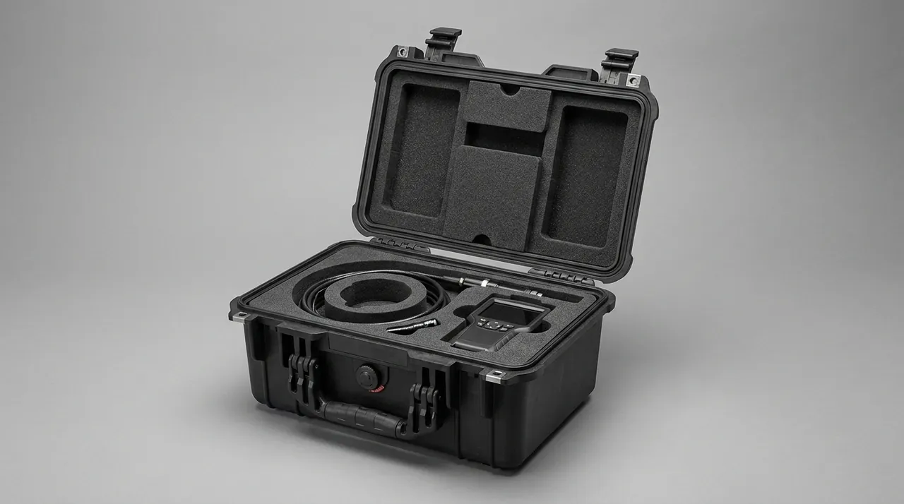
Camera case liners are built in three ways: fully CNC die-cut EVA, pre-cut grid foam, and a combination of the two. Fully die-cut EVA gives the highest positioning accuracy, with every compartment machined to the equipment outline and large contact areas at the base and walls that suppress micro-motion; the drawback is high tooling or programming cost, and an old liner rarely suits replacement equipment. Pre-cut grid foam is the most flexible, letting users remove squares to form compartments; the weakness is that cell walls are column-shaped supports with small contact areas that collapse at the edges over time, and every cell is the same depth, so layered support for a lens is difficult.
The combined approach is the most practical: 20 to 30 mm of EPE or IXPE at the base for absorption and levelling, die-cut EVA in the middle for location, a thin EVA or felt layer on top for surface protection, and replaceable support blocks at the corners of the body compartment. This keeps positioning accuracy while leaving room to adapt when equipment changes — swapping one lens means remaking that single middle compartment rather than the whole insert. Compartment size follows the equipment outline plus an interference allowance, typically 1 to 2 mm per side. Because lenses are bodies of revolution, a ring-shaped cradle with even circumferential contact is preferable to two-point support, which turns into a see-saw under vibration. Foam density and compression set strongly affect long-term positioning, and the full material comparison is set out in case foam material comparison, the pre-cut foam insert use cases and the EVA foam insert custom process.
| Liner approach | Positioning accuracy | Rearrangeable | Unit cost | Best fit |
|---|---|---|---|---|
| --- | --- | --- | --- | --- |
| Fully die-cut EVA | Highest | Low | High | Fixed equipment set |
| Pre-cut grid foam | Medium | Highest | Low | Frequently changed kit |
| EVA plus EPE combination | High | Medium | Medium | Most photography crews |
| EVA plus removable dividers | High | High | Med-high | Varied shooting tasks |
Drop Protection: Allowable Acceleration and Cushion Thickness
Drop protection in a camera case cannot be solved by adding foam thickness; it has to be calculated from allowable acceleration. The shock acceleration a body or lens can survive depends on its internal construction and component mass: bodies tolerate vertical acceleration reasonably well, but models with stabilisation assemblies are more easily displaced by lateral shock, while lenses tolerate axial shock better than radial shock, particularly externally zooming designs and telephotos with moving element groups. The engineering approach is to work back from the component's allowable acceleration to the cushion thickness, not the other way round.
A simplified energy method works well: convert drop height to landing velocity using v equals the square root of 2gh, then find the minimum braking distance from s equals v squared over 2a. Dropping from 1 m gives a landing velocity of about 4.43 m/s; at an allowable 40 G, roughly 392 m/s squared, the required braking distance is about 25 mm. That means 20 mm of foam is not sufficient at a 1 m drop, and 25 to 30 mm is a reasonable starting point. This is a single-direction estimate only; real cases also deform, foam compresses in stages and contact occurs at several points, so engineering practice adds 20 to 50 percent margin and confirms it with physical drop testing.
| Drop height | Landing velocity | Braking distance at 40 G | Braking distance at 60 G |
|---|---|---|---|
| --- | --- | --- | --- |
| 0.5 m | 3.13 m/s | About 12.5 mm | About 8.3 mm |
| 0.8 m | 3.96 m/s | About 20 mm | About 13.3 mm |
| 1.0 m | 4.43 m/s | About 25 mm | About 16.7 mm |
| 1.5 m | 5.42 m/s | About 37.5 mm | About 25 mm |
Drop verification should follow the relevant ISTA or GB/T 4857 procedure, with accelerometers inside the case to confirm the peak actually transmitted to the equipment. For high-value kits, two-stage cushioning is safer: the main liner absorbs, and an independent elastic pad at the base of each compartment consumes high-frequency shock locally. Shock and sealing are structurally coupled, because a hard impact deforms the case and misaligns the sealing faces, so both must be verified together, as covered in combined shock and seal design and shockproof toolbox solutions for precision tools.
Transport Vibration and Long-Term Micro-Motion Wear
Unlike a drop, vibration is a low-amplitude, long-duration, cumulative load, and it fails parts not in one event but by letting two contact surfaces grind against each other for hours. In photography equipment the classic sites are the mount face where it meets the rear element group, the threaded joint between body and tripod plate, and any point where an accessory touches the case wall. The result is usually lost precision rather than lost function, which makes it hard to detect immediately after a trip.
Suppressing micro-motion rests on removing clearance and reducing relative slip at contact faces. Three measures follow. First, the liner must support each item at two or more points, and those points should straddle the centre of gravity so the item cannot rock inside its compartment. Second, anything movable — handles, tripod plates, reversed hoods — should be locked or removed before packing, reducing the degrees of freedom available. Third, for heavy items with regular shapes, an elastic compression face inside the compartment keeps the item lightly loaded when the lid is closed, raising contact stiffness. Compression is not better the higher it goes: excessive load causes permanent foam deformation and destroys the very preload it was meant to provide.
Vibration verification can reference the ISTA random vibration procedures or the GB/T 4857 vibration test, with two measures of interest: how far the equipment moves inside its compartment, and how much the critical surfaces wear. A simple and effective acceptance check is to apply a removable marker strip to the equipment housing and inspect after transport whether the marker has shifted. For shoots that involve long hours on rough roads, adding a third support point to the body compartment converts two-point support into three-point support and markedly improves stability.
Moisture, Mould and Sensor Cleanliness
Mould is the most insidious enemy of photography equipment. Spores are everywhere, and they grow readily above 60 percent relative humidity at 20 to 30 °C with poor ventilation, feeding on the organic components in lens coatings. Once mould has formed it etches into the coating and is difficult to remove completely even with professional cleaning, and it degrades contrast and flare performance. Preventing mould is a humidity management problem, not a cleaning problem.
Three levers govern humidity inside the case: sealing, desiccant and monitoring. Sealing sets the ingress rate, and a compliant gasket with adequate compression points is the prerequisite; an aged gasket loses moisture resistance quickly, with criteria covered in case seal ageing and outdoor case seal ring selection. Desiccant is sized to net internal volume, typically 10 to 20 g of silica gel per 10 L, and cases holding leather, textile or wooden accessories consume it faster, so allowance should be increased. Monitoring is the step most often skipped and it costs almost nothing: fit a humidity indicator card graduated from 10 to 60 percent, read it before unpacking, and treat a reading above 40 percent as a signal to change desiccant or inspect the seal.
Cleaning addresses the sensor and optical surfaces. Most sensor dust inside a case originates from liner fibres, foam debris and clothing lint, so closed-cell materials that shed little should be preferred, and felt, cotton and open-cell foam should never be used as direct contact surfaces. Lens changes should be done in a controlled environment where possible; in the field the case itself can be used as a shelter, with the lid open as a windbreak so the change happens inside the case. Cleanliness requirements for precision instrument cases are covered in precision instrument protective case design.
Managing Batteries, Memory Cards and Small Accessories
The items most casually packed in a camera case are often the riskiest: lithium batteries, memory cards, wireless transmitters and adapter rings. Batteries bring short-circuit and thermal runaway risk, memory cards bring loss and data damage risk, and adapter rings bring thread and mount deformation risk. The rule for small items is fixed position, physical separation and quick auditing, not "put it in whatever gap is left".
Battery handling has explicit requirements. Each battery needs its own well, individual packs should be separated by insulating dividers, and contacts should carry dust caps or insulating covers so they cannot complete a circuit against metal parts. The battery well should sit low in the case when it stands upright, because batteries are dense and a high position gives them extra throwing energy in a shock. Memory cards are best held in a dedicated card unit with separate slots, and the inside of the lid can be divided into used and unused zones so that switching on set does not cause confusion — a point that matters particularly for multi-camera shoots.
| Small item | Risk | Compartment requirement | Extra measure |
|---|---|---|---|
| --- | --- | --- | --- |
| Lithium battery | Short circuit, thermal runaway | Own well, packs separated | Contact protection, insulating caps |
| Memory card | Loss, data damage | Dedicated slots, used or unused | Lid-mounted card unit |
| Transmitter and wireless module | Broken antenna, damaged port | Antenna removed and stored apart | Anti-static bag |
| Adapter rings and filters | Thread or ring deformation | Dedicated round slots, no stacking | Relief at end faces |
| Cleaning tools | Liquid leak, fibre shedding | Separate washable well | Sealed bag with absorbent layer |
The ideal on site is that the case is ready on opening: body and main lens in the upper layer, batteries and cards in a separate middle tier, spare lenses and lighting in the lower tier. That hierarchy lets a single operator change lens and battery without shifting other items, which reduces the number of times equipment is set down and therefore the number of chances it has to be dropped.
Airport Screening and Carry-On Strategy
The screening problem is not the case but which items must travel with the passenger. Lithium and spare batteries must be carried in the cabin and cannot be checked; equipment containing batteries that must be checked should be designed so the cells detach quickly. Some airports also enforce cabin weight and size limits strictly, and professional camera cases often sit right at the threshold, so cabin size and weight limits should be treated as hard constraints at the selection stage rather than discovered at the counter.
Carry-on strategy also involves layered access. Items most likely to be pulled out for separate screening should sit where they can be removed easily, while the main equipment stays in the case. The liner should therefore make its removable layers independent modules, so a screening inspection does not require disturbing the whole case. Where a small quantity of liquid such as lens cleaner must travel in the case, use a container within the permitted capacity and place it in a sealable liquid well so a leak cannot contaminate the liner.
| Item | Checked allowed | Suggested position | Note |
|---|---|---|---|
| --- | --- | --- | --- |
| Body with battery | After removing the battery | Carry-on preferred | Design for quick battery release |
| Spare lithium batteries | Not allowed | Dedicated battery well | Contacts insulated |
| Lenses | Allowed | Ring cradle, separate compartments | Telephotos carry-on preferred |
| Transmitter and wireless module | Allowed | Antenna removed and stored apart | Anti-static packaging |
| Cleaning liquid | Depends on volume | Separate liquid well | Sealed with absorbent layer |
Sealing also plays a role here. A carry-on case mainly faces rain and splashes, where IP65 is usually enough; where the itinerary includes boat transfers, water crossings or wet-season field work, IP67 is safer. The basis for the rating difference is explained in differences between IP65, IP66 and IP67 and how to verify IP67 certification.
Access Flow and Single-Operator Efficiency
The efficiency bottleneck in photography is rarely the shooting; it is changing lenses and batteries. On a single shoot a photographer may open the case more than twenty times in two hours, and if every battery change requires moving an upper layer out of the way, the cumulative time cost and equipment exposure both rise measurably. Liner design must therefore consider access flow: high-frequency items belong where the lid reveals them immediately, and low-frequency items can sit deeper.
Three rules shape good access flow. Single-hand reach means high-frequency items sit on the operator's side once the lid is open and do not need a second hand to hold the lid. Blind identification means compartments for different items differ clearly in shape, so a dark location still allows positioning by feel. Unique landing means each compartment corresponds to exactly one item, with no design where the wrong item also fits. Blind identification is the most often missed: many liners make every compartment an identical rounded rectangle for visual tidiness, so users must look down and identify each slot every time.
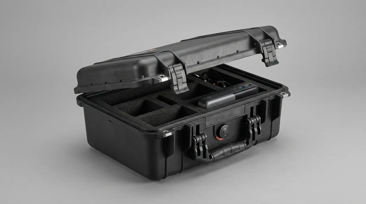
Multi-person crews need handover points as well. When equipment passes between photographer, assistant and kit manager, fixed liner positions become the audit list. A layout diagram on the inside of the lid, combined with numbering on each item, turns handover into a check against a drawing. The diagram matters most for spares, since spares are the items most likely to go missing within a team. Removable divider systems are valuable for crews that adjust loads often, and the trade-off is discussed in outdoor case inner cushioning and cushion liner selection.
Temperature and Humidity Shock Across Shooting Locations
The biggest risk on cross-climate shoots is not sustained high humidity but rapid change. Moving from an air-conditioned room into humid outdoor air condenses water on the case immediately; walking from a cold dawn into a warm room makes the equipment inside the condensation surface. For optics, the condensed film attracts airborne dust within minutes and leaves water marks that are hard to remove. For bodies, condensate seeps into gaps and corrodes circuits over time.
The response has three levels. Operationally, do not open the case immediately after a temperature change; let it stand in the target environment for one to two hours so internal and external temperatures converge. Managerially, record the humidity indicator reading each time the case is opened, so trends replace single data points. Technically, sealing plus desiccant holds internal humidity below 40 percent. One point deserves emphasis: the better the seal and the more desiccant present, the more likely an internal cold surface becomes, because internal air lags behind external warming and equipment surfaces stay below the dew point. Standing time is therefore never optional.
For work that involves frequent transitions, a two-case strategy helps: one case for transport, sealed and with desiccant, and one small case for on-site work that opens and closes quickly. This reduces exposure time on set without compromising transport protection.
Stacking, Vehicle Loading and Multi-Person Crews
Camera cases rarely travel alone; they are stacked with other equipment cases in vehicle boots, equipment trucks and air containers. Stacking loads can exceed expectations: a 25 kg case stacked four high puts about 75 kg on the top face of the lowest case. The structural responses match general protective cases — ribbed top face, thickened corners, anti-slip base — but camera cases add one requirement: the top face must not develop local dishing, because dishing transfers through the liner as compartment deformation and changes the preload on equipment. Camera case top faces therefore need more stiffness than a toolbox of the same size.
Vehicle restraint should limit movement rather than apply pressure. Common practice includes load straps, a boot partition net, and strap holes in the base. One warning: never cinch a belt tightly around the middle of the case to secure it, because sustained side wall compression causes creep and degrades sealing face flatness. The correct approach constrains the degrees of freedom of the case without clamping it. General principles for stacking and stackable design appear in toolbox stackable design benefits and stacking height limits.
Acceptance Criteria, Maintenance and Custom Delivery
Acceptance should be a written checklist with retained records. For appearance, check for through-wall cracks, dished corners and scratches in the seal groove. For function, check consistent latch feel, no hinge play and no loose handle fixings. For sealing, run a pressure decay test at 20 to 30 kPa and confirm the 60-second decay is within threshold. For the liner, check that every item has even insertion resistance, no visible movement and no scraping on removal. For accessories, confirm insulating parts in the battery well are present and that card slots match the layout diagram.
Routine maintenance focuses on seals and foam. Gaskets are replaced at two to three years or by a cycle limit, with the groove inspected at the same time for scratches and debris. Foam loses rebound after prolonged compression and its positioning accuracy falls, so the die-cut layer is normally reviewed and replaced every three to five years. Desiccant is changed according to the indicator card rather than a fixed interval, because environments vary widely. Internally, wipe with a damp soft cloth and dry fully, and avoid chlorine-based cleaners, since chloride attacks stainless steel hardware.
Custom delivery usually covers compartment layout, exterior and printing, and dry compartments or accessory interfaces. Compartment layout takes the most time and needs a complete equipment list with external dimensions, or a sample unit for measurement. For crews whose equipment changes often, a base skeleton plus replaceable die-cut layers limits the cost of change to a single layer. Order quantities and tooling costs are discussed in custom case MOQ baseline, and exterior and colour banding in protective case colour customisation.
Frequently Asked Questions FAQ
Q: Should the body and lens travel in separate compartments or packed together?
A: The deciding factors are weight ratio, mount stiffness and transport mode, not personal habit. When the lens is heavier than or comparable to the body, combined storage moves the centre of gravity toward the barrel, sharply increasing the bending moment at the mount under vibration and shock, which over time causes a slightly deformed mount seat and drifting focus accuracy; separate storage is preferable in that case. For ordinary combinations of similar weight, combined storage is acceptable on short trips, but the front of the lens still needs a support point, because hanging from the mount alone puts impact straight into the mount contacts. Long telephoto lenses should always travel separately, with a cradle at the barrel midpoint and another at the front, converting a cantilever into a multi-point support. The cost of separation is about 15 to 25 percent more occupied volume and one extra assembly step on site, so where fast reaction matters, a hybrid of a pre-mounted body plus spare lenses in separate compartments is a reasonable compromise. Where a case serves a wide range of lenses over its life, design the middle layer as a replaceable unit, so a new kit costs one layer rather than a whole insert.
Q: Is thicker foam always better for drop protection?
A: No. Thickness should be derived from allowable acceleration rather than intuition. Using the energy method: convert drop height to landing velocity, then find the minimum braking distance from the allowable acceleration. Dropping from 1 m gives a landing velocity of about 4.43 m/s, and at an allowable 40 G the required braking distance is about 25 mm, so 20 mm of foam is not enough for that case. Excessive thickness has its own drawbacks: deeper compartments make it harder to judge whether an item is seated correctly, and the longer compression stroke gives equipment more room to move under small shocks, which increases micro-motion wear instead of reducing it. The practical approach is to size the layer from the calculated value plus 20 to 50 percent margin, then verify with a physical drop using accelerometers, and where a stricter target is needed, use two-stage cushioning rather than simply adding thickness. One further check belongs at the design stage: measure the frontal area of the largest lens including any fitted filter, because a compartment sized from the bare barrel becomes too small once a filter and step-up ring are added.
Q: Why does mould appear on lenses, and can a sealed case still develop it?
A: Yes, and a sealed case is not inherently safer than open storage, because sealing can trap moisture inside. Mould needs three conditions at once: relative humidity above about 60 percent, a temperature between 20 and 30 °C, and poor ventilation. A sealed case provides the latter two conditions by design, so if equipment goes in carrying moisture or the desiccant is already saturated, the interior becomes a favourable environment. Organic components in lens coatings supply nutrients, and mould etches into the coating so that even professional cleaning cannot fully restore it. The answer is desiccant plus a humidity indicator card: use 10 to 20 g of silica gel per 10 L of net volume, read the card before unpacking, and when the reading exceeds 40 percent change the desiccant immediately and inspect the gasket. Sealing sets the ingress rate, but only desiccant manages what is already inside. A useful habit is to read the indicator card and log the reading at the end of every trip, because a slow upward trend shows a seal problem long before visible damage appears.
Q: Does transport vibration really damage equipment, and does it matter on short trips?
A: Yes, and the cumulative effect of frequent short trips is routinely underestimated. Vibration damages by micro-motion wear, where two contact surfaces grind against each other through low-amplitude movement over long periods, and the classic victims are mount contacts, tripod plate threads and filter ring threads. This damage does not appear at the end of a trip; it shows up months later as stiff focusing, seized threads or intermittent contacts. Suppressing micro-motion means removing clearance: support each item at two or more points that straddle the centre of gravity, lock or remove anything movable before packing, and where necessary add an elastic compression face inside the compartment to raise contact stiffness. Verification can use a removable marker strip to check displacement, or follow an ISTA random vibration procedure for a transport simulation. Where equipment travels by road week after week, an accelerometer logger left inside the case for a week produces a far more realistic input spectrum than a single laboratory run.
Q: How should lithium batteries be packed in a camera case?
A: Each battery needs its own well, with individual packs separated by insulating dividers. Three specific requirements apply. Contacts should carry dust caps or insulating covers so they cannot complete a circuit against other metal parts or another battery. The battery well should sit low in the case when it stands upright, because batteries are dense and a high position gives them greater throwing energy in an impact. The well should also be away from equipment that may generate heat and easy to access on its own. In addition, spare lithium batteries cannot be checked and must travel in the cabin, which affects case dimensions and liner layering at the selection stage — if the body must be checked, it should be designed so the battery detaches quickly. For multi-camera crews, colour-code full and depleted packs and keep the labelling fixed inside the lid. Where a case carries several packs, the number of compartments should match the number of batteries so that none is ever left loose in a general-purpose pocket.
Q: How can I reduce the risk of dust entering when changing lenses on location?
A: The core measures are shorter exposure time and keeping wind-blown particles away. A practical method is to open the case and use its lid as a windbreak, completing the lens change inside the space the case forms, with the mount facing down or away from the wind direction. Before starting, take the replacement lens out of its compartment and have it ready, so you are not holding the body in one hand and searching with the other. Liner materials should be closed-cell types that shed little, and felt, cotton and ordinary open-cell foam should never be used as direct contact surfaces, because repeated friction makes them a continuous source of fibres and debris inside the case. In extremely dusty conditions, work inside a case with a proper sealing rating and check desiccant condition regularly. After any outdoor change, inspect the rear element and the mirror box with a torch before fitting the next lens. Cleaning cloths and blowers should be stored in their own sealed pouch rather than loose in the case.
Q: Should I specify IP65 or IP67 for a camera case?
A: It depends on whether the case will ever be immersed, not on how valuable the equipment is. IP65 covers water jets and handles rain splashes, apron transfers and accidental spray on set. IP67 covers temporary immersion and suits boat transfers, water-crossing work, wet-season field shooting and ground subject to pooled condensate in cargo holds. For city work and carry-on use, IP65 is enough and lighter; where the itinerary includes islands, underwater shooting support or ro-ro ferries and wet mountain roads, IP67 is safer. Remember that a sealing rating only addresses water coming from outside; moisture already inside the case still has to be managed with desiccant and standing time, and the two cannot substitute for each other. In tropical locations, the simple habit of leaving the case closed for an hour after arriving from an air-conditioned vehicle prevents most of the condensation events that later show up as water marks on front elements. Where the itinerary includes both cold mornings and warm interiors, allow the same standing time in both directions.
Q: How do I know when a liner has lost its grip and needs replacing?
A: Look for three signs. The first is a clear drop in insertion resistance: a new liner provides 1 to 2 mm of interference, so equipment slides in against steady friction, and when permanent foam deformation removes that interference the fit becomes noticeably loose, which is the most direct indicator. The second is marker displacement: apply a removable marker strip to the housing and check after a short trip whether it has shifted more than 2 mm. The third is visible foam change: surfaces that keep a permanent dent without rebounding, collapsed edges, or powdery debris all indicate material fatigue. Foam is normally reviewed every three to five years, and the die-cut layer can be remade on its own rather than replacing the whole insert. Where a case will be checked as hold baggage, agree the drop specification with the supplier in writing, because cabin handling and hold handling differ by a factor of two or more in effective drop height.
Conclusion and Related Reading
A camera case protects precise instruments that each have their own fragile interface.
Related Reading