

A single compressor blade, turbine blade, combustor liner, or fuel nozzle for a heavy-duty gas turbine can be worth tens of thousands of dollars, yet its geometry is controlled to micrometres. One careless knock can push tip clearance out of tolerance, spall a thermal barrier coating, or ovalise a thin-wall liner beyond recovery, and the consequence is not a damaged parcel but a delayed outage. Between the manufacturing plant, the power station site, and the overhaul shop, these components pass through highway vibration, repeated port handling, marine humidity, salt-laden air, and day-night temperature swings. Every one of those stages can leave a six-figure repair bill behind.
The JUNZHIJIA protection principle is straightforward: a hot-section component is not ordinary freight to be boxed and shipped, but a precision part that must be constrained to the same standards as an aerospace article, using compartmentalised cushioning, sealed moisture control, and fully traceable documentation so that every movement stays inside the drawing tolerance.
Table of Contents
- Why Gas Turbine Components Require Dedicated Protective Cases
- Component Inventory and Transport Failure Risk Map
- Compressor Blades: Airfoil, Root Fixing, and Tip Clearance
- Turbine Blades and Thermal Barrier Coatings: Three Red Lines
- Combustors and Nozzles: Thin-Wall Deformation and Contamination Control
- Temperature and Humidity Window for Hot-Section Transport
- Cushion Liner Selection: EPE, EVA, IXPE, and Compartment Design
- Sealing Ratings and Pressure Equalization: Managing Pressure Differentials
- Salt Spray and Corrosion: From Inland Plants to Coastal Ports
- Vibration and Shock: Transport Test Standards and Acceptance Criteria
- Stacking Load, Lifting, and Pallet Planning
- Custom Liner Processes: CNC Routing, Thermoforming, and Surface Facing
- Acceptance Criteria and Documentation
- Frequently Asked Questions FAQ
- Conclusion and Related Reading
Why Gas Turbine Components Require Dedicated Protective Cases
Gas turbines belong to the category of high-value, low-redundancy equipment. Once the cascade passage of a compressor or turbine stage is distorted by external force, aerodynamic efficiency falls, and that loss shows up immediately as higher heat rate and higher emissions. If a hot-section coating spalls or micro-cracks, hot gas propagates along grain boundaries within hours and can burn through the blade. In other words, a few hundred grams of cheap plastic tote or a badly tensioned strap in the shipping chain carries the same consequence as an operational failure.
The problem with a conventional timber crate lined with bubble wrap is not the absence of cushioning but the absence of closure on three fronts. First, the cushion does not follow the airfoil contour, so impact energy is delivered through point contacts. Second, the air trapped inside expands and contracts with altitude and temperature, repeatedly switching the box between pressurised and depressurised states and promoting condensation. Third, without internal partitions there is nothing to stop parts from striking each other. Protecting gas turbine hardware means locking down spatial position and environmental parameters at the same time.
From a procurement standpoint, the value of a dedicated case should be evaluated over its service life rather than on its purchase price. A well-designed case can be reused for five to ten years and cover many round trips. A single-use timber crate, by contrast, accumulates consumable cost, fumigation cost, and disposal cost that often overtake the initial saving after a few cycles. Once a single blade repair caused by inadequate packing is added to the ledger, the dedicated case is effectively free. Comparable packaging strategies for high-value rotating and heavy equipment are described in Wind Turbine Parts Protective Cases and Aerospace Equipment Protective Cases.
Component Inventory and Transport Failure Risk Map
Failure modes in gas turbine components track their structural features closely. Thin-wall rotating parts hate localised compression, slender blades hate bending and torsion, coated hot-section parts hate friction and point loading, and blades with precision fir-tree roots or honeycomb seals suffer fretting wear under vibration. Listing these modes first is what determines the stiffness gradient and the restraint method chosen for the liner.
| Component | Typical material and feature | Critical accuracy item | Primary transport failure | Protection focus |
|---|---|---|---|---|
| --- | --- | --- | --- | --- |
| Compressor blade | Titanium or nickel alloy, thin chord | Airfoil profile, root fit | Bending, nicks, tip curl | Contour cradle plus axial restraint |
| Turbine rotor blade | Single crystal or directionally solidified with TBC | Tip clearance, cooling holes | Coating spall, tip damage | Friction-free soft support, isolated cavity |
| Turbine nozzle guide vane | Casting with coating and endwalls | Mounting flange flatness | Endwall chipping, coating scuff | Dedicated endwall cradle, circumferential stop |
| Combustor liner | Thin-wall welded superalloy | Roundness, hole position | Ovalisation, weld cracking | Internal spreader plus external band |
| Fuel nozzle | Precision matched parts, small orifices | Orifice flow characteristic | Blockage, orifice damage | Protective cap, vertical orientation |
| Transition duct and seals | Thin sheet metal or honeycomb | Assembly clearance | Warping, honeycomb crushing | Vertical compartment with limit blocks |
| Casing | Large thin-wall ring | Roundness, concentricity | Deformation, lifting scuff | Multi-point radial support, bespoke sling |
The table makes clear that different components in the same case want different cushioning. Blades need support that is soft and contoured, whereas casings need support that is hard and distributed. Whenever several families travel together, partitions must separate the two load paths, otherwise the mass of a casing will press continuously on the blades through the liner.
A risk map is not only a protection tool but also an input to the packing specification. When a buyer writes into the technical agreement that tip clearance is sensitive, that one part must occupy one cavity, and that halogen-free liner material is mandatory, quotations from suppliers become genuinely comparable and later disagreements about interpretation disappear. A similar approach to structuring requirements for engine hardware appears in Ship Engine Parts Protective Cases.
Compressor Blades: Airfoil, Root Fixing, and Tip Clearance
Compressor blades are numerous and thin-chorded, and the running clearance between a blade tip and the casing is typically on the order of a few tenths of a millimetre. Bending during transport makes the tip rub locally after assembly and start early wear, while impact damage to the fir-tree root and platform destroys the mating surface and creates a stress concentration. Both types of damage share one property: they are rarely obvious from the outside and only surface during coordinate measurement or trial assembly.
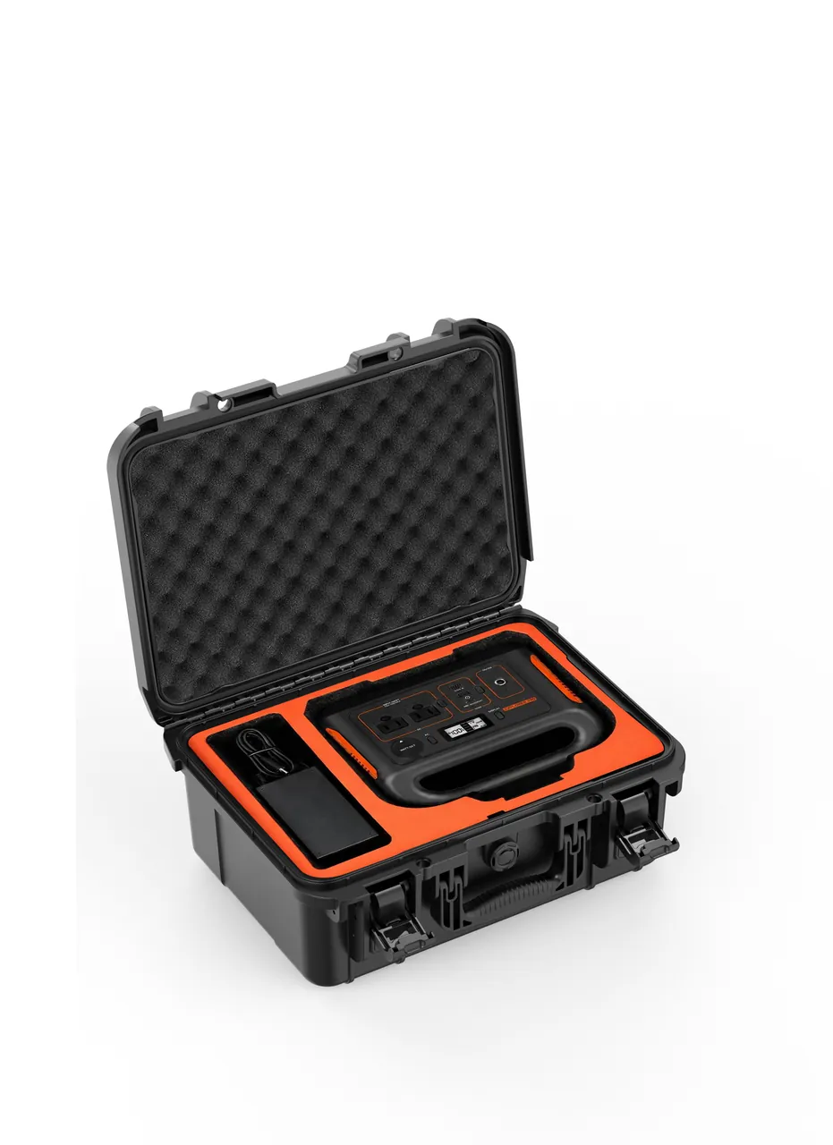
The protection logic has three layers. The first is conformity: the blade should be supported on its aerodynamic surface rather than at the tip or the platform, with the cradle routed to the airfoil profile so contact area is maximised and unit pressure minimised. The second is restraint: axial stop blocks at the root and a hold-down strip prevent the blade from sliding or rolling inside its slot. The third is isolation: each blade occupies its own slot, and adjacent blades are separated by at least ten millimetres of liner wall so they can never strike one another.
When compressor blades ship as a full set, stacking orientation also matters. Thin airfoils should stand vertically or at a steep angle so that gravity aligns with the neutral axis and long-term creep bending is minimised. If horizontal orientation is unavoidable, support points should sit at the stiffest part of the airfoil with soft limiters at both ends, and the tip must never become a bearing point.
On real projects the blade packing concept is normally fixed together with cleaning, protective oil, and desiccant decisions. If cleaning fluid or fingerprints remain on the surface, a sealed humid cavity becomes an electrochemical corrosion site, so degreasing and rust prevention must be completed before packing and the correct quantity of desiccant placed inside. Coaxial restraint practice for precision rotating and power components is discussed in Generator Set Parts Protective Cases.
Turbine Blades and Thermal Barrier Coatings: Three Red Lines
The turbine rotor blade is one of the most expensive single items in the whole machine. It is usually a directionally solidified or single-crystal casting, carrying a bond coat and a ceramic top coat that together form the thermal barrier coating, plus serpentine cooling passages and film-cooling holes inside. The coating adheres mainly through micro-mechanical interlocking and is strong in tension but weak in shear and very intolerant of repeated rubbing. That produces three red lines for transport protection.
The first red line is that coating must never touch coating. If two blades are packed bare against each other, micro-vibration during transport shears the ceramic layer at the contact point and creates spalling that is almost invisible to the eye but spreads rapidly in service. Every blade must sit in its own cavity, and cavity walls must be faced with a soft material that is halogen-free and free of plasticiser migration.
The second red line is that the tip and the cooling holes must never carry a point load. The tip is the datum for clearance control and the film holes are the outlets of the cooling design; once either is curled or blocked, blade performance degrades at once. Support must fall on the mid-span stiffened region or on the root serrations, with at least ten millimetres of free clearance left in the tip direction.
The third red line is that static charge and particulate contamination must be excluded. Conductive particles adhering to the coating produce false signals in later inspection, and hard particles entering the cavity act as abrasive media. The liner should be selected for low shedding and cleanability, and treated for antistatic performance.
| Red-line violation | Immediate consequence | In-service symptom | Preventive measure |
|---|---|---|---|
| --- | --- | --- | --- |
| Blades packed bare against each other | Shear spalling of coating | Local overheating, burn-through | Isolated cavities with soft interlayers |
| Blade tip used as a support point | Tip curl and distortion | Clearance drift, efficiency loss | Support on airfoil or root |
| Liner shedding debris | Abrasive embedded in coating | Pitting of coating | Halogen-free closed-cell material |
| No antistatic treatment | Conductive dust attraction | False inspection signals | Antistatic liner, clean handling |
| Sealed without desiccant | Electrochemical corrosion under coating | Bond coat oxidation | Humidity control and pressure valve |
Combustors and Nozzles: Thin-Wall Deformation and Contamination Control
Combustor liners are usually thin-wall welded superalloy structures with wall thickness under about 1.5 millimetres but a substantial diameter. That large-diameter, thin-wall combination is extremely sensitive to concentrated load: press a pad too firmly against the shell and roundness drifts out of tolerance; tighten a strap too hard and the weld region ripples. At the same time, the small orifices and precision fits inside fuel nozzles and swirlers are vulnerable both to mechanical damage and to carbon and foreign matter.
The underlying principle for suppressing thin-wall deformation is to convert concentrated force into distributed force. Practical measures include a collapsible internal spreader ring inside the shell, an external soft-padded band of generous width, and alignment of the internal and external constraints at the same axial position so that they clamp rather than squeeze. The spreader should have adjustable and lockable tension so it cannot loosen under vibration.
Nozzle-type precision parts need a different approach. They should be placed vertically or in their design attitude as individual items, with protective caps at the ends and orifice openings facing away from any compression direction. When several travel together, solid dividers rather than foam alone must separate them, so repeated handling cannot shift them out of position. For moisture-sensitive matched metal parts, a small desiccant pack inside the individual cavity and a humidity reading at unpacking are both worthwhile.
Contamination control matters just as much. If a liner or nozzle carries fibres, wood dust, or mould release agent into assembly, those become carbon nuclei at first ignition. The packing area should therefore operate as a clean assembly zone, with controlled floor dust, prompt removal of liner cutting debris, and a ban on friable paper or wood-wool filling. Comparable logic for thin-wall pressure-retaining and valve hardware appears in Heat Exchanger Parts Protective Cases and Pressure Vessel Component Protective Cases.

Temperature and Humidity Window for Hot-Section Transport
Hot-section materials have defined windows for both humidity and temperature cycling. Nickel superalloys are reasonably corrosion resistant on their own, but the MCrAlY-type bond coat beneath the ceramic layer oxidises selectively in humid, chloride-bearing environments, producing corrosion under the coating that visual inspection can hardly detect yet which leads to large-scale spalling in service. Titanium components are sensitive to chloride ions, and residual salt readily triggers pitting and hydrogen embrittlement.
The engineering sequence for humidity control is dehumidify, then seal, then monitor. Components and liners should be equilibrated in a dry environment before packing, the target relative humidity inside the case is generally held below forty percent, and desiccant quantity is calculated from free volume, the moisture transmission rate of the packaging materials, and the expected transit duration. Once sealed, a readable humidity indicator card should be placed in every case, and the packing date and inspection window marked on the outside.
Temperature control is really about rate rather than absolute value. In summer, a case loaded in an air-conditioned plant and then moved directly into a closed trailer can exceed fifty degrees Celsius within hours; relative humidity falls, the internal air expands, and the night-time contraction then creates a slight negative pressure that can draw moisture inward. The sensible answer is a pressure equalisation valve in the lid that lets the differential equalise slowly through a controlled path, while a hydrophobic membrane inside the valve keeps liquid water and particles out.
| Environmental risk | Trigger scenario | Effect on components | Packaging response |
|---|---|---|---|
| --- | --- | --- | --- |
| High humidity | Sea freight, rainy-season road transport | Corrosion under coating, titanium pitting | Controlled humidity, desiccant, indicator card |
| Salt spray | Coastal ports, deck stowage | Pitting, galvanic corrosion | Higher sealing rating plus salt spray testing |
| Day-night cycling | Long highway legs, air cargo holds | Condensation, repeated pressure differential | Pressure equalisation valve, absorbent liner |
| Low temperature | Winter transport at high latitude | Plastic embrittlement, hardened cushion | Low-temperature material and drop verification |
| Airborne dust | Handling at construction sites | Abrasive embedded in coating | Sealing plus clean unpacking procedure |
Cushion Liner Selection: EPE, EVA, IXPE, and Compartment Design
Choosing a cushioning material is fundamentally a stiffness matching problem. A material that is too soft creeps under long-term static load and loses restraint, while one that is too hard cannot attenuate high-frequency vibration. Gas turbine components usually need a layered combination in which each layer absorbs a different frequency band.
| Material | Density and stiffness | Rebound behaviour | Suitable components | Notes |
|---|---|---|---|---|
| --- | --- | --- | --- | --- |
| EPE pearl foam | Low density, soft | Fast rebound, low compression set | Outer cushioning for large casings | Insufficient support on its own |
| EVA foam | Medium to high, tunable | Low compression set | Blade cradles, precision locating nests | Hardness must be zoned by weight |
| IXPE cross-linked foam | Fine cell, smooth surface | Fatigue resistant, weather resistant | Contact layer for coated parts | Higher cost |
| PU pour-in-place | Moulded to contour | Highest conformity | Irregular parts, single-part cavities | Needs release treatment |
| PE sheet | Hard, dimensionally stable | Almost no rebound | Dividers, load-bearing base plates | Must be faced to avoid scuffing |
Compartmentalisation is the most underrated element of liner design. Genuine compartmentalisation is not simply cutting holes in foam; it means matching each cavity wall thickness to the weight and centre-of-height of its contents. Heavier parts get thicker walls, parts with a high centre of gravity get deeper cavities and a hold-down strip, and parts with an offset centre of gravity get a reinforced wall on the offset side. Where frequent access is required, a removable divider system can combine versatility with locating accuracy, as discussed in Removable Divider Systems and Custom Foam Inserts.
Material compatibility deserves a warning as well. Some low-cost foams release plasticiser or acidic gas inside a closed case over time, and contact with coatings or aluminium alloys produces contamination and corrosion. Material composition and volatile emission data should be requested from the supplier, and a compatibility test run where necessary, rather than comparing only price and feel.
Sealing Ratings and Pressure Equalization: Managing Pressure Differentials
Gas turbine sites are frequently located on plateaus, along coastlines, or in remote mountain areas, and a single shipment may combine a long highway leg, a marine container leg, and an inland air leg. A case therefore has to survive repeated pressure cycles from low altitude to high altitude and from high temperature to low temperature. If the case were rigidly and completely sealed, the differential would compress the gasket, make opening difficult, and draw external moisture inward as the temperature recovers.
Common industry practice satisfies two requirements at once. The case achieves IP65 to IP67 protection as defined by IEC 60529, and the lid carries a pressure equalisation valve fitted with a hydrophobic breather membrane. IP65 emphasises dust and water-jet protection while IP67 emphasises short-term immersion, and either can be acceptable for gas turbine hardware depending on whether outdoor storage and deck transport are involved. The key valve parameters are cracking pressure, airflow capacity, and membrane water resistance, all of which must be matched to case volume.
Sealing failures come down to three usual causes: foreign matter in the gasket groove, permanent set in a gasket after long compression, and insufficient latch count allowing the lid to bow. Sealing design must therefore be developed together with latch layout; when lid stiffness is marginal, the compression must be made uniform by adding latches or reinforcing the flange. Structural measures of this kind are covered in Reinforcement Rib Design and Case Seal Material Selection.
Salt Spray and Corrosion: From Inland Plants to Coastal Ports
A significant share of gas turbine projects sit at coastal power stations or on offshore platforms, so the shipping chain inevitably includes a port stage. The port environment combines high humidity, airborne chloride, and intense solar radiation, and the three together accelerate metallic corrosion markedly. This is especially dangerous for components that have been degreased and are waiting for assembly.
Corrosion protection should be split into two tracks: the component itself and the case hardware. On the component side the priorities are pre-treatment, meaning cleaning, degreasing, and either rust-preventive oil or vapour-phase protection, plus maintaining low internal humidity. On the hardware side the priorities are the material of latches, hinges, and the pressure valve, favouring stainless steel or surface-treated metal and avoiding direct contact between dissimilar metals that would form a galvanic couple.
For verification, a neutral salt spray test can be run to GB/T 10125 with duration and evaluation method agreed between parties, or to ASTM B117 when a customer standard governs. It is worth stating that test duration and acceptance level should be tied to the actual service environment rather than simply maximised; an excessively long test cycle raises cost without addressing real risk. Weather resistance in general is discussed in Salt Spray Corrosion Testing for Cases and Rain and Humidity Design for Outdoor Cases.
Vibration and Shock: Transport Test Standards and Acceptance Criteria
The hardest transport load to quantify is resonance. Once the natural frequency of the truck suspension, the container stacking pattern, and the three-stage case-liner-component system coincide at a particular road speed, the acceleration experienced by the component can reach three to five times the level measured on a smooth road. The goal of protection design is not to drive acceleration to zero, which is impossible, but to keep system natural frequencies away from common excitation bands and to hold transmissibility low in the critical range.
| Test item | Common standard | Key parameters | Recommended criterion |
|---|---|---|---|
| --- | --- | --- | --- |
| Fixed-frequency vibration | GB/T 4857 series | Acceleration, frequency, duration | No displacement, no scuffing |
| Random vibration | ASTM D4169 cycle | PSD profile, duration | No loosening, no cracking |
| Drop test | ISTA 1A or 2A | Drop height, attitude | No functional damage to component |
| Stacking load | ISTA or company standard | Load, duration, temperature and humidity | No collapse, no permanent deformation |
| Incline impact | GB/T 4857 | Impact velocity | Latches remain engaged |
Acceptance criteria are best written in layers. The outer case may be allowed light scuffing and the liner limited compression, but the component itself must satisfy three conditions: no displacement, no scuffing, and no functional damage. Beyond visual inspection, high-precision items should have critical dimensions re-measured, such as the tip clearance datum, roundness, or flange flatness. Test methods and common misunderstandings are treated in Vibration and Resonance in Transport and ISTA Transport Testing Procedures.
Stacking Load, Lifting, and Pallet Planning
Large casings and combustors are bulky with concentrated mass, so the case base and liner base plate carry long-term static load rather than instantaneous shock. Design must distinguish short-term stacking during transport from stacking over months of storage; the former can be assessed against transit duration, while the latter must account for slow compression caused by creep.
A stacking calculation should cover at least four items: gross weight per case, number of stacked layers, permissible static load on the bottom case, and a temperature correction factor for the storage environment. High storage temperature reduces the stiffness of a plastic case, and the permissible static load must be reduced accordingly. Stacking attitude should also be fixed, with a batch stacked in one consistent orientation so that cross-stacking does not create local load concentrations.
Lifting often carries more risk than stacking. Large casings should be handled with dedicated gear such as padded slings or a custom lifting beam, never with wire rope bearing directly on the case. Lifting points should be defined at the design stage, marked on the case, and supplemented by stencilled centre-of-gravity and lifting diagrams on the outer surface. Pallets should present a flat top face with no protruding nail heads, with anti-slip pads between case and pallet and strapping applied on the principle that the lid carries no load. A fuller method for stacking and pallet planning is given in Case Stackability and Pallet Planning.
Custom Liner Processes: CNC Routing, Thermoforming, and Surface Facing
The liner process determines whether a concept can be reproduced reliably. Three routes dominate today. The first is CNC routing, in which toolpaths are programmed from component 3D data and cavities are cut directly from EVA or EPE board; this suits small batches, irregular surfaces, and deep cavities with good dimensional consistency, but material utilisation is relatively low. The second is thermoforming, in which sheet is heated and vacuum-drawn over a mould; this suits medium to large batches and moderately regular surfaces at low unit cost, but requires tooling. The third is pour-in-place foaming directly around the packed item, which gives the highest conformity for single or highly irregular parts but demands careful operation and release control.
Selecting a route depends on batch size and precision demands. If blade shipments reach thousands of pieces a year with a stable profile, thermoforming combined with a compartment frame is usually the most economical answer. If only a few dozen pieces ship annually across frequently changing models, CNC routing is more flexible. Whichever route is chosen, a first-article confirmation is mandatory, trial-fitting the actual component or an equivalent gauge to check conformity, insertion force, restraint reliability, and free tip clearance.
Surface facing is often overlooked yet strongly affects coated parts. The contact layer should be a fine, closed-cell, non-shedding material bonded as a single sheet so that no joint seam can introduce dust. Adhesive should be a low-volatile formulation fully cured and odour-equilibrated before packing, so that residual volatiles do not accumulate in a closed case. Trade-offs between liner processes and cost are detailed in EVA Thermoformed Liner Process and Case Foam Material Comparison.
Acceptance Criteria and Documentation
When a custom case is delivered, it should be accepted item by item across four categories, case body, liner, accessories, and documents, rather than judged on appearance alone. Case body inspection covers gasket surfaces, latch operation, hinge play, and valve airflow. Liner inspection covers cavity dimensions, hardness zoning, and freedom from shedding in the contact layer. Accessory inspection covers lifting gear, dividers, record cards, and desiccant quantity. Document inspection covers drawing consistency, material data, test reports, and the packing list. For volume deliveries, a sampling level and decision rule can be set, following the approach in Custom Case Acceptance and AQL.
Documentation matters more for gas turbine projects than for most cargo. Alongside the packing list, the case should carry a declaration of liner material and composition including halogen and volatile statements, desiccant type and dosage, a record of packing-environment humidity, a summary of transport test reports, and unpacking and repacking instructions. For overhaul parts that travel round trips, a reusable loading diagram should be supplied, numbering every cavity so that the return leg reproduces the same locating arrangement. General expectations for documentation and traceability appear in Case Asset QR Code Tracking and Export Packaging Compliance for Cases.
Frequently Asked Questions FAQ
Q: Can compressor blades and turbine blades be shipped together in a single protective case?
A: As a rule this is not recommended, and if it is unavoidable the case must be strictly partitioned. The two families fail differently: compressor blades suffer bending and tip curling, solved by contoured support and axial restraint, while turbine blades suffer shear spalling of the coating, solved by isolated soft cavities and friction-free support. Their mass, centre of gravity, and bearing surfaces also differ, so sharing a cavity forces the restraints to compromise. Where a project genuinely requires combined shipment, the case should be divided along its axis into two physically separate chambers, each with its own liner and hold-down strips, separated by a rigid bulkhead, and each cavity numbered on the lid. Handling should avoid one-sided loading, and lifting the whole case by pulling on one liner must never be permitted. Within each chamber, cavity depth should be set so the blade rests on its root serrations or its mid-span rather than on the leading edge, and a numbered position map should travel with the case so that the same arrangement is reproduced on every later trip.
Q: What damages a thermal barrier coated blade most during transport?
A: Three actions dominate: shear friction, point loading, and moisture. The coating bonds to the substrate mainly through mechanical interlocking, so it tolerates tension reasonably but tolerates shear poorly, and slight relative sliding between two blades can spall the ceramic layer at the contact point. If the tip or a cooling hole carries a concentrated force, it curls or deforms, destroying clearance control and film cooling immediately. The bond coat also oxidises selectively in humid, chloride-bearing air, producing corrosion beneath the coating that visual inspection cannot reveal yet which may detach in large flakes in service. Protection therefore requires isolated cavities, soft friction-free support, free tip clearance, humidity control, and desiccant. Degreasing and rust prevention should be completed before packing, and the contact layer should be a closed-cell non-shedding material. Blades should also be packed with the tip facing free space rather than a cavity wall, and cavity depth should exceed blade length by enough that no axial force ever reaches the tip when the lid is compressed during stacking.
Q: Why do thin-wall parts such as combustor liners deform so easily, and how does a case suppress it?
A: The core reason is small wall thickness, large diameter, and low local stiffness, which makes the structure very sensitive to concentrated load. A pad pressed too hard, a strap tensioned too deeply, or a localised support point during stacking can all push roundness and flatness out of tolerance, and the problem usually appears only at assembly. The suppression principle is to convert concentrated force into distributed force: fit a collapsible and lockable internal spreader ring inside the shell, apply a generously wide soft-padded band externally, align the internal and external constraints at the same axial position so they clamp rather than squeeze, support the base over its full face rather than at points, and limit stacking height with a load-bearing base plate. First-article confirmation should measure roundness and flange flatness as the delivery baseline, and it should repeat that measurement after a simulated stacking load rather than only immediately after unpacking. A liner that supports the shell along its full length is preferable to one that grips near the weld seams, because the seams behave as stress risers.
Q: Why is moisture control mandatory for gas turbine components, and how is desiccant sized?
A: Because humidity causes hidden and irreversible damage. The bond coat on nickel alloys is prone to oxidation beneath the coating in humid chloride-bearing environments, titanium components are sensitive to chloride ions, and residual salt can trigger pitting and hydrogen embrittlement; these defects are usually invisible externally yet grow in service. The engineering sequence is dehumidify, then seal, then monitor. Components and liners are equilibrated in a dry environment before packing, and internal relative humidity is generally held below forty percent. Desiccant quantity is calculated from the free volume of the case, the moisture transmission rate of the materials, and the transit duration, rather than estimated by habit. After sealing, a readable humidity indicator card goes into every case, and the packing date and inspection window are marked outside. Readings should be recorded at unpacking and filed as evidence in the transport chain. Where a project specifies a maximum internal humidity at unpacking, that figure belongs in the technical agreement alongside the desiccant specification and the indicator card type, so the requirement can be verified instead of assumed.
Q: How do sea freight and air freight differ in what they demand from a protective case?
A: The differences concentrate on pressure differential, humidity, and stacking. In an air cargo hold, pressure changes quickly and the differential across the case reverses repeatedly; without a suitable pressure equalisation valve, the gasket is compressed and moisture is drawn in. Sea freight involves a long transit, high humidity, and possible deck-level heat, so it demands a higher sealing rating, a larger desiccant dose, and salt-spray-resistant hardware. On stacking, container stowage is usually taller and longer, placing a greater long-term static load on the case base and floor plate, which must be assessed against months of storage and creep. Sea freight is also handled repeatedly at ports with more impact events, so liner restraint must return to position reliably after repeated loading and unloading. Air legs invert that balance, with more individual handlings but far shorter exposure, which is why desiccant dosing has to be tied to transit duration rather than to a fixed rule of thumb. In both modes, the case should be opened only in a dry, clean area to avoid undoing the protection achieved in transit.
Q: How can the shock attenuation of a gas turbine component case be verified as adequate?
A: Verification must come from testing rather than from handling impressions. A basic combination covers fixed-frequency and random vibration, drop, stacking load, and incline impact, referencing the GB/T 4857 series and the ASTM D4169 cycle, with drop height and attitude chosen per ISTA 1A or 2A. During testing, accelerometers should be placed at critical positions inside the case to measure transmissibility from the case base to the component support surface, confirming that system natural frequencies avoid common transport excitation bands. Judgement uses layered criteria: the outer case may be allowed light scuffing and the liner limited compression, while the component itself must show no displacement, no scuffing, and no functional damage. High-precision items should additionally have the tip clearance datum, roundness, or flatness re-measured. Test results should be archived with the case and referenced in the technical agreement, so that a later dispute about packaging adequacy can be settled against measured data instead of recollection. Where in-house equipment is unavailable, an accredited laboratory report is the practical alternative.
Q: How should liner materials and compartment structure be selected?
A: First determine the contact layer from the failure mechanism of the component, then determine the load-bearing layer from its mass and centre of gravity. For coated parts the contact layer should be fine-celled, closed, non-shedding, and low-volatile, avoiding low-cost foams that may release plasticiser or acidic gas. The load-bearing layer is chosen from EVA or PE board according to mass, with heavier parts using higher density and thicker cavity walls. Compartmentalisation is not simply cutting holes; cavity wall thickness should match the mass of its contents and cavity depth should match centre-of-gravity height, with offset parts reinforced on the offset side. When several families share a case, rigid dividers should break the different load paths so that heavy parts cannot press continuously on light ones through the liner. Every concept should pass a first-article trial fitting that confirms insertion force and restraint reliability. Where several components share one case, the heaviest item should be placed over the stiffest part of the base plate, and the loading diagram should show that arrangement so that it survives staff changes and repeated use.
Q: What do delivery lead time, accompanying documentation, and acceptance criteria typically cover?
A: Acceptance is best performed item by item across case body, liner, accessories, and documents. The case body check covers gasket surfaces, latches, hinges, and pressure equalisation valve condition. The liner check covers cavity dimensions, hardness zoning, and whether the contact layer sheds. Accessories are verified for lifting gear, dividers, record cards, and desiccant quantity and specification. Documents are checked for drawing consistency, material composition and volatile declarations, packing humidity records, transport test report summaries, and unpacking and repacking instructions. Volume deliveries can define a sampling level and decision rule. Gas turbine projects normally also require a reusable loading diagram with numbered cavity positions, ensuring the same locating arrangement on the return leg so that overhaul parts can be repacked quickly.
Conclusion and Related Reading
Gas turbine transport protection means locking spatial position, managing humidity and pressure differential, and designing the shock load path. JUNZHIJIA supplies custom compartmentalised cases with sealed moisture control and pressure equalisation, plus OEM/ODM support.
Related Reading