

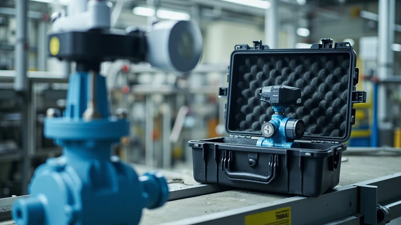
Petrochemical valves and actuators are the most numerous and most frequently replaced rotating-equipment accessories in any process plant. They share three traits: many sealing interfaces, many attached accessories, and high sensitivity to cleanliness. The conclusion up front: a petrochemical valve and actuator case must solve three problems at once. Flange sealing faces and seat sealing faces must never be chipped or scored. Valve stems and actuator drive components must never be bent by lateral force. Electric and pneumatic accessories must be protected from moisture, dust and static discharge. The case shell should therefore be IP65 or better, with IP67 for ocean freight or open-yard storage. Inserts should follow a one-valve-per-compartment layout with suspended flange faces and a separate accessory bay, and the terminal compartment and breather ports of electric actuators need dedicated plugs.
Field experience repeats itself. A DN200 gate valve arrives with a light score across the flange serrations. It looks minor, but the joint weeps during pressure testing and the whole valve goes back. An electric actuator takes on moisture during the rainy season, condensation forms in the terminal compartment, and the unit has to be opened, dried and re-tested for insulation resistance before installation. A pneumatic ball valve's positioner tubing fitting is crushed inside the case, and commissioning stalls while technicians chase the fault. The root cause in each case is not rough handling by the freight carrier. It is a packaging concept that ignores the actual weak points of valves and actuators. This article works through the valve body, sealing faces, stem, actuator and accessories layer by layer, and gives directly usable case selection, insert design, port capping and acceptance guidance for equipment and procurement teams in petrochemical, refining, coal chemical and pipeline storage operations.
Table of Contents
- 1. Protection Challenges for Petrochemical Valves and Actuators
- 2. Weak Points in Valve Bodies and Sealing Faces
- 3. Actuators: Pneumatic, Electric and Hydraulic Differences
- 4. Case Selection: Cleanliness, Moisture, Load and Protection Rating
- 5. Insert Design: One Valve per Compartment and Suspended Flange Faces
- 6. Face Caps, Stem Limits and the Separate Accessory Bay
- 7. Moisture, Rust and Cleanliness Control
- 8. Vibration, Shock and Transport Test Verification
- 9. Corrosion and Salt Spray Response
- 10. Hazardous Area Awareness and Marking Boundaries
- 11. Incoming Inspection, AQL Sampling and Traceability Labels
- 12. Custom Insert Workflow and OEM/ODM Delivery
- 13. Selection Decision Tables and Common Misconceptions
- Frequently Asked Questions
- Conclusion & Related Reading
1. Protection Challenges for Petrochemical Valves and Actuators
Process plants use valves in the thousands, and every turnaround brings a wave of valve replacement and repair transport. Compared with general machinery spares, valves and actuators present three distinctive packaging challenges.
- Many sealing interfaces, all of them hard fits. A ball valve alone includes the seat-to-ball contact, the stem-to-packing interface, both flange sealing faces and the body joint seal. These are usually metal-to-metal hard seals or rely on very thin soft sealing elements to achieve zero leakage. Any impact, dent or score is a fatal defect.
- Structurally top-heavy. The body is heavy, but the stem, yoke, cylinder or motor sits on top, raising the center of gravity and creating a cantilever. Lateral vibration in transit generates bending moment at the stem or yoke root, causing slight stem bending that changes operating torque, or in worse cases cracking the cast yoke.
- Many fragile accessories. Positioners, solenoids, limit switches, filter regulators, handwheels and cable glands are often easier to damage than the valve itself. Most are plastic housings, thin-wall metal parts or precision electronics, sensitive to crushing, dust and moisture.
Valve case design therefore differs fundamentally from general tool spare cases. The goal is not to fit the valve in, but to keep every sealing face suspended or softly contacted, keep the stem and yoke free of lateral bending moment, and give accessories an independent, moisture-protected home. The sensitivity-zoning principle described in the custom foam insert design guide is at its most relevant with valve-class components.
One additional consideration: petrochemical valves normally go through pressure testing, dye penetrant checks and dimensional re-verification after arrival. The ease of unloading directly affects the efficiency of those steps. If the insert is too tight, has no handle cutouts and carries no location markings, unpacking turns destructive, consuming time and risking damage.
2. Weak Points in Valve Bodies and Sealing Faces
Valve types differ widely, and so do their weak points. The table below summarizes protection priorities by type.
| Valve type | Critical sealing / mating face | Typical transport failure | Insert and protection notes |
|---|---|---|---|
| --- | --- | --- | --- |
| Gate and globe valves | Flange serrations, seat-to-disc mating face | Serration scoring, disc skewing, packing gland loosening | Stand upright, fit flange face caps, fix disc in half-open or closed position |
| Ball valves | Ball sphere, soft seat rings, stem packing area | Sphere scoring, soft seat deformation, stem bending | Never load the ball, leave the seat area clear, guide the stem |
| Butterfly valves | Seat elastomer, disc sealing edge | Permanent seat compression set, disc edge rolling | Keep disc slightly open, no static load on the elastomer |
| Check valves | Disc-to-seat guiding surfaces | Disc sticking, spring displacement | Retain factory attitude, never stack inverted |
| Safety relief valves | Disc-to-nozzle sealing face, spring | Sealing face denting, spring preload change, set pressure drift | No impacts, no heat exposure, one valve per compartment |
| Control valves | Trim-to-seat throttling surface, guide bushing, packing | Trim scoring, guide galling, travel mark shift | Keep factory travel lock, no load on the trim |
| Diaphragm valves | Diaphragm, lining | Diaphragm deformation, lining cracking | Avoid compression, keep away from light and heat |
| Knife gate valves | Knife edge, seal seat | Edge rolling, seat ring deformation | Fix knife fully open or closed, keep the edge clear |
On materials, three details deserve attention.
- Cast bodies have limited impact tolerance. Grey cast iron and some ductile irons can develop microcracks under point impact, particularly at the neck and flange root. The case must not let the body take point loads.
- Soft sealing materials dislike oil, heat and compression. PTFE, PFA, EPDM and FKM take a permanent set under long-term compression. Packaging must not leave sealing elements squeezed.
- Stainless bodies and carbon steel yokes need isolation. Dissimilar metals in long contact under damp conditions cause galvanic corrosion. Insert an insulating separator between them.
The critical rule: no valve should ever bear load on its flange sealing faces, or touch the case wall or another valve body. The correct approach is to support the valve on rigid cast features such as the body side wall or base, leave the flange faces suspended, and fit face caps made of plastic or wood with a soft backing. For large-diameter valves, add a dedicated cradle so the valve stands or lies without cantilever.
3. Actuators: Pneumatic, Electric and Hydraulic Differences
Actuators are the least robust part of a valve case and need separate design by drive type.
| Drive type | Main parts | Main risks | Protection notes |
|---|---|---|---|
| --- | --- | --- | --- |
| Pneumatic (cylinder or diaphragm) | Cylinder, piston, spring, air ports | Cylinder deformation, dust ingress to spring chamber, broken fittings | Dust plugs on breathers, caps on air ports, no compression loads |
| Electric | Motor, gearbox, torque switch, terminal compartment, handwheel | Condensation in terminal compartment, insulation loss, handwheel impact, window breakage | Plug terminal compartment, add desiccant, separate compartment, moisture bag |
| Hydraulic / electro-hydraulic | Cylinder, accumulator, hydraulic lines, control block | Oil leakage, deformed fittings, broken gauges | Drain and plug oil ports, pack gauges separately |
| Gas-over-oil | Combination of the above | Combined risks, uneven weight distribution | Multi-point support by center of gravity, dedicated accessory bay |
For electric actuators specifically, add these actions to the packaging process.
- Plug the terminal compartment and breathers. Seal cable entries with dedicated plugs or blind plates, and fit desiccant breathers or temporary plugs to breather ports to keep moisture and dust out.
- Combine insulation and moisture control. Place desiccant and a humidity indicator card in the accessory bay, targeting below 50 percent relative humidity inside the case. For long ocean shipments, consider bagging the whole unit in PE with vacuum or nitrogen per the manufacturer's recommendation.
- Protect the handwheel and operating gear. Fit an annular foam guard around the handwheel rim so it cannot strike the case wall. Keep the handwheel installed but locked against rotation so free spinning cannot shock internal mechanical limits.
- Protect display windows and nameplates. Apply peelable protective film to avoid scratching or hazing that would impair field readings.
- Manage static. Where the actuator contains circuit boards and sensors, use static-dissipative insert material or add a conductive liner in the accessory bay. Zoning practice is covered in ESD shielding case design.
Pneumatic actuators are more robust, but two details are routinely missed. First, breather dust protection. If the breather is open during transport, fine dust enters the spring chamber and can later cause piston sticking. Second, spring chamber safety labeling. Diaphragm actuators contain preloaded springs, so the case and documentation should state clearly that untrained personnel must not dismantle the unit.
4. Case Selection: Cleanliness, Moisture, Load and Protection Rating
The shell is the base layer of the protection system. Selection should lock down four parameter groups: protection rating, material, internal dimensions with load capacity, and hardware configuration.
Ingress protection follows IEC 60529 and its Chinese equivalent GB/T 4208. For petrochemical valve and actuator cases, use the table below.
| Rating | Dust | Water | Typical scenario | Recommendation |
|---|---|---|---|---|
| --- | --- | --- | --- | --- |
| IP54 | Limited dust protection | Splash resistant | Covered in-plant transfer, short storage | Not recommended for inter-regional freight |
| IP65 | Dust tight | Water jet resistant | Normal road and rail freight, indoor warehouse | Minimum bar for petrochemical valve cases |
| IP67 | Dust tight | Temporary immersion (1 m / 30 min) | Ocean export, open yards, wet regions | Strongly recommended for electric actuators |
| IP68 | Dust tight | Continuous immersion by agreement | Special conditions | Usually over-engineered here |
On material, three mainstream routes each involve trade-offs.
- One-piece injection molded PP or PE cases. Excellent sealing, good chemical resistance, low weight. Suited to small and medium valves, actuators and accessory cases. Higher tooling cost and limited maximum length and width.
- Copolymer polypropylene panel cases with aluminum frames. Flexible dimensions and high strength, capable of DN300 and above valves and long valve assemblies, sealed by gaskets compressed by latches.
- Rotomolded LLDPE cases. Best impact resistance, large formats with an internal metal frame, suited to heavy valves and lifting applications. The trade-off is weight and volume cost.
For more on how protection ratings map to international standards, see IP67 protective case sealing structure and verification.
On hardware, hinges, latches and gaskets are the weak link in case life. Petrochemical sites commonly report the case surviving while the latch fails first, destroying the seal. For hinge styles, latch fatigue and replaceable gasket design, see toolbox hinge, latch and seal selection. Where inventory control matters, numbered locks or seal structures can be specified, as covered in case lock customization options.
JUNZHJIA, manufactured by Kexin New Materials (Guangdong) Co., Ltd., commonly builds petrochemical valve cases as PP panel with aluminum frame and replaceable gaskets, with internal height customized to valve bore and actuator height, and supplies protection rating statements and material certificates for incoming document checks.

5. Insert Design: One Valve per Compartment and Suspended Flange Faces
Insert design has to deliver mechanical restraint and surface protection at the same time. Petrochemical valve case inserts normally follow six steps.
- Build the valve list. Record model, bore, pressure class, face-to-face length, overall height including actuator, unit weight and the location of every sealing face.
- Fix the shipping attitude. Gate, globe and check valves should stand upright or on their side so the stem is not under sustained bending moment. Ball and butterfly valves keep their factory position. Valves with actuators should have the actuator up or to the side, never inverted and load-bearing.
- Divide compartments and layers. One valve per compartment, heavy valves on the lower layer, actuators and accessories above or in a separate bay. Never let a valve body rest on an actuator.
- Design suspension and support features. Flange faces, seat areas and stem packing areas stay clear. Support points go on rigid cast features with EVA or PU profile cradles.
- Add limit and fixing features. Steps, bosses, clamp bars and straps restrain the body in all three axes so nothing shifts when the case is inverted or vibrated.
- Leave ergonomic and inspection space. Large valves need handle cutouts and tilt ramps. Valves awaiting pressure test should come out without destroying the insert.
Insert material combinations:
| Material | Density range | Characteristics | Typical application |
|---|---|---|---|
| --- | --- | --- | --- |
| EVA foam | 60 to 120 kg/m3 | Tunable stiffness, CNC carveable, low shedding | Body location, suspended flange support |
| PU foam | 30 to 80 kg/m3 | Molded in one piece, good energy absorption | Irregular body wrapping, accessory bay |
| PE foam | 25 to 45 kg/m3 | Low cost, easy to cut | Large-part bedding, filling |
| XPE crosslinked foam | 30 to 60 kg/m3 | Thermoformable, thin-wall friendly | Panels, instrument bays |
| Felt / nonwoven | Not applicable | Anti-scratch, lint-free | Precision contact layer |
| Rigid divider (PP, PVC, plywood) | Not applicable | Load bearing, isolating | Layer separation, heavy valve support |
For differences in compression set, temperature-humidity cycling and durability across foam types, see case foam material comparison. Where valve models change frequently in a spare parts store, a removable divider system allows rapid reconfiguration instead of re-making the insert every time a size changes.
6. Face Caps, Stem Limits and the Separate Accessory Bay
This section covers the three actions that distinguish a valve case from other industrial cases.
Flange face caps
Regardless of whether a flange uses a raised face, a tongue-and-groove face or a ring joint face, the sealing surface must not be touched. Practical measures:
- Fit a plastic or wooden circular cap with a soft backing, snapped or strapped onto the flange so no metal is exposed.
- For ring joint (RTJ) groove faces, the cap needs an annular boss that seats into the groove to keep debris out of the groove bottom.
- Mark the cap with bore, pressure class and a note that bare shipping after removal is prohibited.
- Cap materials must be free of sulfur and free of chlorine to avoid stress corrosion risk.
Stem and yoke limits
The stem is the most unfavorable location for bending moment. Limit measures include:
- Add profile support blocks on two or four sides of the stem so the stem is not the sole load path.
- Fit anti-rotation clamps on handwheels or gearbox input shafts so free spinning in transit cannot damage limit switches or travel mechanisms.
- Add an annular guard at the yoke root so it does not become a stress concentration.
- Never use the stem as a lifting point. The case must clearly mark the lifting locations.
Separate accessory bay
Positioners, solenoids, limit switches, filter regulators and junction boxes must be stored separately from the valve body or in a divided bay. The reason is simple: these accessory housings are mostly engineering plastic or thin-wall cast aluminum and cannot carry the weight of a valve body. Recommendations:
- Provide a dedicated accessory bay at the top or side of the case with its own insert.
- When customers remove accessories and ship them with the valve, compartment them one by one from the accessory list and keep mounting bolts and gaskets in dedicated bags.
- Coil and secure tubing, cables and fittings separately to avoid sharp bends, and cap tube ends.
- Place desiccant and a humidity indicator card in the accessory bay, sharing the case but maintaining a sealed zone.
7. Moisture, Rust and Cleanliness Control
Petrochemical valves often sit in the warehouse for some time after arrival, and humidity control determines whether extra derusting and cleaning are needed later.
Moisture control
- Desiccant sizing. Calculate from internal free volume and transit duration. A practical rule is 1 to 2 kg of high-performance desiccant per cubic meter of free volume, doubled for long ocean voyages.
- Humidity indicator cards. Place where they can be read immediately on opening, and treat them as acceptance evidence. Target below 60 percent relative humidity at opening, and below 50 percent for electric actuator cases.
- Vapor corrosion inhibitor. Use VCI film, VCI paper or emitters for carbon steel bodies, bolts and yokes. Confirm compatibility with copper, zinc and magnesium individually.
- Pressure equalization valves. A well-sealed case develops a pressure differential across climate zones or in air freight, making the case hard to open or damaging the gasket. See case pressure equalization valve configuration.
Cleanliness control
Valve cleanliness directly affects the risk of internal leakage after commissioning. ISO 4406 expresses solid particle contamination level using three code numbers for particles above 4, 6 and 14 micrometers. Although aimed at operating fluids, its particle control logic applies directly to packaging.
- Cap all body cavities, flange ports and oil ports with plugs or heat-shrink caps to keep dust and debris out.
- Choose closed-cell, low-shedding insert material and avoid aged, crumbling foam.
- Clean cavities with lint-free cloth and isopropyl alcohol, then let them dry naturally before loading valves.
- Double-pack precision internals such as control valve trim and relief valve discs in PE bags.
- Unpack in a clean area rather than opening packaging on the process unit.
For cleaning and routine maintenance practice, see how to clean a protective case.
8. Vibration, Shock and Transport Test Verification
Valve and actuator cases face complex transport conditions and must handle both long-duration vibration, which is a fatigue issue, and handling impacts, which are a strength issue.
Three international test families are commonly used.
- ISTA. The ISTA 1 series is a non-simulation integrity test suitable for factory screening. The ISTA 3 series, general simulation performance tests, adds conditioning, random vibration, drops and shock and tracks real distribution environments more closely. Export shipments to Europe and North America often specify ISTA 3A, covered further in ISTA transport testing procedure.
- ASTM D4169. Framed around a distribution cycle, with sequences and assurance levels selected by transport mode. Suited to long-haul air plus road combinations. See ASTM D4169 distribution cycle testing.
- GB/T 4857. The Chinese family of basic transport package test methods covering stacking, vibration, impact and drop, and the most cited basis in domestic tenders. See GB/T 4857 transport packaging testing.
Environmental conditions can be cited from MIL-STD-810H method numbers and levels for vibration, shock and humidity. It must be stated clearly: citing MIL-STD-810H methods only standardizes test conditions. It does not mean the product holds any military certification, nor that it passed every test in the standard. Compliance wording is discussed in MIL-STD-810H case compliance.
Recommended verification package for valve cases:
| Test | Reference basis | Key observation | Pass criterion (rule of thumb) |
|---|---|---|---|
| --- | --- | --- | --- |
| Random vibration | ISTA 3 / GB/T 4857.23 | Insert displacement, body-to-wall contact | No displacement, no contact marks |
| Drop | ISTA 3A / GB/T 4857.5 | Corner, edge and face each once | Case not ruptured, insert set under 10 percent |
| Stacking compression | GB/T 4857.3 and .4 | Case collapse, insert resilience | Dimensional change within allowance |
| Temperature-humidity conditioning | GB/T 4857.2 | Condensation, rust, label lift | No condensation, no rust spots |
| Post-test inspection | Company procedure | Flange faces, stem runout, accessory appearance | No scoring, runout within tolerance |
Practical note: for valves with electric actuators, add an insulation resistance re-test as a mandatory opening check. Moisture-induced insulation loss is the most common arrival defect.
9. Corrosion and Salt Spray Response
High salt spray environments at coastal refineries, river terminals and offshore platforms test both case and valve. Treat case corrosion and component corrosion as separate problems.
- Case and hardware. Prefer stainless steel for hinges, latches and corner wraps. If carbon steel is used, specify the plating and coating system. Evaluate with neutral salt spray per ISO 9227, the standard for corrosion tests in artificial atmospheres, salt spray tests. For coastal and offshore use, a practical requirement is 96 to 480 hours with no red rust, per contract.
- Component-level material awareness. The petrochemical industry applies requirements for resistance to environmental and sulfide stress cracking, commonly cited through NACE MR0175 / ISO 15156. A packaging case itself is not subject to NACE material certification, but packaging materials must be free of sulfur and chlorine and must not use recycled content or adhesives that could release corrosive species.
- Isolation. Stainless valves need separate compartments or insulating separators from carbon steel yokes and bolts. Wooden supports require attention to moisture content and export fumigation requirements (ISPM 15) to avoid wood-borne moisture and leachates.
- Coating protection. Exterior coatings abrade easily in transit. Use felt or lint-free cloth at contact points, and avoid solvent-based cleaners that react with the coating.
Procurement tip: state in the technical requirement that packaging materials must be free of sulfur, free of chlorine and free of recycled content. This measurably reduces corrosion-related complaints.
10. Hazardous Area Awareness and Marking Boundaries
Process plants contain explosive gas atmospheres. IEC 60079, the international family for equipment in explosive atmospheres, with its Chinese counterpart GB 3836, is the governing framework. The core point:
A protective case is an outer packaging container, not explosion-proof electrical equipment. Packing valves and actuators in an IP67 case grants no explosion protection certification, and the fact that valves serve a hazardous area does not imply the packaging needs such certification. The case's role is to have contents unpacked and handed over at the periphery of the process area, in a warehouse or in a maintenance shop. The case itself does not operate while energized.
Even so, packaging design should observe the following.
- Avoid large-area direct contact between static-accumulating plastic inserts and metal valve bodies, adding conductive layers or grounding where needed.
- Mark cases and labels with wording such as not an explosion-proof container, do not open inside a hazardous area, with exact wording per plant HSE rules.
- When handling inside a classified area, follow site hot work and static control rules, and never drag metal case parts across the ground.
- For used valves containing residual oil or liquid, drain and clean to hazardous goods requirements before packing, applying ADR and IMDG hazmat transport packaging rules where relevant.
- For parts with preloaded springs such as relief valves, mark the case clearly with do not dismantle, do not impact.
Defining the boundary and marking it professionally reduces back-and-forth between procurement, HSE and operations.
11. Incoming Inspection, AQL Sampling and Traceability Labels
Packaging value is proven at acceptance. Three items belong in the contract.
- Arrival condition check. Case intact, no water ingress traces, gaskets complete, humidity card in range, seal numbers continuous.
- Sampling inspection on opening. Determine the plan per GB/T 2828.1, the standard for sampling procedures for inspection by attributes, with an agreed AQL. See custom case acceptance and AQL for worked examples.
- Component condition verification. Check flange faces, seats, stems, accessories and coatings item by item against factory records.
Suggested inspection checklist:
| Check item | Method | Acceptance basis | Action on failure |
|---|---|---|---|
| --- | --- | --- | --- |
| Case appearance and sealing | Visual plus seal number check | No damage, no water ingress | Isolate and inspect contents fully |
| Internal humidity | Humidity indicator card | RH at or below 60 percent (50 percent for actuators) | Replace desiccant and recheck |
| Insert integrity | Visual and tactile | No powdering, collapse or displacement | Replace insert |
| Flange sealing faces | Visual serration comparison, dye check if needed | No serration scoring, no dents | Return and trigger analysis |
| Seat and ball or disc | Visual plus manual operation | No scoring, no sticking | Return or repair |
| Stem runout | Dial indicator | Within design tolerance | Return for straightening or claim |
| Actuator insulation | Megohmmeter | Meets manufacturer value | Dry and re-test, or reject |
| Accessories and labels | Visual plus list cross-check | Consistent and traceable | Reissue documents or accessories |
Labels deliver high return at low cost. Use weather-resistant plates on every case showing valve name and model, bore and pressure class, plant and line number, quantity, manufacturing date, packing date, case number and a QR code linking to the electronic record. For a petrochemical operator, the value of spares that can be found, matched and traced pays back within a single turnaround.
12. Custom Insert Workflow and OEM/ODM Delivery
For petrochemical users with recurring, volume supply, packaging belongs inside supplier system management rather than ad hoc purchasing. JUNZHJIA, manufactured by Kexin New Materials (Guangdong) Co., Ltd., serves global wholesale, distribution and OEM/ODM customers with one-stop support from case selection and insert customization to documentation. A typical workflow:
- Requirements gathering. Customer provides valve and actuator drawings or samples, packing list, transport modes (sea, air, road), destination regulatory requirements, annual volume and batch cadence.
- Concept design. Case specification, material, protection rating, hardware configuration, insert layer drawings and 3D assembly views.
- Prototype confirmation. First case and insert built so the customer can load actual valves and verify handling and restraint.
- Test verification. Vibration, drop, stacking and temperature-humidity cycling as agreed, with test records issued.
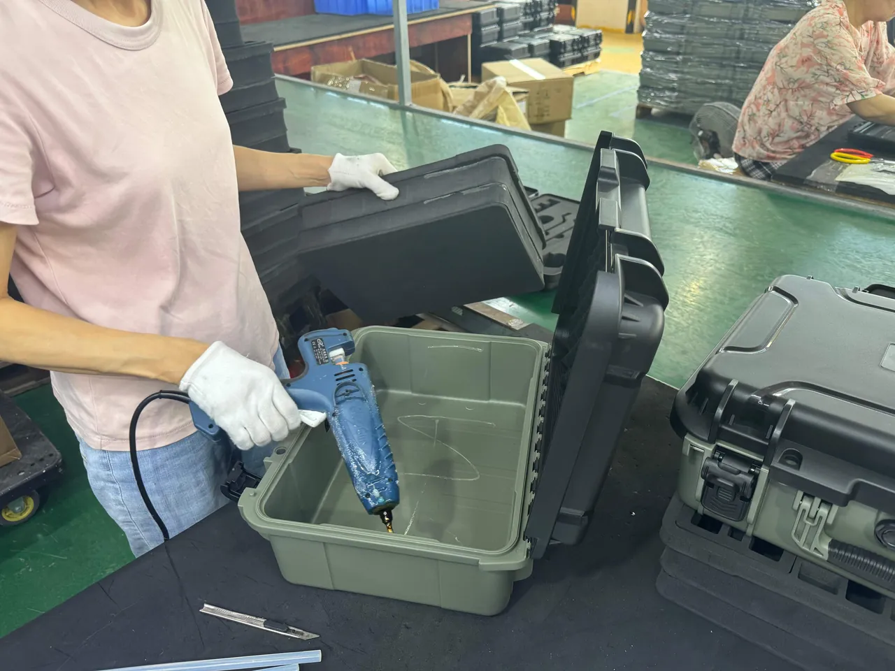
- Production and quality control. Batch sampling with first-article and process records retained.
- Documentation. Material certificates, protection rating statements, test records, packing drawings and label templates.
- Continuous improvement. Inserts and hardware adjusted from field feedback under version-controlled drawings.
When evaluating suppliers, use the criteria in how to choose a protective case OEM factory. Three points matter most: non-standard dimension capability, verifiable test records, and references in the same industry. For tooling amortization, minimum order quantities and lead time structure, see custom case mold cost analysis.
Users should also manage packaging as an asset with finite life. Gaskets harden, foam powders, latches loosen and hinges deform over time. Use protective case service life to set a periodic inspection schedule, with a full assessment typically after 3 to 5 years or more than 200 open-close cycles.
13. Selection Decision Tables and Common Misconceptions
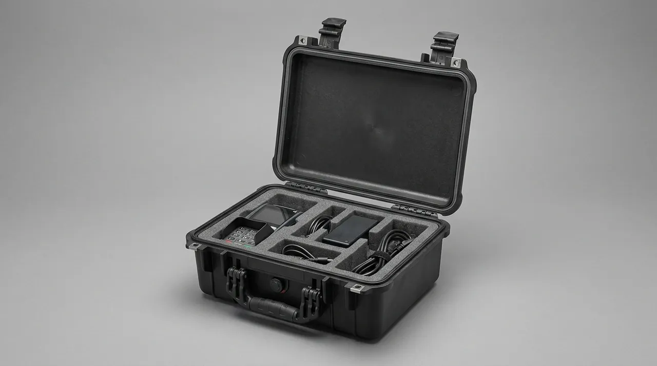
For quick decisions, common scenarios are mapped below.
| Scenario | Component traits | Recommended case | Recommended insert | Key verification |
|---|---|---|---|---|
| --- | --- | --- | --- | --- |
| Small valves below DN50, mixed batch | Light units, many pieces | Mid-size molded case, IP65 | Multi-pocket EVA plus flange caps | Vibration plus opening count |
| DN80 to DN200 ball or gate valves, single unit | Medium weight, critical sealing faces | PP panel with aluminum frame, IP67 | Side-standing location plus suspended flange cradles | Drop plus flange face recheck |
| Valves above DN250 | Heavy, long face-to-face | Heavy aluminum frame or rotomolded case, IP65 | Rigid supports plus multi-point straps | Stacking plus lifting check |
| Valve with electric actuator | High center of gravity, sensitive electronics | Tall-cavity molded case, IP67 | Body bay plus separate accessory bay | Insulation re-test plus humidity check |
| Valve with pneumatic actuator | Large volume, breather ports | Panel case, IP65 | Cylinder profile cradles plus port caps | Vibration plus air port check |
| Relief and precision control valves | High precision, preloaded springs | Molded case, IP67 | Individual compartments plus no-impact marking | Drop plus set pressure records |
| Returned valves for repair | Residual oil, contaminated | Washable case, IP65 | Oil-resistant replaceable insert | Seal integrity plus cleanliness |
Common misconceptions:
- Myth one: wrapping flange faces in plastic film is enough. Film has no impact resistance and wears through under vibration. Use a rigid face cap with soft backing.
- Myth two: the actuator works as a carrying handle. Lateral force on an actuator easily bends the stem or cracks the yoke. Mark lifting points on the case.
- Myth three: valves can be stacked inverted. Inverting makes the stem or accessories the primary load path and can displace internal parts.
- Myth four: accessories can be wrapped with the body. Accessories need their own bay. Contact with a body guarantees damage.
- Myth five: tighter compression is better for seals. Soft seals take a permanent set under sustained compression. Keep them in their natural or factory state.
- Myth six: MIL-STD-810H is a certification. It is a source of test methods, not a certificate.
- Myth seven: one insert design lasts forever. Valve models and actuator brands change. Insert drawings need version control.
Frequently Asked Questions
Q: Why must a petrochemical valve case protect flange sealing faces? Is plastic wrap not enough?
A: Flange sealing faces rely on serrations, the concentric grooves machined into the face, working with a gasket to create a seal. Once serrations are scored by a hard object or flattened by a dent, the gasket cannot fill those defects, and pressure testing after assembly shows weeping. Plastic wrap provides dust protection only. It has almost no impact or compression resistance, wears through on metal corners under vibration, and can be squeezed into the serration grooves as contamination that is very difficult to remove. The correct approach is a plastic or wooden circular cap with a soft backing, snapped or strapped onto the flange so no metal is exposed. For ring joint faces, the cap must have an annular boss that seats into the groove to keep debris out of the groove bottom. Cap materials should be free of sulfur and chlorine to avoid stress corrosion risk in sour service. Flange faces should also be suspended inside the case and never used as a support surface or placed against another flange, because two sealing faces in contact have no protective layer between them.
Q: What goes wrong most often with electric actuators in transit, and how do you prevent it?
A: The most common problem is condensation in the terminal compartment causing a drop in insulation resistance, followed by impacts to the handwheel and display window and lost cable entry plugs. Prevention has four parts. First, plugging: seal cable entries with dedicated plugs or blind plates and fit a desiccant breather or temporary plug to the breather port. Second, dehumidification: place adequate desiccant and a humidity indicator card in the accessory bay, target below 50 percent relative humidity, and for long ocean shipments bag the unit in PE with vacuum or nitrogen per the manufacturer's guidance. Third, impact protection: fit an annular foam guard around the handwheel rim, apply peelable film to the display window, and keep the unit in its own compartment away from the valve body. Fourth, acceptance: make insulation resistance re-test a mandatory opening check and compare against factory records. If the actuator contains circuit boards, also consider static-dissipative insert material and grounding, and never allow the metal valve body and the actuator electronics to share an undivided compartment where vibration can bring them into contact.
Q: What details matter when packing a pneumatic actuator?
A: Three details matter most. First, breather dust protection. If the breather is open during transport, fine dust enters the spring chamber with pressure cycling and can later cause piston sticking or seal wear, so always fit a dust plug or temporary breather cap and remove it only at installation. Second, port protection. Air ports and positioner ports are usually precision threads or quick-connect features that deform under compression, so fit protective caps and keep them free of static load, and coil tubing without sharp bends. Third, spring preload safety labeling. Diaphragm and some piston actuators contain preloaded springs, so the case and accompanying documents should clearly state that untrained personnel must not dismantle the unit, preventing field injury during unpacking. Beyond these, pneumatic actuators are large with an offset center of gravity, so the insert should use profile cradles for the cylinder body and support at multiple points by center of gravity rather than cantilevering. Where the valve and actuator ship assembled, make sure the yoke root has an annular guard so it does not become a stress concentration under lateral vibration.
Q: Should a valve case be IP65 or IP67?
A: It depends on transport and storage conditions. IP65 is dust tight and resistant to water jets, suitable for normal road and rail freight and indoor warehouses, and is the minimum bar for petrochemical valve cases. IP67 adds temporary immersion protection, typically one meter for thirty minutes, and suits ocean export, open yards and wet, humid regions. Use three tests to decide: whether there is a sea leg or open port transshipment, what the destination climate and warehouse conditions are, and how sensitive the contents are. Valves with electric actuators, circuit boards or precision control valve trim strongly favor IP67, while simple gate valves in covered storage can be adequately served by IP65. Note that an IP rating covers solids and water only, not shock, vibration, static or temperature-humidity cycling. Impact resistance still depends on the insert and structural design, and a well-sealed case with a poor insert will still deliver damaged valves. Ratings are defined by IEC 60529 and the equivalent Chinese standard GB/T 4208, and the rating should be stated in the delivery documentation.
Q: Does a packaging case need explosion-proof certification?
A: No, and it should not be requested. A protective case is an outer packaging container, not electrical equipment for explosive atmospheres, so the certification framework of IEC 60079, Chinese GB 3836 or the European ATEX directive does not apply. Packing valves in an IP67 case creates no explosion protection certification, and the fact that valves serve a hazardous area does not imply the packaging needs one. The correct approach is to define the boundary: unpack and hand over at the periphery of the process area, in a warehouse or in a maintenance shop, and mark the case with wording such as not an explosion-proof container, do not open inside a hazardous area, following plant HSE convention. If handling inside a classified area is unavoidable, follow site hot work and static control requirements, and never drag metal case parts across the ground. If packing used valves with residual oil or liquid, hazardous goods packaging rules apply instead. Writing this boundary into the purchase specification stops procurement and HSE from reopening the same question on every order.
Q: How do I choose insert material, and where do EVA and PU each fit?
A: EVA is a closed-cell, CNC-carveable foam across a wide density range, commonly 60 to 120 kg/m3, with tunable stiffness, good weathering and low shedding. It suits applications needing restraint stiffness, such as body location and suspended flange support. PU foam is usually molded in one piece and its rebound behavior absorbs high-frequency vibration energy well, making it suitable for wrapping irregular bodies and building accessory bays, though it can collapse after extended compression and durability is moderate. The common engineering combination is a high-density EVA outer structure for restraint with low-rebound PU in precision contact zones for energy absorption, which is more effective than choosing one material for the whole case. PE foam is low density and low cost, suitable for bedding and filling large parts rather than load-bearing location. Rigid dividers in PP, PVC or plywood handle layer separation and heavy valve support, and should always sit under the heaviest items. Also confirm materials are free of sulfur, chlorine and recycled content, and check compatibility with body coatings and soft seals before approving samples.
Q: Which test standards should a valve case cite, and how are they used at acceptance?
A: Organize along three lines: transport performance, environment and materials. For transport performance, the ISTA series such as ISTA 3A general simulation performance testing and ASTM D4169 distribution cycle sequences are common, while domestic tenders often cite GB/T 4857, which includes stacking, vibration, impact and drop items. For environmental conditions, cite MIL-STD-810H method numbers and levels for vibration, shock and humidity, but state clearly that these are only method sources and do not represent military certification or a full pass. For materials, cite UL94 for case flammability, ISO 9227 neutral salt spray for metal hardware corrosion resistance, and IEC 60529 with GB/T 4208 for ingress protection, and ISO 4406 where hydraulic cleanliness matters. Write these citations into the technical requirement and require suppliers to provide test records and material certificates so acceptance has a documented basis. For valves with electric actuators, add insulation resistance re-testing to the mandatory opening checks, because moisture-induced insulation loss is the single most common arrival defect and is easily caught at goods-in.
Q: What opening checks should be performed when valves arrive?
A: Five steps work well. Step one, appearance and documents: verify case seal numbers, humidity indicator card color, packing list and quality certificates, and confirm the case shows no water ingress traces. Step two, sealing face inspection: compare flange serrations visually and run a dye check if needed, then inspect ball spheres, butterfly seat elastomers and control valve trim for scoring, dents or deformation. Step three, mechanical condition: operate the valve manually to check for sticking, measure stem runout with a dial indicator, and confirm smooth handwheel and actuator operation across the full travel. Step four, actuator specifics: re-test insulation resistance on electric actuators, check pneumatic breathers and air ports for debris or deformation, and inspect positioners, limit switches and accessories for impact damage. Step five, records and disposition: compare all deviations against factory records, judge batch acceptance with a GB/T 2828.1 sampling plan against an agreed AQL, and isolate nonconforming items for supplier analysis. Perform checks in a clean area rather than opening packaging on the process unit where dust and moisture are uncontrolled.
Q: Can one insert hold multiple valves, and does that weaken sealing face protection?
A: Yes, with preconditions. For small valves of similar bore and weight class, a multi-pocket insert with flange face caps is efficient, does not reduce protection, and supports numbered pocket management that speeds counting and issue. Risk appears in two mixing patterns: large weight differences, where heavy valves squeeze light ones under vibration, and inconsistent seal face orientation, where flange faces may contact each other without a protective layer. Three solutions apply. First, layer by weight with heavy valves in their own lower compartments. Second, suspend all flange faces, fit face caps, and prohibit flange faces as supports or in contact with each other. Third, use a removable divider system for stores where models change often, so the layout can be rebuilt without remaking the insert. Either way, run a loaded vibration and drop verification and focus the opening inspection on flange faces and stems to confirm that nothing shifted or contacted anything it should not in the mixed configuration.
Conclusion & Related Reading
The essence of a petrochemical valve and actuator case is translating three engineering constraints into concrete structure and insert language: sealing faces must not be touched, stems must not bend, accessories must not be crushed. IP65 or IP67 handles water and dust, one-valve-per-compartment with suspended flanges handles impact, face caps and stem limits handle sealing surface and stem deformation, separate accessory bays with desiccant handle moisture damage to electronics, and labels with sampling routines handle traceability. Do all five and the high-frequency losses of scored flange faces, bent stems and moisture-damaged actuators fall systematically.
Write the protection rating, insert type, face protection method, test basis and acceptance method into your technical requirement, and require suppliers to provide material certificates and test records. JUNZHJIA, manufactured by Kexin New Materials (Guangdong) Co., Ltd., supports non-standard case design, custom inserts and OEM/ODM volume delivery, and supplies inspection and packing documentation per project so petrochemical users can fold packaging into the spare parts quality system rather than leaving it as evidence in a post-incident dispute.
Related Reading