

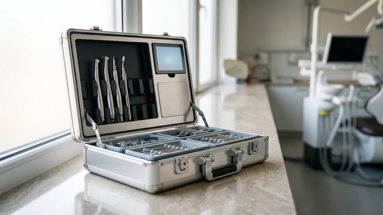
A survey vessel works close to shore, and the underwater camera on board is soaked by sea spray three times a day before being brought into a cabin where mist condenses on it overnight. A documentary team shoots for two weeks in rainforest, fording streams dozens of times with underwater housings and ordinary bodies in the same case. A dive photographer carries gear from a car boot to a fast boat at the dock, and the case takes spray the whole way. What these situations share is that the case is not dealing with one immersion but with a long cycle of wet, salt, pressure and temperature change. A waterproof camera case has to handle that continuous water environment, and the difficulty lies not in wall thickness but in whether the sealing face still holds its designed compression after repeated opening, thermal cycling and salt deposition.
JUNZHIJIA frames the principle for waterproof camera cases as follows: water resistance does not come from a material blocking water, but from one sealing interface holding a stable compression. That interface is made up of sealing face flatness, seal cross-section, compression ratio and the distribution of catch points. If any one of them drifts over time, the rating degrades from its design value to barely holding water out. Acceptance therefore focuses on the dimensions and compression of the sealing interface, and on how fast the seal ages under salt spray, ultraviolet light and low temperature, rather than on appearance.
Table of Contents
- Waterproof Camera Cases and Camera Housings: Two Different Water Problems
- IP67 and IP68: What Depth, Time and Test Conditions Really Mean
- Inside the Sealing System: Sealing Faces, O-Rings and Compression Design
- Closed-Case Testing and Pressure Decay Verification
- How Water Pressure Acts on the Case and How to Control Deformation
- The Role of Pressure Equalisation and Relief Structures in Wet Use
- Condensation Prevention: The Biggest Hidden Risk in Underwater Work
- Drainage, Runoff and Rinsing Design
- Securing Equipment: Buoyancy, Ballast and Movement Suppression
- Long-Term Corrosion from Salt Spray, Chlorinated Water and Seawater
- Tiered Protection for Wet Working Scenarios
- O-Ring and Seal Maintenance Intervals
- Acceptance Criteria, Documentation and Custom Delivery
- Frequently Asked Questions FAQ
- Conclusion and Related Reading
Waterproof Camera Cases and Camera Housings: Two Different Water Problems
The two terms are often used interchangeably, but the physics are entirely different. A camera housing solves the problem of making a camera work underwater: water pressure acts directly on the outside of the housing, so the shell needs enough stiffness to resist external pressure, the optical port needs good transmission and the controls need dynamic seals. A protective case solves the problem of moving and storing equipment safely in a wet environment: the interior normally sees no depth pressure, the main exposures are splashes, short immersion, condensation, salt deposits and stacking, and sealing is predominantly static with no optical port or moving control. A housing is a pressure vessel; a case is a water-resistant container. The two share very few design variables.
That distinction drives selection. Where underwater imaging is the requirement, the user needs a housing and the case only has to get it safely to site. Where the requirement is carrying equipment through rain, on boats and along water crossings, the user needs a case and should not pay the weight penalty of depth-rated construction. Two misapplications are common: putting camera and case into the water expecting to shoot, at which point the sealing face destabilises under pressure; and choosing pressure-rated construction for a rain-sheltered transport job, adding weight and cost with no benefit.
| Dimension | Camera housing | Waterproof camera case |
|---|---|---|
| --- | --- | --- |
| Main load | External water pressure increasing with depth | Splash, short immersion, stacking |
| Seal type | Dynamic plus static | Predominantly static |
| Critical windows | Optical port, button shafts | None |
| Design goal | Depth rating and image quality | Protection rating and transport tolerance |
| Failure consequence | Camera floods and is written off | Equipment damp and corroding |
| Maintenance focus | O-rings and shaft seals | Gaskets and catch points |
For most users the right arrangement gives each product its own job: the housing handles the water, the case handles transport and dry storage ashore, and the case provides a compartment where the housing rests without pressure. This is often missed, yet once a housing's sealing face has taken a permanent set from transit squeezing, dive risk rises noticeably.
IP67 and IP68: What Depth, Time and Test Conditions Really Mean
Under GB/T 4208 and IEC 60529, the second digit of the water protection rating rises from 0 to 8. IPX7 is defined as temporary immersion, typically 1 m for 30 minutes. IPX8 is not defined by specific conditions in the standard: the manufacturer and user agree them, and the conditions must be stated explicitly, for example 10 m for 2 hours or 50 m for 24 hours. This is the most widely misunderstood point about IP68. It is not a fixed depth rating but a "tested and passed under agreed conditions" rating, and two products both labelled IP68 may have been tested under conditions that differ tenfold.
When purchasing, ask for three pieces of information: the test depth and duration, whether the interior was inspected after the test rather than only checked for visible ingress, and whether immersion was static or disturbed. Disturbance creates cyclic pressure variation at the seal and exposes inadequate compression far more readily.
| Rating | Typical test condition | Suited to | Watch out for |
|---|---|---|---|
| --- | --- | --- | --- |
| IPX5 | Water jet | Rain, washing down | No immersion protection |
| IPX6 | Strong water jet | Deck spray | No immersion protection |
| IPX7 | 1 m / 30 min | Short immersion, wet ground | Depth and time are fixed |
| IPX8 | As agreed, for example 10 m / 2 h | Water crossings, boat use | Agreed conditions must be checked |
There is also a practical engineering reality: a sealing face degrades as the seal ages and clamp load relaxes, so a case that passed IPX8 at the factory may behave like IPX5 two years later. The rating is a maintained condition rather than a one-off certificate. Methods for verifying a rating and for spotting false claims are set out in how to verify IP67 certification and differences between IP65, IP66 and IP67.
Inside the Sealing System: Sealing Faces, O-Rings and Compression Design
A static seal has three parts: the groove in the case body, the seal in that groove, and the compression created when the lid closes. They form a series system, so a fault in any one fails the whole. Flatness determines whether contact is even, and injection-moulded parts should be held within 0.3 mm; rotomoulded parts vary more in shrinkage and need a thicker section or a machined sealing face.
Seal cross-section should match the way load is applied. A round O-ring is simple and cheap but can roll out of position under low compression. Rectangular or D-shaped sections locate more stably and suit cases that open and close often. A lipped gasket can use pressure differential to self-energise and seals better when external water pressure exceeds internal pressure, but it loses all benefit if fitted the wrong way round. Hardness usually sits at 55 to 65 Shore A: softer compounds fill microscopic unevenness better, harder ones resist extrusion and abrasion better, and the decision depends on groove clearance and differential pressure together.
Compression is the most critical of the three variables. Designing 25 to 35 percent compression of the seal section height is standard practice. Below 20 percent the seal may not close the microscopic leak path at all, while above 40 percent it accelerates permanent set and makes the case hard to close. Compression is also temperature dependent, because rubber stiffens in the cold and insufficient compression then leaks directly. Groove depth, seal section height and closing clamp load must therefore be closed out together on the drawing rather than specified separately.
| Seal form | Location stability | Self-energising | Assembly tolerance | Best fit |
|---|---|---|---|---|
| --- | --- | --- | --- | --- |
| Round O-ring | Medium | Weak | Low | Small cases, low differential |
| Rectangular section | High | Weak | Medium | Frequent opening |
| D-shaped section | High | Medium | Medium | Mid and large cases |
| Lipped gasket | Medium | Strong | Low | External pressure above internal |
| Dual-lip gasket | High | Strong | Medium | Wet use and immersion |
For wet duty, a dual-lip construction deserves preference, since the first lip blocks direct ingress and the second compensates during pressure variation. The cost is tighter assembly tolerance and more opening resistance, which requires additional catch points to keep compression even.
Closed-Case Testing and Pressure Decay Verification
Type testing of the water rating is done by a third party, but day-to-day delivery and maintenance decisions need something faster. Pressure decay testing is standard practice: pressurise the sealed case to 20 to 30 kPa, close the valve, then record the decay over 60 seconds and reject anything above the set threshold. The physical basis is that a sealing failure shows up as both gas leakage and liquid ingress, and gas molecules are smaller and less viscous, so they reveal small defects sooner than liquid penetration would.
Several details matter. The inflation port needs a reliable one-way valve, otherwise the decay may come from the port rather than the seal. Ambient temperature should be recorded, because thermal change causes false readings. The groove must be clean, since grit or salt crystals create false leak paths, and the test should be run in the real operating attitude because a pressurised lid bows and changes contact at the sealing face.
| Method | Sensitivity | Time | Stage | Limitation |
|---|---|---|---|---|
| --- | --- | --- | --- | --- |
| Pressure decay | High | 1–2 min | Factory, maintenance, arrival | Temperature sensitive |
| Vacuum method | High | 5–10 min | Factory sampling | Needs dedicated equipment |
| Immersion test | Medium | 30 min or more | Type testing | Cannot locate the leak |
| Dye penetrant | Medium | 10–30 min | Fault finding | Destructive, requires cleaning |
| Visual and tactile | Low | Minutes | Before and after each closure | Only finds obvious defects |
The acceptance criterion should be written down rather than judged by feel. Recommended practice is to define the initial pressure, stabilisation time, observation period and permissible decay, and to record the measured value for every case that leaves the factory as a traceable baseline. When decay figures for one model trend upward over time, the seal is ageing and should be replaced before it fails. The relationship between pressure decay and immersion testing, and the criteria for seal replacement, are covered in seal ring replacement and failure diagnosis and case seal ageing criteria.
How Water Pressure Acts on the Case and How to Control Deformation
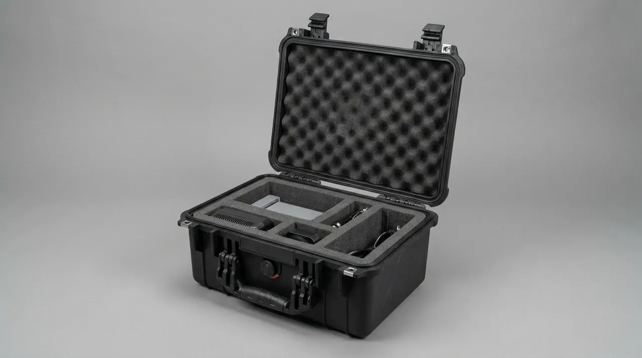
Even where a case never needs depth-rated construction, short immersion and rapid descent still impose external pressure. Hydrostatic pressure rises by about 10 kPa per metre, so a case briefly immersed at 2 m sees roughly 20 kPa, equivalent to about 4.8 kN on a 600 mm by 400 mm lid — enough to bow a thin wall visibly and displace the sealing face, creating a feedback loop where more pressure means more leakage.
Deformation is controlled in three ways. The first is raising overall lid stiffness by arranging a cross-hatched rib network on the inside so the lid behaves as a grid rather than a flat plate, which can multiply bending stiffness several times over. The second is shortening the span from the sealing face to the nearest rib, keeping the groove close to a rigid boundary so relative displacement under pressure is small. The third is controlling deformation of the groove itself, using a reinforcing boss at the groove base or a metal insert so the groove section stays approximately rectangular under load rather than being flattened.
| Immersion depth | Added external pressure | Typical use | Deformation priority |
|---|---|---|---|
| --- | --- | --- | --- |
| 0.5 m | About 5 kPa | Wet ground, rain | Sealing face cleanliness |
| 1 m | About 10 kPa | Short immersion | Groove stiffness |
| 2 m | About 20 kPa | Water crossings | Lid rib network |
| 5 m | About 50 kPa | Overboard deployment | Overall stiffness and latch count |
Sealing and structure are coupled, so acceptance involving immersion should be carried out in the pressurised state rather than measuring groove clearance statically. Immersion reveals whether water enters, but it does not reveal a sealing face that misaligns at a given depth and recovers on the surface, which surfaces later as intermittent ingress. The combined effect of shock and sealing is discussed in combined shock and seal design and system-level IP67 design.
The Role of Pressure Equalisation and Relief Structures in Wet Use
A pressure equalisation valve in a waterproof case performs two apparently contradictory tasks: let gas through, keep water out. It achieves this with a hydrophobic breathable membrane whose pores are far smaller than the smallest water droplet yet far larger than a gas molecule, so air passes and water does not. This matters especially with temperature change: when a case moves from a cool cabin to a sunlit dock, internal temperature and pressure rise, and without a relief path that pressure pushes against the seal, eventually pressing it into the groove and leaving a permanent set.
In wet use the valve's location and detailing matter more than its specifications. It should sit high on a side wall, with a baffle or labyrinth so water cannot strike the membrane directly, and it should not sit at the lowest point of an upright case, where it would remain immersed in a salt-bearing film. Membrane fouling is gradual: grease, silt and salt crystals progressively block the micropores, reducing air flow in a way that is hard to notice, so the valve belongs on the scheduled inspection list, as described in pressure equalisation valve operation and selection.
Another structure that is easily overlooked is drainage. The exterior should avoid pockets and blind recesses that hold water, particularly on the base and at corners, and where the geometry makes this unavoidable, drains or runoff slopes should be provided. Internally the opposite applies: the liner should avoid fully closed cavities, so any water that does enter can be captured by an absorbent layer or desiccant.
Condensation Prevention: The Biggest Hidden Risk in Underwater Work
In wet and underwater photography the most frequent cause of damage is not ingress but condensation. Equipment sits for hours in a cool morning or an air-conditioned cabin, so case and contents are cold; the case is then carried to a damp waterside where the ambient dew point exceeds the surface temperature, and water vapour condenses immediately on housings and lens elements. Opening the case at that moment makes it worse. The damage is delayed: that day there may only be fogging, and days later mould and corroded circuits appear.
Three levers control condensation. The first is sealing plus desiccant: equipment goes in dry, and desiccant is sized to net internal volume, typically 10 to 20 g of silica gel per 10 L, with wet-duty cases taking the upper figure because repeated openings consume more. The second is thermal transition: do not open the case immediately on moving from cold to damp, but let it stand so surfaces rise above the dew point before opening; where work must continue, open the case in shade with airflow and lower humidity. The third is humidity monitoring: fit a card graduated from 10 to 60 percent, read it before unpacking, and treat a reading above 40 percent as evidence that internal humidity management has failed.
Desiccant has limits: silica gel holds less moisture as temperature rises, and saturated gel does not regenerate by itself. For continuous wet work, a twin dry-compartment strategy helps, with a small replaceable well holding the desiccant so the main compartment is never exposed during a change, and daily rather than weekly replacement.
Drainage, Runoff and Rinsing Design
Rinsing after wet work is central to long-term reliability, especially with seawater and chlorinated water. Salt left in the groove crystallises, and the crystals are pressed into the seal surface when the lid closes, leaving permanent indentations, while chloride attacks hardware and metal inserts. The structure must therefore support cleaning: the groove should be reachable with a soft brush, its base should have no dead corner, the base ribs should direct water out rather than forming puddles, and hardware should avoid capillary gaps.
A fixed rinsing sequence is worth adopting. First flush surface silt with low-pressure fresh water, avoiding a high-pressure jet aimed at the groove or valve, because the dynamic pressure of a jet far exceeds immersion pressure and can drive water past the seal. Then clean the groove with a soft brush and neutral detergent. Then rinse and blot with a soft cloth. Finally let everything dry completely in ventilated air before closing. When rinsing at the waterside, take particular care never to close the case while the sealing face is still wet, because the residual film lets the seal slide and be pushed out of position as the lid closes.
| Step | Purpose | Key point | Common error |
|---|---|---|---|
| --- | --- | --- | --- |
| Initial rinse | Remove silt and salt | Low pressure, avoid the groove | High-pressure jet at the sealing face |
| Groove cleaning | Remove crystals and debris | Soft brush with neutral detergent | Scraping with metal tools |
| Hardware check | Catch early corrosion | Shafts, springs, contacts | Ignoring hidden gaps |
| Drying | Avoid trapping a water film | Full drying with ventilation | Closing while still wet |
| Seal conditioning | Restore elasticity | Follow the material specification | Using incompatible grease |
Seal conditioning must match the material: silicone rubber suits silicone grease, nitrile and EPDM tolerate mineral oil differently, and the wrong choice causes swelling or hardening. The general rule is not to apply grease unless the supplier specifies it, because grease traps grit.
Securing Equipment: Buoyancy, Ballast and Movement Suppression
Wet use adds two physical requirements to equipment retention: buoyancy and movement. Underwater housings and some items contain air and are positively buoyant, so if a case goes overboard, the internal buoyancy and the case's own weight together decide its floating attitude. Some operations require the case to float recoverably, which may need ballast adjustment so it floats with the opening upward. Such requirements must be raised early, because ballast position directly affects liner layout.
Movement suppression follows the same rules as transport but is more demanding: boat motion is low-frequency, large-amplitude and continuous, and it lets equipment travel far inside a compartment. The answer is at least two support points straddling the centre of gravity, a compression face for light bulky items such as housings, and a separate low-mounted compartment for heavy items. Wet work also means wet hands, so frequently used items should not sit high in the case where a fumble becomes a fall.
Related designs carry across from camera transport and are covered in configuring a camera equipment case, choosing a photography equipment case and machine vision camera cases.
Long-Term Corrosion from Salt Spray, Chlorinated Water and Seawater
Seawater attacks the metal parts of a case most of all. The seal is usually rubber and reasonably salt tolerant, but hinge pins, latch springs, inner handle tubes, metal inserts and the valve body can corrode within weeks. Under the GB/T 10125 neutral salt spray test, common durations are 48, 96, 240 and 480 hours, used to compare corrosion tendencies. For seawater duty the usual mapping is 304 for inland work and 316 for coastal, boat-borne and seawater-exposed use, with plating or coating where material cannot change, and particular attention to edge coverage.
Chlorinated water, from pools and water treatment facilities, corrodes differently but is equally dangerous: hypochlorite accelerates pitting in stainless steel, especially in crevices. Crevice corrosion appears where metal meets plastic, under screw heads and at the boundary between the groove and a metal insert. The design answer is to reduce crevices by moulding inserts in or filling with sealant, rather than simply thickening the coating.
| Environment | Main corrosive agent | Recommended metal | Supplementary measure |
|---|---|---|---|
| --- | --- | --- | --- |
| Inland, rain | Oxygen, carbonate | 304 | Standard plating |
| Coastal, boat-borne | Chloride | 316 | Regular fresh water rinse |
| Pool, chlorinated water | Hypochlorite | 316 or plastic parts | Avoid crevices, rinse promptly |
| Seawater immersion | High chloride | 316 with coating | Rinse and dry immediately after use |
| Hot spring, geothermal | Sulphide | 316 or titanium | Specialised seal material |
Salt spray testing is a ranking and screening method for comparing schemes; it cannot be extrapolated directly to service life and does not support any certification claim. Additional requirements for sea freight and long storage are covered in sea freight notes for outdoor cases.
Tiered Protection for Wet Working Scenarios
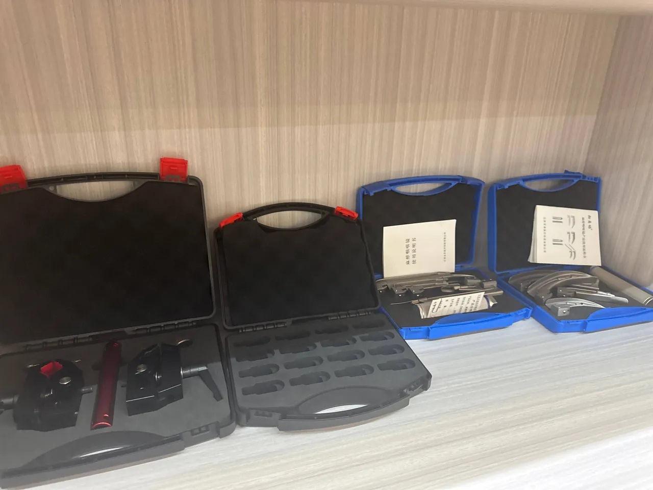
Requirements vary widely across wet scenarios, and tiering them prevents both over-design and under-protection. The lightest tier is wet hands and splash, such as shooting in rain or spray on a boat, where the priority is seal condition and surface drainage. The second tier is intermittent immersion, such as resting a case in shallow water or recovering it after it goes overboard, where the priority is compression stability and catch point count. The third tier is short-duration deep immersion, such as overboard deployment or rapid descent, where the priority is lid stiffness and groove deformation under pressure. The fourth tier is sustained on-water work, such as several consecutive days afloat, where the priorities shift to seal ageing rate, hardware corrosion resistance and the rinsing and maintenance routine.
Tiering puts resources where the bottleneck sits. Designing a tier three case for a tier one application makes it heavy and awkward to open, while treating a tier four application as tier one lets the seal fail within weeks.
| Tier | Example scenario | Main bottleneck | Critical design item |
|---|---|---|---|
| --- | --- | --- | --- |
| One: splash | Rain, boat spray | Sealing face cleanliness | Drainage, reachable groove |
| Two: intermittent immersion | Shallow rest, overboard recovery | Compression stability | 25–35 percent compression, catch count |
| Three: short deep immersion | Overboard deployment, fast descent | Structural stiffness | Lid rib network, groove stiffness |
| Four: sustained on-water work | Days afloat, daily seawater | Ageing and maintenance | 316 hardware, maintenance schedule, twin dry wells |
Wet protection is not limited to photography; industrial and water treatment applications have similar needs, covered in waterproof box applications and the IP65 field test for waterproof toolboxes.
O-Ring and Seal Maintenance Intervals
The seal is the classic consumable. Ageing is driven by temperature, ultraviolet light, chemical media and mechanical compression. Heat accelerates oxidative cross-linking, making rubber hard and inelastic; ultraviolet breaks surface polymer chains and forms fine cracks; salt, chlorine and grease cause swelling or extraction; and sustained compression produces permanent set so the seal no longer recovers its original section height. Combined, these give an effective life of two to three years, adjusted for use intensity.
Three practical criteria decide replacement. For appearance: visible cracking, hardening, a glossy surface indicating plasticiser migration, or noticeably sluggish rebound after compression. For dimensions: after removal and 24 hours of relaxation, measure the section height, and if it is still below 90 percent of the original, the set is irreversible. For function: pressure decay beyond threshold within 60 seconds at 20 to 30 kPa, or intermittent ingress in service.
Three actions must accompany any replacement: inspect the groove for scratches, burrs or corrosion pits, since groove damage cannot be fixed by a new seal; check whether groove dimensions have distorted under long compression; and repeat the pressure decay test afterwards, recording it to build a maintenance history. Replacement and selection details appear in outdoor case seal ring selection and waterproof versus standard junction boxes.
| Maintenance item | Interval | Criterion | Action |
|---|---|---|---|
| --- | --- | --- | --- |
| Sealing face cleaning | After each wet use | Silt, salt crystals | Soft brush and fresh water rinsing |
| Seal visual check | Monthly | Cracks, hardening | Record and schedule replacement |
| Pressure decay test | Quarterly | Decay above threshold in 60 seconds | Replace the seal |
| Seal replacement | 2–3 years | Rebound below 90 percent | Replace and retest |
| Hardware inspection | Quarterly | Rust marks, stiffness | Clean or replace |
| Desiccant replacement | Per indicator card | Reading above 40 percent | Replace and inspect the seal |
Acceptance Criteria, Documentation and Custom Delivery
Acceptance of a waterproof camera case should centre on the sealing interface rather than stopping at appearance. Recommended checks include sampling sealing face flatness, held within 0.3 mm for injection-moulded parts; verifying seal section dimensions and hardness against the drawing; measuring compression from the change in section height before and after closing, confirming it falls between 25 and 35 percent; confirming catch point count and distribution; recording a 60-second pressure decay figure; and checking valve breathability by light blowing or flow measurement. On appearance, focus on scratches in the groove, a dished lid and rust on hardware.
Documentation should include a seal specification and replacement schedule, factory and arrival pressure decay records, a rinsing and maintenance card, desiccant quantity and indicator readings, and inspection points for valve and hardware. Wet-protection failures are usually gradual, so only continuous records show whether performance is degrading.
Custom delivery covers compartment layout separating the housing from the bodies, hardware upgrades from 304 to 316 or substitution with plastic parts, and the positioning of valves and dry compartments. Contract clauses on protection level, test conditions and acceptance method should be explicit, and the depth and duration behind an IP68 claim must be a verifiable number; see custom case contract IP clauses and custom case MOQ baseline.
Frequently Asked Questions FAQ
Q: Can a waterproof camera case be taken underwater for shooting?
A: No, because the two problems are physically different. A protective case is a water-resistant container designed to block splash, short immersion and condensation, and it normally has no optical port or control mechanism inside. Underwater shooting needs a housing, which is a pressure vessel with enough stiffness to resist external water pressure and which carries an optical port and dynamic shaft seals. If a camera is put into the water inside a case expecting to shoot, the sealing face will displace under pressure: at 2 m depth a case lid sees roughly 20 kPa, equivalent to about 20 kN per square metre, which is enough to bow a thin wall and pull the sealing face out of alignment. The correct division of labour gives the housing the water and the case the transport and the dry storage ashore. For boat-based work, the housing should also travel with its port facing upward and a soft pad between the port and the liner, since a scratched port is an expensive repair even when nothing has flooded.
Q: Is IP68 stronger than IP67, and is deeper always better?
A: Not in the way it is usually assumed. IPX7 is defined by the standard: 1 m for 30 minutes. IPX8 is not defined by the standard at all; the manufacturer and user agree the conditions and must state them in the documentation, for example 10 m for 2 hours or 50 m for 24 hours. Two cases both labelled IP68 may therefore have been tested under conditions differing tenfold, and comparing the rating alone is meaningless — the test conditions must be compared. Ask for three pieces of information: the test depth and duration, whether the interior was inspected after the test, and whether immersion was static or disturbed. Disturbed testing creates cyclic pressure variation at the sealing face and exposes inadequate compression far more reliably. Where a supplier cannot state the conditions, treat the rating as unverified whatever the label says, and ask instead for a factory pressure decay record measured at a defined pressure and observation time. That record is a measurable, repeatable number rather than a claim.
Q: The case passed its immersion test, so why does it still leak in service?
A: The usual reason is that the test condition and the service condition differ, with seal ageing as the second cause. Immersion tests are typically static, with a clean sealing face and at room temperature, whereas service involves pressure variation, grit or salt crystals on the sealing face, and lower compression because rubber stiffens in the cold. Repeated opening also leaves permanent set in the seal, so two years on the compression may already be below the design value and the case will leak even though it looks sound. Make pressure decay testing the routine criterion: a 60-second decay above threshold at 20 to 30 kPa means the seal needs replacing, and the groove should be checked for scratches and debris at the same time. A useful discipline is to write the decay figure on a label inside the lid after every test, so the trend is visible without consulting a database: a seal that held 25 kPa for a minute when new and now loses 8 kPa in the same minute is telling you exactly when to act.
Q: How should a case be cleaned after seawater use, and can a pressure washer be used?
A: Never point a pressure washer at the sealing groove or the valve. The dynamic pressure of a jet greatly exceeds immersion pressure, and it can drive water past the seal or momentarily displace it. The correct sequence is to flush surface silt and salt with low-pressure fresh water, keeping the jet away from the groove; clean the groove with a soft brush and neutral detergent to remove crystals and debris; rinse and blot with a soft cloth; and allow complete drying in ventilated air before closing. In particular, never close the case while a water film remains on the sealing face, because the film lets the seal slide and be pushed out of position, creating a long-term defect that will not show up until the next immersion. Where fresh water is unavailable, a final wipe with a damp cloth and a full dry before closing is far better than leaving salt in place, and hardware should be inspected during the same routine because spring and shaft corrosion is much easier to catch early.
Q: With desiccant in the case, can condensation still occur?
A: Yes. Desiccant lowers the moisture content of the air inside the case but does nothing about temperature difference, and condensation depends on surface temperature relative to the dew point rather than on absolute humidity. When a case moves from a cool environment into warm humid air, surfaces inside can still fall below the dew point even with desiccant present, particularly after hours in an air-conditioned cabin followed by a move to the waterside. The effective approach combines thermal transition — standing the case until its surfaces rise above the dew point before opening, and working in shade with airflow — with desiccant that handles long-term storage and any moisture already inside. The two measures are complementary and neither replaces the other. Logging the indicator reading on arrival also reveals whether the case is absorbing moisture during transport or only at the moment of opening, and a slow upward trend across several trips means the seal is losing compression, which calls for a service action rather than an operational one.
Q: How often should the seal be replaced, and how do I judge whether it is due?
A: Two to three years is the usual recommendation, or a defined closure cycle limit, with the actual interval depending on intensity and media. Three workable criteria apply. Visually, look for cracks, hardening, a glossy surface or sluggish rebound. For dimensions, remove the seal, let it relax for 24 hours and measure the section height; below 90 percent of the original means the set is irreversible. Functionally, a pressure decay test above threshold within 60 seconds at 20 to 30 kPa, or intermittent ingress in service, both indicate replacement. Whenever the seal is replaced, inspect the groove for scratches and corrosion pits at the same time, because groove damage cannot be corrected by fitting a new seal. Keep a record of the replacement date and the measured compression as well, because the interval that suits a case used twice a season is far longer than one used weekly in salt water, and the record turns that judgement into a number that can be reviewed at the next service.
Q: For wet use, should I specify 304 or 316 stainless steel?
A: It depends on the medium and the frequency of exposure. For inland and ordinary outdoor duty, 304 is generally sufficient. For coastal work, boat-borne use and regular seawater contact, 316 is advisable, because molybdenum markedly improves resistance to chloride pitting. Pools and chlorinated water carry hypochlorite risk, so 316 or plastic substitution is preferable, and crevice corrosion deserves particular attention: metal-to-plastic interfaces, under screw heads and the boundary between groove and metal insert are all high-risk locations. Moulding inserts in or filling with sealant is more effective than thickening the coating. Where cost pressure is real, the pragmatic compromise is to specify 316 only for the parts that stay wet longest, such as hinge pins, latch springs and the valve body, rather than upgrading every screw in the case. In practice the highest-risk locations are the hinge pin, the latch spring and the valve body, because all three stay wet far longer than the case exterior. Salt spray testing only compares corrosion tendencies; it cannot be converted into service life and does not constitute certification.
Q: How can I tell whether a waterproof case really meets the rating it claims?
A: Check three levels. At document level, ask for a third-party test report and confirm it states the test depth, duration, method and the inspection conclusion after testing. At product level, verify that seal section dimensions, hardness and compression match the drawing, that catch point count and distribution match the design, and that a pressure decay record exists for each case. At service level, keep traceable arrival acceptance and periodic retest records, and when decay figures for one model trend upward, treat it as evidence that the seal is ageing and replace it early. All three matter: an IP68 label without stated conditions cannot be compared, and an immersion test with no internal inspection conclusion only proves that nothing obvious was found at the time.
Conclusion and Related Reading
The technical core of a waterproof camera case is one sealing interface that works consistently.
Related Reading