

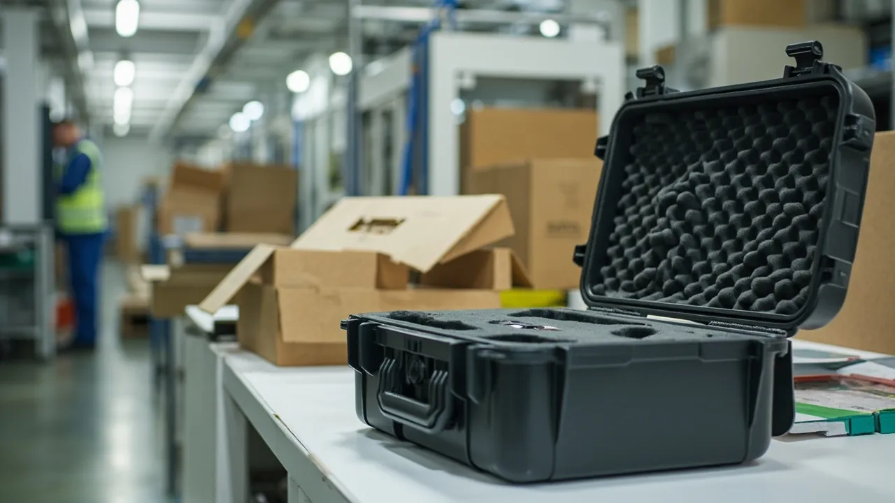
Spares for a corrugated box print-slot die-cutter — plate cylinders, ceramic anilox rollers, doctor blades, slotting knife holders, curved rotary die boards, anvil covers and feed rollers — combine precision machined faces, coated functional surfaces and high-speed rotating fits. The core threats during transport and storage are functional-surface scratching, coating spalling, edge dulling, roll bending and corrosion. The selection logic for corrugated packaging machinery cases must therefore follow three threads: zero-contact protection of functional surfaces, vibration and dust exclusion, and rust and moisture prevention — not the logic of an ordinary tool box. One characteristic of this industry stands out: replacement is driven by order flow, box plants change jobs frequently, and roll, die and knife changes are squeezed into very short windows between shifts. Spares must therefore not merely arrive, but arrive install-on-open and work-on-install. The corrugated production environment is itself dusty and full of paper lint, and the paper dust and starch adhesive powder in the air settle on precision surfaces; once carried into a mating face, they cause wear and print quality drift.
The pain points are characteristic. The anilox roller is the highest value and most fragile single item on the machine. Its surface is a ceramic coating laser-engraved with tens of thousands of cells; a single impact from a hard object spalls the coating, the cells around the spall deform, and the result is an abnormal ink transfer rate in that band that prints as a constant-position ink density difference. Anilox rollers are also vulnerable to any scratching and contamination, and cleaning with the wrong tool causes irreversible damage. Plate cylinders and plate mounting faces suffer from impact, corrosion and deformation: the plate slot, locating face and runout accuracy determine register, so a gouged shell or a deformed plate slot produces poor plate seating and register drift, and the cylinder is a slender item that bends under inadequate support. Doctor blades are thin steel precision items whose edge cannot be nicked, rolled or rusted if ink metering is to stay uniform; once damaged the blade is replaced as a whole. Slotting knife holders and slotting knives determine slot position accuracy through their edge and locating precision, and a dulled edge produces fuzzy cuts and dimensional error. Curved rotary die boards must match the die roll diameter exactly; their wood or polymer base is vulnerable to moisture deformation and compression cracking, and the cutting and creasing rules are vulnerable to impact deformation. Die boards are usually custom-made, so a damaged board means remanufacture and a delivery lead time, with line stoppage cost far exceeding the value of the die. Anvil covers and feed rollers are rubber items vulnerable to permanent compression set, oil contamination and ageing by ultraviolet and ozone. Bearings and servo drive components in the printing and feed sections are precision items vulnerable to dust ingress and vibration shock.
This article sets out protection logic in the order of printing section, slotting section, die-cutting section and feed and stacking sections. It focuses on four schemes — dedicated protection for ceramic coatings, precision load bearing for dies and rolls, deformation-free storage of rubber items, and vibration, rust and dust control — and includes component protection tables, a method for determining sealing class, transport test items and acceptance criteria. JUNZHJIA serves corrugated packaging machinery manufacturers, box plants, packaging equipment distributors and die-tooling suppliers with precision case design, custom inserts, sealing and rust-prevention schemes matched to each component, and OEM/ODM volume delivery, manufactured and shipped worldwide by Kexin New Materials (Guangdong) Co., Ltd.
Table of Contents
- 1. Why Corrugated Packaging Machinery Spares Need Purpose-Built Cases
- 2. Risk Profile for Print-Slot Die-Cutter Spares: Precision, Cleanliness, Fast Change
- 3. Protecting Printing Section Components: Plate Cylinders, Anilox Rollers, Blades
- 4. Protecting Slotting Section Components: Knives, Holders and Paper Guides
- 5. Protecting Die-Cutting Section Components: Rotary Dies, Covers and Anvils
- 6. Protecting Feed and Stacking Section Components
- 7. A Dedicated Protection Scheme for Ceramic Anilox Rollers
- 8. Precision Protection for Rotary Dies and Creasing Rules
- 9. Vibration, Dust and Sealing: IEC 60529 and GB/T 4208
- 10. Rust and Moisture Prevention: Steel and Coated Parts
- 11. Custom Inserts: Rolls, Die Boards and Thin Components
- 12. Transport Testing: ISTA, GB/T 4857 and ASTM D4169
- 13. Fast-Change Spare Management and Shutdown Window Alignment
- 14. Procurement Acceptance, AQL and Specification Selection Table
- 15. Export and OEM/ODM Delivery Points
- Frequently Asked Questions
- Conclusion & Related Reading
1. Why Corrugated Packaging Machinery Spares Need Purpose-Built Cases
Corrugated box manufacturing has a distinctive operating characteristic: fragmented orders, high job-change frequency and extremely short changeover windows. Demand fluctuation from e-commerce and consumer packaging means a box plant may complete several job changes in a single day, and each change involves swapping printing plates, adjusting slotting knife groups and fitting a different die. Equipment availability directly determines delivery capability, so spare management aims not at holding stock but at being ready to change and ready to run.
Functional surfaces carry the value of the whole machine. The accuracy chain of a print-slot die-cutter is a series of critical faces: the anilox cell pattern sets ink transfer, the plate cylinder mounting face and runout set register, the slotting knife edge sets slot dimensions, the die cutting and creasing rules set box accuracy, and the anvil cover sets die-cut quality. What these surfaces share is that their tolerances run from microns to tenths of a millimetre and damage is not repairable. A spalled ceramic coating on an anilox roller cannot be locally repaired, only reworked at the factory or replaced; a deformed plate slot cannot be adjusted back to original accuracy; a bent die rule can only be replaced or the whole die remade. The design objective for a parts case is therefore unambiguous: let every non-functional surface carry the entire load, and let functional surfaces never contact a hard material.
Environmental dust is an inherent challenge in a corrugated plant. Corrugated board production generates large volumes of paper chips, lint and starch adhesive powder. These particles are small, numerous and often electrostatically charged, and they settle on case surfaces and in seal channels. If the case seal does not exclude them effectively, they enter and deposit on anilox cells, plate cylinder mounting faces, holder mating faces and bearing seats. Starch adhesive powder becomes sticky once it takes up moisture and glues the particles onto precision surfaces, accelerating wear. A corrugated industry parts case must therefore combine dust-exclusion sealing with a cleanable seal structure.
The urgency of the changeover window means packaging must support fast work. Roll and die changes in a box plant are scheduled into shift gaps, and the operator has to complete removal, retrieval, installation and adjustment in limited time. If opening the case, retrieving the part and checking it off are cumbersome, or if the part is over-secured and difficult to extract, the result converts directly into downtime. The latch mechanism, the insert retrieval method and the internal labelling organisation are therefore functions rather than accessories and must be considered at the design stage.
In summary, the three core requirements for a corrugated packaging machinery case are a functional-surface-centred zero-contact insert design, effective sealing and a cleanable structure for a dusty environment, and latch and labelling organisation that supports fast retrieval. A general selection framework is set out in the Instrument case selection guide.
2. Risk Profile for Print-Slot Die-Cutter Spares: Precision, Cleanliness, Fast Change
Spare logistics for a corrugated print-slot die-cutter has a particular shape: parts ship from the machine builder or the die-tooling supplier through a regional warehouse or distributor, or directly to the box plant, may pass through several transfers and long storage, and end their journey being fitted inside a shutdown window.
| Chain stage | Dominant stress | Typical consequence | Protection focus |
|---|---|---|---|
| --- | --- | --- | --- |
| Manufacturer dispatch | Long-distance vibration, stacking | Roll bending, die deformation | Rigid support, one part per compartment, static verification |
| Regional warehouse and distributor storage | Sustained static load, humidity, dust | Corrosion, rubber ageing, coating contamination | Sealing plus desiccant plus rust prevention |
| Box plant spare store | Dust, repeated retrieval | Cell contamination, mating-face wear | Cleanable sealing, fast latch, position marking |
| In-plant move to the machine | Short-range vibration, impact | Coating spall, rule nicks | Dedicated cavities, soft isolation, handling marking |
| Export and cross-border delivery | Sea-freight humidity, repeated handling | Corrosion, condensation, case damage | IP67 plus desiccant plus stacking strength |
Vibration is the main threat to rolls and dies. Plate cylinders and anilox rollers have large length-to-diameter ratios and their accuracy metrics are roundness and runout. Supporting only at the two ends and leaving the middle unsupported allows transport vibration to bend the body, which appears on the machine as excessive runout and uneven printing pressure. A curved rotary die board is a thin-walled curved item that has no inherent bending stiffness and must rely on contoured support to preserve its curved profile; inadequate support deforms the arc and shifts die-cut position after installation. Both classes need rigid support, one item per compartment, and removal of displacement freedom.
Cleanliness is a constraint specific to the anilox roller. Cell volume determines ink transfer, and any foreign matter occupying a cell reduces actual transfer. Dust, oil, hand grease and fragments of packaging material can all block cells locally. Worse, if ordinary paper or timber packaging is used, its fibre debris sheds continuously and transfers to the roll surface. Anilox packaging materials must therefore satisfy no-dust, no-release and no-shedding requirements.
The fast-change rhythm imposes a retrieval efficiency requirement. A roll change in a box plant requires the operator to find the right component quickly and accurately. Mixed contents and unclear labelling leave the operator searching inside a tight window, which both extends downtime and risks secondary damage from rushed handling. Internal position marking and status management are therefore direct levers on equipment availability.
3. Protecting Printing Section Components: Plate Cylinders, Anilox Rollers, Blades
The printing section determines corrugated print quality and carries the highest precision requirements.
Ceramic anilox rollers are among the most valuable single items on the machine. The surface is a ceramic coating laser-engraved with a regular cell pattern in hexagonal, diamond or other arrangement, metering ink by volume. Key parameters include cell count per inch or per centimetre, cell volume, coating thickness and surface roughness. Failure modes include coating spall from a hard impact, where the ceramic detaches locally and surrounding cells deform, producing constant-position ink density faults; surface scratching from using metal scrapers during cleaning or handling; cell blockage from dried ink or dust, reducing transfer volume; body bending from inadequate support, degrading pressure uniformity; and corrosion at uncoated ends and shaft ends. Anilox protection is therefore treated separately in Section 7.
Plate cylinders carry the flexible printing plate and feature a plate slot, locating faces and tensioning structure. Failure modes include impact and corrosion on the mounting face, producing poor plate seating and register drift; plate slot deformation disabling the plate lockup; body bending producing excessive runout; and keyway and shaft end damage. Protection requires a soft cover over the mounting face with no load applied, protective filling of the plate slot to keep foreign matter out, rigid support and dust and rust protection at shafts and bearing seats, and full roll restraint in the actual attitude with rolling freedom removed.
Doctor blades and blade chambers are thin steel precision items. Blade edge flatness determines ink metering uniformity and anilox wear; an edge that is rolled, nicked, corroded or deformed cannot form a uniform film. Protection requires a protective cover over the edge with no contact against any hard material, flat storage on a flat support to prevent bowing, a dedicated clamping fixture to prevent free deformation, and dust protection for the chamber seals and mating faces.
Other precision items in the printing section include ceramic rollers, ink transfer rollers, ink pumps and ink circuit components, servo motors and encoders. Ink pumps and circuit components contain seals vulnerable to drying and contamination. Servo motors and encoders are precision electrical items vulnerable to vibration and dust and should follow a precision instrument protection scheme; see the IP67 protective case solutions.
| Printing section component | Main failure mode | Protection strategy | Critical prohibitions |
|---|---|---|---|
| --- | --- | --- | --- |
| Ceramic anilox roller | Coating spall, surface scratch, cell blockage | Dedicated soft cover, rigid shaft-end support, dust sealing | No hard contact with the face, no metal scrapers |
| Plate cylinder | Mounting face impact, slot deformation, bending | Soft face protection, slot filling, equally spaced support | No load on mounting face, no unsupported mid-span |
| Doctor blade | Edge rolling, nicking, corrosion | Edge protector, flat support, dedicated cavity | No hard contact with the edge, no bending load |
| Ceramic and transfer rollers | Surface scratch, shaft damage | Soft cover, rigid shaft support | No stacking, no load on working face |
| Ink pumps and circuit parts | Drying, contamination, seal failure | Dedicated sealed cavity, port plugging | No shared cavity with dusty items |
| Servo motors and encoders | Vibration damage, dust ingress | Precision instrument insert, static protection | No drop or shock |

4. Protecting Slotting Section Components: Knives, Holders and Paper Guides
The slotting section cuts the slots and creases required for box forming, and its accuracy directly determines box dimensions and fold quality.
Slotting knives and blades are edged items whose edge angle and sharpness determine cut quality. Failure modes include edge nicking and rolling from impact or misuse, producing fuzzy cuts and board tearing; corrosion, which increases friction and roughens the cut; and blade deformation in thin components under compression. Protection requires a protective cover over the edge, flat storage on a flat support with soft isolation, individual packing so edges cannot contact each other, and corrosion protection with desiccant.
Slotting knife holders and knife shafts are precision fits carrying blade locating slots and locking structure. Locating accuracy determines slot position repeatability. Failure modes include impact and wear on locating faces, deformation of the locking structure, shaft bending and corrosion. Protection requires soft protection on locating faces with no load applied, dedicated cavities so holders cannot strike each other, equally spaced support for shafts with rolling restraint, and corrosion protection.
Knife shafts and drive gearing combine long components with transmission parts. Shaft accuracy requires roundness and runout; gearing requires mesh accuracy. Protection requires multi-point shaft support, tooth-flank protection against impact and corrosion, and separation of finished from semi-finished parts.
Paper guides and creasing wheels include guide plates, creasing wheels and creasing shafts. The creasing wheel profile determines crease quality, and once the profile is nicked it produces a defective crease. Protection requires contoured protection of the profile, dedicated cavities for wheels, and protection of axial locating faces.
| Slotting section component | Main failure mode | Protection strategy | Critical prohibitions |
|---|---|---|---|
| --- | --- | --- | --- |
| Slotting blade | Edge nick, rolling, corrosion | Edge protection, flat support, individual isolation, rust prevention | No hard contact with the edge |
| Slotting knife holder | Locating face impact, lock deformation | Soft protection, dedicated cavity, unloaded locating face | No load on locating face |
| Knife shaft | Bending, journal damage, corrosion | Equally spaced support, journal protection, rolling restraint | No unsupported mid-span |
| Drive gearing | Tooth flank impact, corrosion | Flank protection, rust prevention, dedicated cavity | No flank-to-flank contact |
| Creasing wheels and guides | Profile impact, deformation | Contoured protection, unloaded profile | No load on profile |
5. Protecting Die-Cutting Section Components: Rotary Dies, Covers and Anvils
The die-cutting section carries some of the highest precision requirements on a corrugated print-slot die-cutter, and its spares are mostly custom items with long lead times and high value.
Curved rotary die boards are the central die-cutting spare. A die board consists of a base — wood or polymer — with steel cutting rules and creasing rules set into it, pre-curved to match the die roll diameter. Failure modes are unambiguous: moisture deformation of the base, where a wood base swells and changes the arc radius so that die-cut position shifts or pressure becomes uneven; compression cracking of the base from inadequate support or stacking; rule deformation, where impact bends the cutting rule, nicks the edge or topples the creasing rule; and rubber ejection strip detachment. Protection requires strict moisture exclusion, since the wood base is extremely humidity-sensitive and needs a high sealing class with desiccant; contoured rigid support, with the support face following the curved profile rather than point contact; rule protection, with no hard contact anywhere in the rule zone and a relief structure provided; and individual storage, with die boards never touching each other.
Anvil covers directly determine die-cut quality. The cover receives the cutting rule during die-cutting, and its surface flatness and hardness uniformity determine cut quality and cover life. Failure modes include permanent compression set from point support or stacking, accumulated surface indentation and cut marks, oil contamination, and ageing by ultraviolet and ozone that hardens and cracks the rubber. Protection requires that the cover never carries any point or concentrated load, that it be laid flat on a large-area flat support, that storage avoid light and heat, and that it be kept free of oil.
Anvil and die rolls are large precision rolls with mounting faces and mating structure. Protection requires soft protection of mounting faces, equally spaced rigid support at shaft ends, rolling restraint, dust and rust protection, and moisture-proof wrapping.
Auxiliary die-cutting items include stripping components, ejection rubber, paper guides and drive parts, and should be handled by material class: rubber items protected against deformation, metal items against corrosion, thin items against bending.
| Die-cutting component | Main failure mode | Protection strategy | Critical prohibitions |
|---|---|---|---|
| --- | --- | --- | --- |
| Curved rotary die board | Base moisture deformation, compression cracking, rule deformation | High-class moisture sealing plus contoured rigid support plus individual cavity | No point support, no stacking, no moisture |
| Cutting and creasing rules | Bending, nicking, toppling | Relief design plus soft protection plus dedicated cavity | No hard contact with rules |
| Anvil cover | Permanent compression set, ageing | Large flat support, light and heat avoidance, oil exclusion | No point load, no compressive storage |
| Anvil and die rolls | Mounting face impact, journal damage, bending | Equally spaced support, soft face protection, rust prevention | No unsupported mid-span, no load on working face |
| Stripping and ejection items | Deformation, rubber ageing | Compartmented storage, no compression | No long-term compression |

6. Protecting Feed and Stacking Section Components
The feed and stacking sections have lower precision requirements than printing and die-cutting, but they carry many spares with high replacement frequency, so scheme efficiency has clear value.
Feed rollers and feed wheels are rubber-covered items whose friction characteristics and roundness determine feed accuracy. Failure modes include permanent compression set from point support or prolonged stacking, surface contamination by oil and dust changing the friction coefficient, ageing by ultraviolet, ozone and heat causing hardening and cracking, and roundness loss from inadequate support. Protection requires equally spaced support, no point load on the rubber face, light and heat avoidance, and oil exclusion.
Suction feed and air circuit components include suction boxes, ducts and fan parts. Failure modes are dust blockage, seal failure and corrosion. Protection requires plugging of air ports, separate storage of seals, and corrosion protection for metal parts.
Stacking and counter-ejector components include stops, pushers, counter wheels and conveyor parts, failing by deformation, corrosion and rubber ageing. Protection requires flat support and edge protection for plate items, avoidance of compression for rubber items, and rust prevention for metal items.
Machine drive and bearing components include gears, sprockets, drive shafts and bearings. Bearings are precision items vulnerable to dust ingress and impact. Protection requires sealed storage in original packaging or a dust-sealed case, no impact loading on bearings, and separate storage of matching seals and grease with attention to shelf life.
| Feed and stacking component | Main failure mode | Protection strategy | Critical prohibitions |
|---|---|---|---|
| --- | --- | --- | --- |
| Feed rollers and wheels | Compression set, contamination, ageing | Equally spaced support, light and heat avoidance, oil exclusion | No point load on rubber face |
| Suction feed and air circuit parts | Dust blockage, seal failure | Port plugging, dedicated cavity, rust prevention | No open ports in transit |
| Stacking stops and pushers | Deformation, edge impact | Flat support, edge protection | No point support |
| Conveyor belts and rubber items | Ageing, tensile deformation | Light and heat avoidance, no tension | No long-term tensile load |
| Drive parts and bearings | Dust ingress, impact damage | Sealed storage, impact protection, dedicated cavity | No shared cavity with heavy items |
7. A Dedicated Protection Scheme for Ceramic Anilox Rollers
The value and fragility of the anilox roller justify a dedicated scheme, covered here in its own section.
Why anilox rollers are so fragile. The working surface is a ceramic coating. Ceramic has high hardness and excellent wear resistance but very low toughness, which means it resists abrasive wear but not concentrated impact. A single hard impact is enough to spall the coating, and the cells at the spall edge deform or detach, moving the ink transfer rate in that band well away from design. Because the roller rotates, that deviation prints as a constant-position repeating ink density fault that cannot be compensated by adjusting pressure or ink volume — only replacement or factory rework will fix it. Anilox cells are also very small open micro-cavities, and dust, dried ink and hand grease can block them locally, reducing overall transfer volume.
Five points for dedicated protection. First, full-perimeter soft wrapping: the roll face must be wrapped completely in a dust-free, non-shedding soft material that can take light contact during transport and short handling without leaving fibre or particle residue. Ordinary paper or corrugated board should not be used in direct contact with the roll face. Second, rigid axial support: the roller is supported rigidly through the shaft ends or non-working ends with no load on the face, and support points are distributed at equal intervals along the length so the middle is never unsupported — anilox roundness and runout requirements are high, and even slight bending degrades pressure uniformity. Third, removal of rolling and displacement freedom: use a contoured cradle with strapping or end stops so that in no handling attitude can the roller roll and strike the case wall. Fourth, high-class dust and moisture exclusion: although the coating itself does not rust, the uncoated end zones and shaft ends do, and corrosion products contaminate the cells; IP65 or better is advisable, with IP67 for sea freight and long-term storage, plus desiccant. Fifth, dedicated cavity and clean insert: the roller must have its own cavity with no contact against any other metal or coated item, and insert materials should be closed-cell, dust-free and free of plasticiser migration, avoiding fibre materials that may shed.
Handling and cleaning practice on site also affects roller life. Use dedicated lifting gear or a cradle when moving a roller, never rolling it along the floor. Clean with dedicated cleaning agents and tools suited to the coating and cell specification, never with sharp metal scrapers. And dry the roller thoroughly before it goes back into the case, so that residual cleaning agent cannot corrode it inside a sealed volume.
JUNZHJIA can develop dedicated inserts against the actual diameter, face length, shaft-end geometry and weight of an anilox roller, and confirm by physical trial fitting that the face does not contact the insert, the shaft-end support is correctly located and retrieval is smooth. Insert material comparisons are in Case foam material comparison, and the customisation workflow in EVA foam insert custom process.
8. Precision Protection for Rotary Dies and Creasing Rules
Rotary die boards and creasing rules are custom precision items whose protection has its own logic.
The die board base material determines the required moisture class. A wood base, such as plywood or dedicated die board stock, is very humidity-sensitive: it swells on moisture uptake, increasing the arc radius, and shrinks on desorption, reducing it. Either way, die-cut position shifts and pressure becomes uneven after installation. A wood-base die therefore requires high-class moisture sealing with desiccant and a humidity indicator card inside the case. Polymer bases, such as dedicated resin board, absorb less moisture but are more sensitive to temperature and pressure. The protection scheme should establish the base material first and then set the sealing class.
Contoured support is the core of die protection. The curved form of a die board has no inherent bending stiffness, so the insert must provide contoured support covering the great majority of the curved area. Point or line support allows transport vibration to generate bending stress that accumulates into permanent arc deformation. The ideal is curved-on-curved bearing, where the moulded insert face mates with the die arc and the insert material has enough compliance to absorb vibration.
Cutting and creasing rules need a relief design. A cutting rule is a thin steel strip standing proud of the base with its edge facing outward, and a creasing rule is similarly proud. The insert must therefore provide a relief pocket in the rule zone, letting the rules sit free while the base carries the support. Any design in which a rule carries load is wrong and will bend the rule and nick the edge. This is the opposite of conventional wrap-and-hold insert practice and must be stated explicitly on the drawing.
Ejection rubber and rubber components are rubber items vulnerable to permanent compression set. Where the ejection strip is attached to the die, it must not be under sustained load; stored separately, it should be laid flat and not stacked.
Item-level management and traceability of dies. Dies are custom items tied to a specific order or product specification, so the case interior should identify the die number, applicable product specification, manufacture date and service state. Where several dies are stored together, they should be placed in separate compartments or on separate layers so they never touch. Compartmenting options are covered in Removable divider systems.
| Die type | Base characteristic | Suggested class | Insert requirement | Critical prohibitions |
|---|---|---|---|---|
| --- | --- | --- | --- | --- |
| Wood-base curved die | Pronounced moisture swelling | IP67 | Contoured support plus rule relief plus high-capacity desiccant | No moisture, no point support |
| Polymer-base die | Low absorption, heat and pressure sensitive | IP65/IP67 | Contoured support plus rule relief | No compression, no high temperature |
| Flat and plate dies | Flatness sensitive | IP65 | Large-area flat support plus rule relief | No localised compression |
| Creasing rule assemblies | Thin, prone to toppling | IP65 | Dedicated cavity plus soft isolation | No mutual contact |
| Ejection rubber and foam | Rubber deforms and ages | IP65 | Flat storage, compression avoided | No long-term compression |
9. Vibration, Dust and Sealing: IEC 60529 and GB/T 4208
Sealing and vibration control are the base capabilities of a parts case, judged against IEC 60529 internationally and GB/T 4208 nationally.
Suggested class selection. IP54 suits structural items of moderate value, and is not recommended for anilox rollers, dies or rolls. IP65 is the recommended starting class for corrugated packaging machinery cases and covers most rolls, holders, gearing and rubber items. IP66 suits workshop storage where washdown or heavy dust is possible. IP67 suits anilox rollers, precision dies, servo and encoder items and export sea-freight spares. IP68 is used only where a specific immersion risk exists.
Three points must be emphasised. An IP rating addresses the ingress of liquid water and solid particles, and the first digit is precisely the dust protection level. Achieving a class depends jointly on seal channel geometry, seal material, latch preload and case rigidity. And an IP rating does not cover moisture vapour barrier performance, so a wood-base die needs desiccant and pressure equalisation rather than sealing alone.
Vibration design operates on three levels. First, limit displacement through insert cavities and rigid support that remove degrees of freedom and prevent relative motion and collision under vibration. Second, absorb energy with buffer layers between insert and case and between component and cavity, with material and thickness chosen from component weight, fragility and transport conditions; see Cushion liner design for protective cases. Third, avoid resonance: for heavier rolls, the insert support stiffness should be placed away from the transport vibration frequency band so that local resonance does not amplify amplitude; see Shock and cushion structural design.
Dust exclusion and cleanability. Given the dust load in a corrugated plant, the case should form a continuous seal line when closed, have a seal channel that can be wiped clean so that dust does not accumulate and cake, present a smooth outer surface with few traps that collect dust, and have latch and hinge geometry that avoids dust-trapping pockets.
Case material selection is predominantly PP, HDPE and modified PP, which have low water absorption, good chemical resistance and do not shed particles. Materials to avoid include fibreboard and low-density timber cases that shed fibre debris onto cells and precision faces, soft PVC that releases plasticisers, and untreated metal case bodies. Where a customer requires a combustion performance specification, materials can be selected and verified against the UL94 classification, with verification on the actual part rather than inferred from a resin grade declaration.
10. Rust and Moisture Prevention: Steel and Coated Parts
Corrugated machinery spares contain large numbers of steel and coated items, and corrosion is the second largest loss source after impact damage.
Which locations corrode first. Among steel items, the most vulnerable are the precision machined faces: knife shaft journals, holder locating faces, bearing seats, gear tooth flanks, plate cylinder mounting faces and keyways. What these share is high machining accuracy, low surface roughness and no possibility of repair by simple dressing — once rusted, the corrosion products destroy dimensional accuracy, while dressing them takes the part out of tolerance. The uncoated end zones and shaft ends of anilox rollers are also corrosion-prone, and corrosion products contaminate the cells. On coated parts such as plated or sprayed items, once the coating is breached the substrate corrodes at the breach and then undercuts beneath the coating.
Rust prevention operates on four levels. First, rust-preventive grease on precision machined faces is the most direct and effective measure; selection should consider ease of removal, since no one wants to spend time degreasing a part during a changeover. Second, vapour-phase protection: VCI film or paper releases inhibitor into an enclosed volume and works well on locations that are hard to coat, such as tooth flanks, threaded holes and internal cavities; compatibility with case and insert materials must be checked. Third, desiccant and humidity control: a liquid water film is a prerequisite for corrosion, and holding internal relative humidity below the critical value through sealing plus desiccant substantially reduces risk. A pressure equalisation valve prevents the negative-pressure phase from drawing moisture in; see How case pressure equalisation valves work. Note that ordinary nitrile seals age over long storage, so a more weather-resistant seal material should be selected against the storage period; see Choosing seal materials for protective cases. Fourth, light, heat and temperature swing control: temperature swings cause condensation, so storage should hold a stable temperature, and rubber items and wood-base dies also need protection from light and heat to avoid ageing and deformation.
| Component type | Main corrosion risk | Suggested rust prevention | Additional measures |
|---|---|---|---|
| --- | --- | --- | --- |
| Knife shafts and journals | Precision face rusting, loss of accuracy | Rust-preventive grease plus VCI | IP65 or better sealing plus desiccant |
| Holder locating faces | Locating face corrosion, accuracy loss | Rust-preventive grease plus dedicated cavity | Desiccant plus humidity indicator card |
| Gearing and tooth flanks | Flank corrosion, mesh accuracy loss | VCI plus rust-preventive grease | Dedicated cavity, no flank contact |
| Anilox ends and shaft ends | Corrosion products contaminate cells | Rust-preventive grease plus VCI | IP67 sealing plus soft wrapping |
| Plate cylinder mounting face | Mounting face corrosion, register drift | Rust-preventive grease plus soft protection | IP65/IP67 sealing |
| Coated parts | Substrate corrosion once coating is breached | Coating protection plus impact avoidance | No contact with hard items |

11. Custom Inserts: Rolls, Die Boards and Thin Components
The insert is the execution layer of the case, and corrugated machinery spares vary so widely in form that inserts must be designed by class.
Rolls — anilox, plate, anvil and die rolls — require equally spaced rigid support with zero contact on the functional face. Support points are placed at the shaft ends or non-working ends; supports are distributed at equal intervals along the length; the functional face has no contact with any material over its full length, with additional soft wrapping for anilox rollers; and rolling freedom is removed. For very long rolls, overall case rigidity also matters.
Curved die boards require contoured support plus rule relief plus individual cavities. The moulded insert face should mate with the die arc over as much of the area as possible, the rule zone is relieved so the rules sit free, and die boards never touch each other. Insert compliance matters: too soft allows the die to shift under vibration, too hard creates local stress concentration.
Flat dies and creasing assemblies require large-area flat support plus rule relief. Plate items are most vulnerable to bending from localised compression, so the support face must mate completely.
Thin components — doctor blades, slotting blades, creasing rules — require flat storage plus edge protection plus soft isolation. Thin items are best held in a slotted or clamped insert rather than left free to move; multiple pieces are separated by soft interleaves; and edges never face each other.
Rubber items — anvil covers, feed rollers, ejection rubber, conveyor belts — require avoidance of sustained pressure. Rubber takes a compression set under sustained load, so the insert should not clamp rubber items but rather support them from beneath with moderate lateral location.
Insert material selection: EVA foam, PE foam, polyurethane foam and IXPE each have advantages. For anilox rollers and dies with high cleanliness requirements, choose closed-cell, dust-free, non-migrating materials; for heavy rolls, choose high-density, high-stiffness materials. Customisation methods include die cutting, CNC routing and multi-layer lamination, with the choice depending on cavity complexity and volume. The development workflow is described in Custom foam insert development guide.
12. Transport Testing: ISTA, GB/T 4857 and ASTM D4169
Corrugated packaging equipment and spares are exported in significant volume, so packaging schemes should be validated against citable standards.
The ISTA series is graded by transport form and weight: the 1 series covers non-simulation performance tests, the 2 series partial simulation, the 3 series general simulation with temperature and humidity conditioning, and the 6 series carrier-specific programmes. For heavy rolls and palletised case groups, ISTA 3E for unitised loads is closest to the real scenario, while 2A and 3A suit smaller precision items packed individually. The procedure is explained in ISTA transport testing procedures.
The GB/T 4857 series comprises the basic test methods for transport packages in China, covering vibration, impact, stacking and drop, and is widely cited in domestic contracts. For corrugated machinery spares the most important items are vibration and drop testing: vibration testing assesses displacement, coating damage and rule damage under sustained vibration, while drop testing addresses accidental drops during handling, which is critical for anilox rollers and dies. Details are in GB/T 4857 transport packaging tests.
ASTM D4169 combines a test sequence from distribution cycle and assurance level and suits sea freight and multimodal transport. See ASTM D4169 distribution cycle testing.
| System | Emphasis | Application to corrugated machinery spares | Common procedures |
|---|---|---|---|
| --- | --- | --- | --- |
| ISTA | General simulation and carrier-specific | Export case groups, palletised rolls | 3E, 3A, 2A |
| GB/T 4857 | Domestic road and rail | Domestic distributor and box plant transfers | Vibration, drop, stacking series |
| ASTM D4169 | Multimodal distribution cycle | Overseas projects, sea-land transport | DC12, DC13 and similar |
Dedicated verification beyond the standard tests should include the following. Functional-surface integrity: after testing, open the case and inspect the anilox coating, plate cylinder mounting face and die rules for new scratches, spalls or deformation; imaging the functional surfaces before packing gives a baseline for comparison. Position retention: measure how far each component has moved inside the insert after testing to confirm that support and location work. Moisture verification: hold the whole case through humid-heat cycling for a defined period, then check the die base for deformation, metal parts for corrosion and the humidity indicator card; for wood-base dies, also measure the change in arc radius. Static stacking verification: convert the real tier count and storage period into a static load, hold it for the specified duration, and check the base and insert for permanent deformation and the components for displacement. Vibration spectrum verification: for heavier rolls, run a swept-sine vibration across the key frequency bands to confirm that the case and insert combination does not resonate significantly within the transport vibration band.
Where a customer asks to cite MIL-STD-810H, it can be used as a methodological basis for designing environmental test conditions such as high-temperature storage, low-temperature storage, humid-heat cycling and vibration endurance, but it must be stated that this is a test-method standard and is not equivalent to military certification; no military certification claim may be made. Related notes are in MIL-STD-810H environmental test basis.
On package marking, domestic shipments can follow the general requirements of GB/T 191 for pictorial marking of packages and GB/T 6388 for consignment marking, showing keep-dry, do-not-stack, do-not-roll, centre-of-gravity and lifting-position symbols. For anilox rollers and dies, do-not-roll and keep-dry are especially important.
13. Fast-Change Spare Management and Shutdown Window Alignment
Equipment availability in a corrugated box plant is determined directly by changeover speed, so a parts case does more than protect: it organises and it saves time.
Internal position and status management. Label every cavity with component name, part number, applicable machine and installation position, so the operator knows immediately where each item fits. Status marking separating spare, awaiting inspection, released and issued prevents an uninspected part from being fitted by mistake.
Grouping cases by changeover job. Changeover work in a box plant is organised by task, such as changing an anilox roller, changing a die or changing feed rollers. Grouping cases by job lets the operator collect everything needed in one trip and cuts walking and searching time. For components that change as a set, such as a complete slotting knife group, keeping the set together in one case prevents items going missing.
Designing for opening and retrieval efficiency. Three points should be considered at the design stage. Latch count and opening method should allow quick, ideally one-handed, operation. Insert cavities should leave finger clearance so that an interference fit does not make retrieval difficult. And heavy cases should have castors or lifting points so they can be moved from the spare store to the machine; selection points are covered in Case wheels and trolley handle.
Managing reusable cases. Where returnable cases are used, establish an inspection and maintenance regime: on each return check seals, insert and hardware; clean dust and oil; dry or replace inserts that have absorbed moisture; and repair or scrap cases showing cracks or deformation. Service life assessment methods are covered in Protective case service life assessment.
Fast stocktaking and shortage warning. Provide a checklist area on the outside of the case, or design individual small compartments so that a missing item is immediately visible. For high-value, long lead-time items such as anilox rollers and custom dies, keep a separate ledger recording cumulative running hours to support life prediction.
14. Procurement Acceptance, AQL and Specification Selection Table
When corrugated packaging machinery cases are bought in volume, acceptance criteria must be written into the contract. Acceptance for precision parts cases concentrates on functional-surface protection effectiveness, insert fit accuracy and sealing and dust-exclusion capability.
Recommended incoming inspection items. First, appearance and dimensions: case dimensions and insert cavity dimensions against drawing; no cracks, sinks or flash; insert moulded faces undamaged with no shedding risk. Second, functional-surface protection check: confirm that no contact point exists in the functional-surface zone; that rule-zone relief matches the drawing; and that the dedicated wrapping material for anilox rollers meets cleanliness requirements. Third, sealing and dust exclusion: sampling against the agreed class; full-perimeter seal contact check using the thin-paper draw method as a quick on-site indicator; pressure equalisation valve flow and hydrophobic membrane integrity; confirmation that seals are replaceable. Fourth, structural strength: a sampled static load test at a multiple of the rated load held for the specified duration, confirming no permanent deformation or cracking, plus a sampled corner or simulated drop test. Fifth, insert fit: trial fit with the actual item or a gauge, confirming no interference, no point support, no contact with the functional surface and smooth retrieval, and for heavy rolls confirming correct shaft-end support. Sixth, rust prevention and cleanliness: condition of rust-preventive treatment on metal parts, and confirmation that insert and packaging materials are dust-free, free of plasticiser migration and odourless. Seventh, latches and hinges: opening force, positive engagement feel, fatigue sampling, plus a loaded open-close test for heavy cases; structural points are covered in Case hinge, latch and seal structure. Eighth, marking and documents: content, position and durability of marking; conformity of pictorial marks; completeness of supplied documents.
AQL sampling: sample size and acceptance criteria follow lot size, inspection level and AQL value. For the corrugated packaging industry, critical defects such as a cracked case, seal failure, an insert that contacts a functional surface, missing rule relief, a static load out-of-tolerance result or a non-replaceable seal should take a tighter AQL, while minor defects such as colour variation, slight flow marks or font differences take a looser AQL. Methods and sampling tables are in Protective case acceptance and AQL sampling.
Specification selection table:
| Component class | Suggested case type | Insert scheme | Suggested class | Suggested transport test |
|---|---|---|---|---|
| --- | --- | --- | --- | --- |
| Ceramic anilox roller | Dedicated long roll case | Full soft wrapping plus rigid shaft-end support | IP67 | ISTA 2A plus drop plus moisture |
| Plate cylinder | Dedicated long roll case | Soft mounting-face protection plus equally spaced support | IP65 | ISTA 2A plus vibration |
| Doctor blades and thin items | Flat clamped case | Edge protection plus slotted clamping | IP65 | ISTA 2A |
| Slotting holders and shafts | Medium precision case | Unloaded locating faces plus shaft support | IP65 | ISTA 2A plus vibration |
| Curved rotary die board | Contoured support case | Contoured rigid support plus rule relief | IP67 for wood base | ISTA 2A plus moisture verification |
| Anvil cover | Flat support case | Large flat support plus compression-free fixing | IP65 | ISTA 2A |
| Feed rollers | Dedicated long roll case | Equally spaced support plus light and heat avoidance | IP65 | ISTA 2A plus vibration |
| Servo motors and encoders | Precision instrument case | Contoured insert plus static protection | IP67 | ISTA 2A plus drop |
JUNZHJIA provides full custom delivery capability in corrugated packaging machinery and box plant equipment spares: case and insert development from component drawings or physical samples, relief and support structures designed around functional-surface characteristics, sealing class and rust prevention matched to the environment, colour and marking customisation to customer requirements, and OEM/ODM manufacturing with stable volume supply. Kexin New Materials (Guangdong) Co., Ltd. operates a complete chain from tooling development and rotational or injection moulding through insert machining and case assembly, serving corrugated packaging machinery manufacturers, box plants, packaging equipment distributors and die-tooling suppliers. For a first engagement, a small sample batch with physical trial fitting is recommended before moving to volume supply. Evaluation points for a contract manufacturing partner are covered in How to choose a case OEM factory.
15. Export and OEM/ODM Delivery Points
Corrugated packaging equipment and spares are exported in growing volume, and export packaging needs several considerations beyond general requirements.
Sea-freight moisture is the first issue. As a container crosses climate zones it produces container rain, which sharply raises the corrosion risk for metal parts and the deformation risk for wood-base dies. An export scheme should specify a sealing class of at least IP67; a pressure equalisation valve; an increased desiccant charge with a humidity indicator card; vapour-phase corrosion protection on metal parts; and thorough drying and separate sealing of wood-base dies before packing. The arc radius of a die is critical to on-machine accuracy, so export dies should be measured and the arc parameters recorded before packing and re-measured on arrival so that responsibility can be established quickly if deformation occurs.
Repeated handling demands greater structural strength. Export cargo typically passes through factory loading, port storage, vessel loading, discharge and inland transport. The scheme should be designed to a more severe distribution cycle and validated to ISTA 3E or the relevant ASTM D4169 cycle, with corners, lifting points and the base as reinforcement priorities.
Stacking and in-container restraint. Containers are usually loaded in multiple tiers for long voyages, so the base and top of a heavy case carry sustained static load. Provide a stacking location face to prevent sliding, verify statically at the actual tier count, and apply anti-slip and anti-shift restraint within the container.
Differences in destination conditions. Overseas box plants may have weaker lifting and storage capability than domestic ones, so post-arrival handling method, stacking tiers and opening environment should be specified on more conservative assumptions, with clear handling and opening instructions supplied with the case. Export packaging must also consider destination labelling language requirements, and where spares contain oil, batteries or hydraulic fluid, the applicable dangerous goods marking and documentation must be prepared; the framework is described in ADR and IMDG hazmat transport case compliance.
OEM/ODM delivery alignment. For machine builder customers, the requirement is usually a case that ships with the machine, in which case the shipping arrangement — in the machine crate, as a separate case, or restrained inside the container — the marking convention, including whether the machine model and serial number are shown with the corresponding part number, and the organisation of the spare list should all be agreed. For die-tooling supplier customers, the requirement is usually a series of inserts developed against a die specification range, in which case a specification-to-insert mapping table should be established so that repeat orders are consistent. Full OEM/ODM capability covers tooling development, material formulation adjustment, volume production, assembly and test document output; the evaluation dimensions are described in How to choose a case OEM factory.
Frequently Asked Questions
Q: Why does an anilox roller need a dedicated packaging scheme? Why won't an ordinary timber crate do?
A: For three reasons. First, coating brittleness: the anilox surface is a laser-engraved ceramic coating with high hardness but low toughness, able to resist abrasive wear but not concentrated impact. A single hard knock can spall the coating, the cells at the spall edge deform, and the result is a constant-position ink density difference on the print that cannot be compensated by adjusting any machine parameter — only factory rework or replacement will cure it. Second, dust contamination: timber and ordinary paperboard shed fibre debris continuously, and that debris blocks anilox cells and directly reduces ink transfer volume. Third, support rigidity: anilox rollers have strict roundness and runout requirements, and an ordinary timber crate cannot provide equally spaced rigid support, so the body bends under transport vibration. An anilox roller should therefore use a dedicated case: full-perimeter soft non-shedding wrapping, equally spaced rigid support at the shaft ends, removal of rolling freedom, IP67 sealing with desiccant, and a dedicated cavity so it never touches another item.
Q: Why is a wood-base curved rotary die so sensitive to humidity?
A: Because the dimensions of a wood base change with moisture content, and that change directly alters the arc radius of the die. The die arc must match the die roll diameter exactly, and a radius that is too large or too small shifts die-cut position, distorts pressure distribution and degrades cut quality. A wood base swells on moisture uptake, increasing the radius, and shrinks on desorption, reducing it; both directions break the match. Worse, the deformation is often uneven — for example only the edges take up moisture — producing a local deviation in the arc profile that is harder to correct than a uniform one. Repeated absorption and desorption also builds internal stress that leads to cracking. Wood-base dies therefore need high-class moisture sealing, an adequate desiccant charge with a humidity indicator card, and thorough drying before packing; for export or long storage, measure and record the arc parameters before packing and re-measure on arrival.
Q: Why must cutting rules not carry load, and what does the insert need to do?
A: A cutting rule is a thin steel strip standing proud of the die base with its edge facing outward to cut board. Its cross-section is slender and its lateral stiffness is low, so any load bends it, and the edge may nick or roll. That location then fails to cut the board and merely crushes it, producing fuzz and paper debris. More importantly, rule position accuracy directly determines die-cut position accuracy, so a single bend shifts the entire rule path. The insert must therefore provide a relief structure in the rule zone, letting the rules sit free while the die base carries all support and load. This is the opposite of the conventional wrap-and-hold approach, and the rule zone must be identified on the drawing and handled separately. Die boards must also never touch each other, and creasing rule assemblies need dedicated cavities with soft isolation so that cutting and creasing rules cannot strike each other.
Q: What sealing class should a corrugated machinery parts case use?
A: Grade it by component precision and service environment. For general structural items, holders, gearing and rubber items under domestic transport and normal storage, IP65 provides dust-tight and water-jet protection, and the result is better still combined with desiccant. IP66 suits storage in a workshop with high dust concentration or possible washdown. For anilox rollers, precision dies, servo motors and encoders, and for export sea freight or long-term storage, IP67 is advisable to cover repeated handling, temporary immersion and harsher transfer conditions. Note that the first digit of an IP rating is precisely the dust protection level, which matters greatly in a corrugated plant's dusty environment; but an IP rating only addresses liquid water and particles and does not address water vapour, so moisture protection for a wood-base die must rely on desiccant and pressure equalisation working together rather than on sealing class alone. A practical approach is to set the class from the component class first, then confirm by a trial case held through one humid season in the actual store before committing to volume.
Q: What should be considered when storing rubber items such as anvil covers and feed rollers?
A: The core is avoiding sustained pressure and staying away from ageing factors. First, avoid sustained pressure: rubber takes a compression set under prolonged load and does not fully recover when the load is removed, so the insert should not fix rubber items by clamping but should support them from beneath with moderate lateral location, keeping the rubber face free of point load. Second, avoid ageing factors: rubber ageing is driven mainly by ultraviolet, ozone, heat and certain chemicals, so storage should avoid light, heat and ozone sources such as motors and high-voltage equipment, and avoid contact with oil and solvents. Third, control the deformation risk: covers should be laid flat on a large-area flat support and must not be stacked on top of each other; where stacking is unavoidable, rigid separator plates should distribute the load. Fourth, watch the storage period: rubber ages with time even when unused, so items held in long storage should be checked for hardness, cracking and resilience before fitting, and replaced if hardened, cracked or clearly deformed.
Q: How can the functional-surface protection of a parts case be verified?
A: Use a before-and-after comparison approach. First, establish a functional-surface baseline: before packing, image the critical faces — anilox roll surface, plate cylinder mounting face, die rules and creasing rules — at fixed angles and lighting for easy comparison, and record runout measurements for rolls or arc parameters for dies. Second, run the relevant tests: vibration and drop testing for rolls, vibration and moisture verification for dies, and static stacking testing for rubber items. Third, compare on opening: check the functional surfaces for new scratches, spalls, indentations, corrosion or deformation, measure whether the position has been retained at the designed location, and re-measure runout or arc parameters against tolerance. The value of this approach is that it turns looks-undamaged into demonstrably-undamaged, and it also supports continuous improvement across subsequent batches. Where a customer requires formal evidence, the same baseline records can be attached to the test report, and the imaging method should be agreed in advance so that successive batches are documented the same way.
Q: How should fast-change spares be managed to reduce downtime?
A: The core is position marking, job grouping and status control. Position marking: label every cavity with component name, part number, applicable machine and installation position so the operator knows immediately where each item fits, and provide a checklist area on the outside of the case for quick verification. Job grouping: organise cases around changeover tasks such as changing an anilox roller, changing a die or changing feed rollers, so everything needed is collected in one trip; for items that change as a set, such as a complete slotting knife group, keep the set together in one case so nothing goes missing. Status control: use marking to separate spare, awaiting inspection, released and issued so that an uninspected part is not fitted by mistake. In addition, the latch arrangement should allow quick operation, insert cavities should leave clearance for retrieval, and heavy cases should have castors or lifting points for movement from the store to the machine. For high-value, long lead-time items such as anilox rollers and custom dies, keep a separate ledger of cumulative running hours to support life prediction and purchasing plans.
Q: What additional issues apply to packaging export dies and anilox rollers?
A: Beyond the standard protection, four points apply to export. First, sea-freight moisture: container rain sharply raises the corrosion risk for metal parts and the deformation risk for wood-base dies, so specify at least IP67, fit a pressure equalisation valve, increase the desiccant charge and include a humidity indicator card, apply vapour-phase corrosion protection to metal parts, and dry wood-base dies thoroughly and seal them separately before packing. Second, structural strength for repeated handling: export cargo passes through factory loading, port storage, vessel loading, discharge and inland transport, so design to a more severe distribution cycle and validate to ISTA 3E or the relevant ASTM D4169 cycle, reinforcing corners, lifting points and the base. Third, parameter recording and re-measurement: the arc radius of a die and the runout of an anilox roller are critical to on-machine accuracy, so measure and record before packing and re-measure on arrival so that responsibility can be established quickly if deformation occurs. Fourth, destination conditions and compliance: confirm labelling language requirements, and where spares contain oil, batteries or hydraulic fluid, prepare the applicable dangerous goods marking and documentation.
Conclusion & Related Reading
The core of a corrugated packaging machinery case is keeping functional surfaces free of contact, load and contamination throughout logistics and storage. In the printing section, the anilox roller relies on full-perimeter soft wrapping and rigid shaft-end support to preserve its ceramic coating, the plate cylinder relies on mounting-face protection and equally spaced support to preserve register, and the doctor blade relies on edge protection to preserve ink metering uniformity. In the slotting section, blades, holders and shafts rely on edge protection, unloaded locating faces and shaft support to preserve slot accuracy. In the die-cutting section, the curved die relies on contoured support, rule relief and high-class moisture sealing to preserve die-cut position, and the anvil cover relies on large flat support and compression-free fixing to preserve flatness. The many rubber and metal items in the feed and stacking sections rely on classification to preserve friction characteristics and fit dimensions. All of this rests on the same base capabilities: dust sealing and a cleanable structure against workshop dust, vibration control and location against transport vibration, and rust and moisture prevention against humidity and corrosion — while internal position and status management converts protective capability into changeover efficiency.
For corrugated packaging machinery manufacturers, box plants, packaging equipment distributors and die-tooling suppliers, a sensible sequence is: first classify components by precision and functional-surface sensitivity; then define insert strategy, sealing class and rust prevention for each class; then develop dedicated inserts for high-value items such as anilox rollers and custom dies and physically trial fit them; then validate with ISTA, GB/T 4857 or ASTM D4169 vibration, drop and moisture testing; and finally write acceptance criteria, the position marking system, status marking and changeover job mapping into procurement and spare management processes. JUNZHJIA supports this from structural design, material selection and sample development through volume supply, with Kexin New Materials (Guangdong) Co., Ltd. manufacturing and delivering to customer drawings and component characteristics, so that corrugated equipment spares remain under control from dispatch and storage through to installation.
Related Reading