

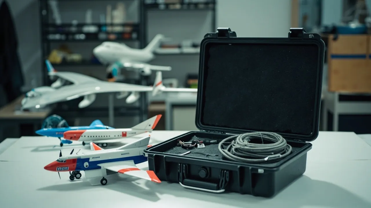
Protecting a scale model in transit means holding a precision structure of high slenderness, low strength and zero redundancy in an environment where it cannot move and cannot resonate. The control surfaces, propellers and landing gear of a model aircraft; the masts, rigging and railings of a ship model; the mirrors, wings and wheels of a model car all share the same traits: thin sections, long lever arms and almost no surplus strength. They are designed for aerodynamic or display loads, not for a squeeze, a resonance event or a free fall. So the engineering objective is not a vague "impact resistance" but three conditions holding at once: structural parts must never touch the case wall (zero displacement), fragile parts must carry no sustained load (zero preload), and the case interior must not exhibit low-frequency vibration matching the model's natural frequency (vibration isolation).
Scale models differ from general collectibles in one decisive way: after transport they usually have to work, not merely look correct. A model aircraft must fly again, which means hinge clearances, center of gravity and wing washout must be unchanged. A model car must retain steering and suspension travel. A ship model must keep its masts vertical and its rigging tensioned. That turns transport protection from "prevent breakage" into "preserve precision." This guide works through category risk, fragile-structure support, shape retention, vibration isolation, moisture and corrosion control, lithium battery compliance, test evidence and acceptance, with parameters and tables that can be written directly into a specification.
Table of Contents
- 1. Scale Model Categories and Their Transport Risk Profiles
- 2. Why Scale Models Are Especially Sensitive to Low-Frequency Vibration and Zero-Displacement Failure
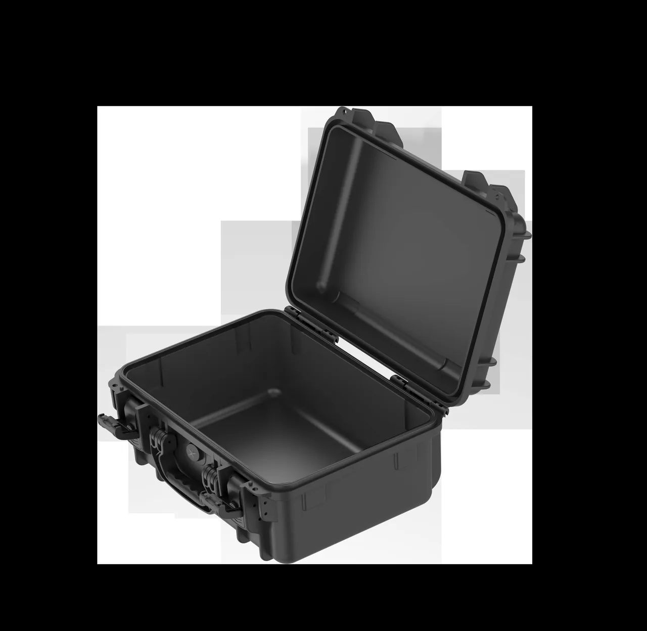
- 3. Ten Typical Damage Classes in Transit
- 4. Control Surfaces, Propellers and Landing Gear: Dedicated Support for Fragile Structures
- 5. Fuselage and Wing Shape Retention: Twist, Dihedral and Airfoil
- 6. Model Cars: Wheels, Mirrors, Wings and Paint
- 7. Ship Models: Masts, Rigging and Deck Detail
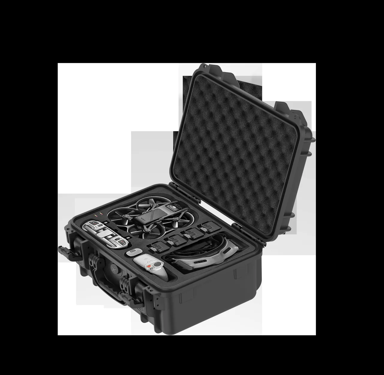
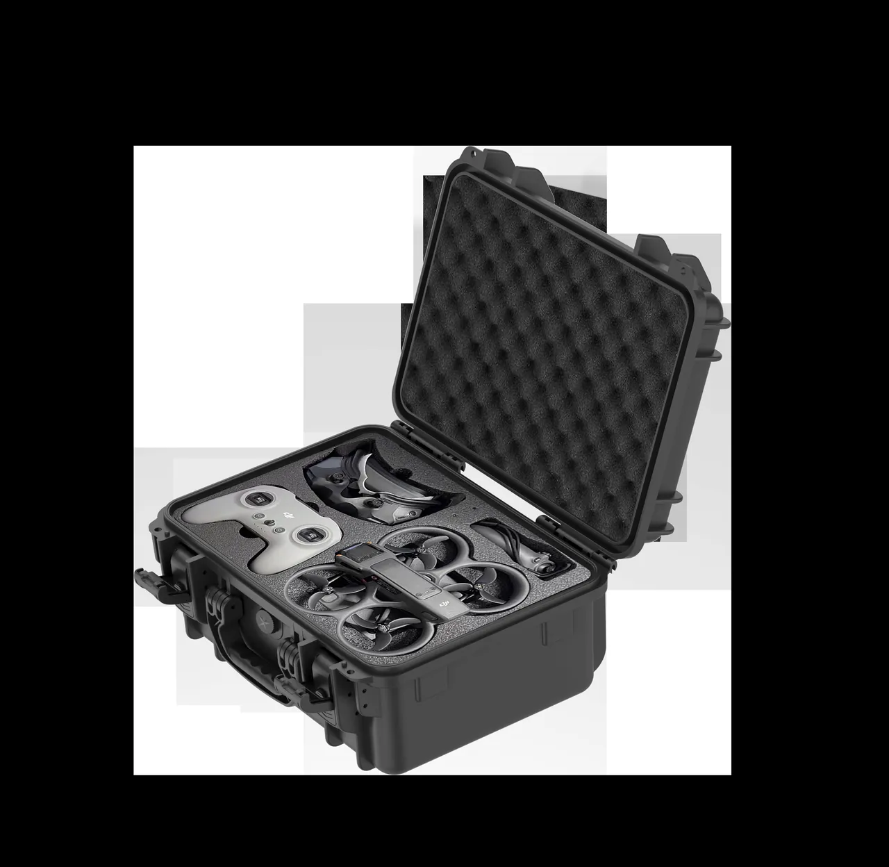
- 8. Insert Design: Split Cavities and Modular Cradles
- 9. Vibration Isolation: Spring-Mass Systems and Resonance Avoidance
- 10. Moisture Control, Corrosion Prevention and Metal Part Protection
- 11. Lithium Battery Compliance for Powered Models
- 12. Shell Materials and Structural Options
- 13. Ingress Protection and Environmental Test Evidence
- 14. Packing Density, Size Families and Multi-Model Transport
- 15. Trade Shows, Competitions and Club Turnaround
- 16. Customization Flow, Acceptance and Cost Structure
- Frequently Asked Questions
- Conclusion and Further Reading
1. Scale Model Categories and Their Transport Risk Profiles
The category spans an enormous range, from a few tens of grams of static plastic to a gasoline-powered model weighing over ten kilograms. Failure modes differ enough that specifications must be defined per category.
| Category | Typical size | Most fragile features | Primary risks | Protection priority |
|---|---|---|---|---|
| --- | --- | --- | --- | --- |
| Fixed-wing electric aircraft | Wingspan 600 to 3000 mm | Control surfaces, propeller, landing gear, vertical tail | Compression, resonance, control surface loading | Split support, positive location, isolation |
| Helicopter and multirotor | Rotor diameter 300 to 1500 mm | Blades, main shaft, gimbal, video antenna | Blade deformation, shaft bending | Blade clamps, suspended shaft |
| Model cars (static and RC) | Length 80 to 600 mm | Mirrors, rear wing, wheel hubs, paint | Point loads, relative friction | Full-wrap cavity, soft contact |
| Model ships (static and RC) | Length 300 to 2000 mm | Masts, rigging, railings, propeller | Bending, tangling, humidity | Longitudinal cradle, moisture control |
| Model railways | Length 100 to 400 mm | Pantographs, cowcatchers, bogies | Compression, derailed parts mixing | Compartmentalization, discrete slots |
| Resin and metal figure models | Height 150 to 800 mm | Protrusions, seams | Fracture, resonance fatigue | Full-wrap cavity, soft contact points |
The message from this table is simple: one case cannot serve every category. The correct sequence is to define the fragile-structure list per category, assign a support method and a restraint direction to each fragile structure, and only then select the shell.
2. Why Scale Models Are Especially Sensitive to Low-Frequency Vibration and Zero-Displacement Failure
Ordinary cargo fears drops. Scale models fear vibration, because of structural dynamics.
Slenderness drives low natural frequencies. The natural frequencies of model wings, control surfaces and ship masts typically fall in the tens of hertz range. Road transport energy, however, concentrates in the 2 to 20 Hz low-frequency band, and rail and full-container ocean freight also carry substantial low-frequency content. When excitation frequency approaches a structure's natural frequency, resonance amplifies displacement, often by a factor of several. The result: the package arrives undamaged, yet control surface hinges have loosened, the mast root has developed micro-cracks, and the wing carries invisible interlaminar damage.
Vibration fatigue accumulates. A single shipment may impose tens of thousands of small-amplitude cycles. For composite skins, thin-wall plastic parts and bonded joints, vibration fatigue damage accumulates and may not show after the first shipment at all — failure appears after the second or third. This explains a common experience in modeling circles: "shipping it this way was fine last time" is not luck, it is accumulated damage crossing a threshold.
Relative displacement is the real killer. Even with the case secured, internal moving parts — servo linkages, suspension, traversing turrets — reciprocate within their travel under vibration, producing wear and point impacts. Fixing the assembly therefore has to extend to locking internal moving parts.
An operational zero-displacement criterion. A workable definition: under a load of three times the model's own weight applied in any direction, relative displacement between model and case, and between models, should stay below 1 mm. This criterion can be used directly in prototype validation.
For the broader logic of impact-resistant and cushioning structures, see sealed and shock-resistant case structures.
3. Ten Typical Damage Classes in Transit
| Damage class | Typical manifestation | Primary cause | Countermeasure |
|---|---|---|---|
| --- | --- | --- | --- |
| Control surface fracture | Broken aileron, elevator or rudder corners | No support, point contact, pressed by adjacent items | Dedicated surface cradles, hard stops |
| Propeller deformation and cracking | Bent tips, cracked roots | Stacking, unsupported bending, resonance | Blade clamps, root support |
| Landing gear bending | Bent struts, misaligned wheels, retraction jams | Full model weight bearing on gear | Suspend gear, or carry load through the belly |
| Fuselage skin denting | Sidewall dents, wrinkled skins | Lateral compression, stacking load | Soft lateral stops, rigid walls |
| Wing twist and dihedral change | Asymmetric wings, tip height mismatch | Single-point support, stacking | Multi-point cradles, root-plus-tip support |
| Tail misalignment | Crooked vertical tail, loose horizontal tail | No support, free swinging | Vertical tail clamping, horizontal tail tray |
| Hinge loosening and clearance growth | Wobbly surfaces, out-of-tolerance gaps | Repeated vibration, reciprocating loads | Vibration isolation, surface locking |
| Paint transfer and decal lifting | Rubbed paint, lifted waterslide decals, uneven matte | Relative friction, plasticizer migration | Zero displacement, acid-free plasticizer-free barrier |
| Metal oxidation and corrosion | Dulled gear struts, rusted screws | High humidity, salt fog, hand sweat | Sealed moisture control, anti-corrosion paper, gloves |
| Loose accessory loss | Missing screws, linkages, antennas, propellers | No compartments, no manifest | Numbered compartments, in-case manifest |
Seven of these ten are structural damage, and structural damage is essentially irreversible. Correcting a twisted wing, a dented fuselage or a bent landing gear still leaves geometry that no longer matches the original, and flight quality depends directly on that geometry. Return on investment for a scale model case should therefore be measured against preventing a single structural failure.
4. Control Surfaces, Propellers and Landing Gear: Dedicated Support for Fragile Structures
These three zones break most often and deserve the largest share of design effort.
Support principles for control surfaces. A control surface connects to the fixed surface through hinges, has a long lever arm and low stiffness, and loads easily under vibration. Three support methods apply. Bridge cradles: a soft cradle runs parallel to the surface beneath it, constraining it from both sides without carrying its weight. Clamp stops: soft blocks grip the leading and trailing edges, limiting swing. Face support: a low-hardness foam pad inserted between moving and fixed surfaces absorbs the swing clearance. For model aircraft, add hinge locking — a soft block or tape that holds the surface at neutral so linkages and servos do not see reciprocating loads.
Propeller protection. Propeller risk comes from three sources: deformation under stacking, root bending and tips puncturing other parts inside the case. Measures include moulded blade clamps that hold blades at their original pitch and spacing, a support block at the root, clearance between blades to prevent rubbing, and disassembly into separate packaging where practical.
Landing gear handling. Landing gear is designed for ground support and touchdown shock, not for stacking. If the full model weight rests on the gear, struts bend, tires deform and retraction mechanisms jam. The correct approach is to carry the load through the fuselage or main spar and leave the gear suspended, with positive stops at the wheel wells or retraction points to prevent struts swinging in transit.
Vertical and horizontal tails. A vertical tail is typically tall and thin, making it the first casualty of lateral impact. Add soft clamping blocks on both sides and a buffer pad on the case lid directly above, forming a two-way restraint. Horizontal tails are best carried on a tray so they rest on a surface rather than spanning unsupported.
For cavity and cradle design parameters, see custom foam insert design flow and EVA foam insert custom process.
5. Fuselage and Wing Shape Retention: Twist, Dihedral and Airfoil
"Not broken" does not mean "not deformed." Wing twist distribution and dihedral directly determine flight behavior and are among the easiest parameters to damage in transit and the hardest to detect.
Sensitivity of twist and dihedral. Most designs build in negative twist at the tip to improve stall behavior, and dihedral for roll stability. These parameters often carry only one or two degrees of design margin. If a wing is supported at a single point in transit, or cinched by a strap at mid-span, the spar twists and bends, and the model arrives with one wingtip several millimeters higher than the other, producing a persistent roll tendency in flight. Such deformation is usually not fully recoverable, because the spar and skin have already seen plastic or damage-level strain.
Three shape-retention principles. First, two-point support at minimum: a wing should be supported at root and tip, with an intermediate point added if the span demands it, to avoid long unsupported spans. Second, area support over line support: cradle contact area should be as large as possible and curved to match the airfoil, avoiding line contact that creates local dents. Third, independent left and right cavities: wings should sit in their own cavities so they cannot interfere with each other, and a single side can be replaced if damaged.
Fuselage sections. A long fuselage supported only at both ends bends under its own weight plus vibration. Add a third support near the center of gravity for a three-point arrangement. Where wings are removable, disassembled transport is often safer than shipping assembled — but every subassembly must have its own cavity, otherwise disassembly increases risk rather than reducing it.
Clear parts and canopies. Canopies, windshields and camera domes are thin-walled transparent parts with weak point-load resistance. They must not touch hard parts directly and should be covered with an acid-free protective film. Electronic bays also need static protection; see ESD shielding case design.
6. Model Cars: Wheels, Mirrors, Wings and Paint
Model cars are small but extremely detail-dense, making them the category with the highest risk per unit volume.
Wheels and suspension. Static model wheels usually rotate freely, and RC cars add suspension travel. If the full vehicle weight rests on the wheels in transit, tires deform, hubs crack and suspension bottoms out. The correct approach is to carry the load through the chassis or base plate, leaving wheels suspended or only lightly touching, with travel-limiting blocks inside the suspension range to stop reciprocation under vibration.
Mirrors and rear wings. These are archetypal "breaks on first contact" parts. Mirror stalks are thin and outboard; wing mounts have long lever arms. Provide dedicated relief cavities so the mirror sits in a void rather than against foam, and add an upper stop for the rear wing so the lid does not press on it. Under no circumstances should the vehicle be fixed by simply compressing it in place.
Paint protection. Model car paint is typically multi-layer with clear coat and is most vulnerable to relative friction and plasticizer migration. Contact layers should be acid-free and plasticizer-free, and the model must be fully immobilized with no permitted relative motion. Freshly painted parts that have not fully cured should be allowed additional cure time before packing.
Clear parts and small components. Lens covers, windows, wipers and antennas should sit in their own compartments. Numbered slots for each small part type allow placement by number, preventing both loss and miscounting.
7. Ship Models: Masts, Rigging and Deck Detail
Ship models contain the most slender structures of any scale category and often mix wood, paper and metal, so the protection logic differs from aircraft and cars.
Masts and rigging. Masts are slender with long lever arms, while rigging is a flexible connection. Together they form a low-stiffness, high-redundancy structure that looks compliant but cannot be restored once tangled or loaded. Measures: a longitudinal cradle that supports the mast along its axis rather than gripping it at a single point; rigging wrapped in acid-free tissue and fixed in a dedicated station; and no free-hanging rigging under any circumstances. Where detachable, shipping masts separately is preferable.
Why longitudinal support matters. A ship model is typically several times longer than it is tall. If a transverse cavity supports it only at midship, bow and stern span unsupported and bend. The correct approach is continuous or three-point-plus longitudinal support along the keel, so the hull lies on the cradle along its length.
Humidity and wood construction. Wooden hulls and paper detail are humidity sensitive. Relative humidity above 65% causes wood to swell, coatings to blister and paper to distort; below 40% risks desiccation cracking. Hold in-case relative humidity between 45% and 55% and provide a desiccant bay. Models with metal fittings also need oxidation protection, which vapor-phase corrosion inhibitor paper provides. For moisture control configuration, see pressure equalization valve design.
Preventing deck detail crushing. Railings, turrets, cranes and miniature lifeboats project above the main deck line and are easily crushed when the lid compresses. Every protrusion needs reserved clearance, and the lid interior should carry a relief recess at each corresponding position rather than a compression pad.
8. Insert Design: Split Cavities and Modular Cradles
The most effective insert architecture for scale models is split cavities plus modular cradles.
Split cavity. The model is broken into modules — fuselage section, left and right wings, tail group, landing gear, accessory box — and each module gets its own cavity. Each module then receives its optimal support direction, and a single damaged module can be re-foamed without remaking the whole insert. The trade-off is greater space consumption and a manifest requirement.
Modular cradle. Cradles are designed around the support point positions of a model family and can be reused across types. A family of aircraft with different wingspans, for example, can share root cradles and add tip extensions. This significantly reduces tooling and machining cost.
Zoning and removable dividers. When a case must carry batteries, a transmitter, tools and spare propellers alongside the model, a removable divider system lets the zoning adapt to configuration. See case removable divider system.
Material selection. Use EVA for load-bearing layers for its resilience, dimensional stability and machining accuracy; acid-free foam or soft fabric at contact surfaces; and high-density PE or rigid backing plates to spread load at heavily loaded points. For material comparisons, see case foam material comparison.
| Insert scheme | Suitable categories | Packing density | Unit protection | Reusability | Cost |
|---|---|---|---|---|---|
| --- | --- | --- | --- | --- | --- |
| Split cavity | Aircraft, ships, large figures | 30% to 50% | Very strong | Low (model-specific) | High |
| Modular cradle | Multiple types in one family | 40% to 60% | Strong | High (cross-type) | Medium |
| Full-wrap cavity | Model cars, small and mid models | 45% to 65% | Strong | Low | Medium |
| Compartment tray | Model railways, small accessories | 60% to 75% | Medium | High | Low |
9. Vibration Isolation: Spring-Mass Systems and Resonance Avoidance
Vibration isolation is the largest technical difference between a scale model case and a general protective case, and the most frequently overlooked element.
Basic principle. The goal is to keep the natural frequency of the case-support-model system well away from the excitation frequency. Ideally the system natural frequency should sit below roughly 1 over the square root of 2 times the lowest excitation frequency to enter the isolation region. Road transport concentrates energy between 2 and 20 Hz, so a target natural frequency below about 3 to 5 Hz would be ideal — but that is extremely difficult for a small case, because frequency rises with stiffness and falls with mass.
Three practical paths.
- Reduce support stiffness by replacing high-hardness foam with low-hardness, low-resilience foam or an elastic suspension membrane. The cost is that static displacement must be constrained, or the model will sink.
- Add constrained damping by inserting damping layers, such as high-damping adhesive films or composite structures, between support layers to clip the resonance peak. This is the most practical path because it does not sacrifice static support capacity.
- Avoid resonance by pushing the natural frequency high, for example above 40 Hz, when it cannot be pulled into the isolation region, so excitation energy cannot effectively drive it. This path works by increasing support stiffness.
A workable validation method. Load the case on a vibration table using a GB/T 4857 or ISTA vibration program, attach accelerometers to key model locations such as control surfaces, wingtips and mast tops, and record the transmissibility curve. If transmissibility significantly exceeds 1 in any band, resonance amplification is present and support stiffness or damping must change. Without test capability, at minimum run drop and sweep pre-tests and inspect key locations for new cracks. See ISTA transport testing procedure selection and ASTM D4169 distribution cycle testing.
The "softer is safer" misconception. A common packing habit is to fill the case with soft foam on the assumption that softer is safer. In practice, overly soft support causes static settling and lateral instability: the model slowly sinks and tilts inside the case until it contacts a wall, creating a new load path. The correct approach is graded stiffness — a load-bearing layer stiff enough to limit displacement, a soft contact layer to protect surfaces, and a damping layer in between to clip resonance peaks.
10. Moisture Control, Corrosion Prevention and Metal Part Protection
Scale models frequently combine metals such as aluminum struts, stainless screws, brass fittings and die-cast alloys with wood, paper and composites, so humidity control must satisfy several materials at once.
Humidity window. Hold in-case relative humidity between 45% and 55%. Above 65% drives wood swelling, paper distortion, metal corrosion and mold; below 40% risks wood cracking and adhesive failure.
Metal part corrosion. Aluminum landing gear, steel linkages and brass fittings oxidize and discolor in humid environments. Measures: wrap metal parts in vapor-phase corrosion inhibitor (VCI) paper; avoid bare-hand contact with metal surfaces, since hand sweat carries salts; include desiccant in the case; and raise sealing to IP67 for ocean freight lanes.
Composites and bonded joints. Composite skins and bonded joints are sensitive to both moisture and vibration. Moisture ingress reduces interlaminar strength while vibration accelerates delamination. Control humidity and isolate vibration together, and add support at critical joints to reduce bending loads.
Temperature and condensation. Across climate zones, day-night temperature swings cause condensation on inner walls. Add a pressure equalization valve that passes air but not water to avoid differential-pressure damage to seals, and avoid packing in hot, humid conditions.
11. Lithium Battery Compliance for Powered Models
Electric aircraft, cars and boats typically carry lithium polymer batteries. These are dangerous goods, so compliance is a precondition rather than a recommendation.
Key compliance points (confirm against the actual transport mode and destination regulations).
| Transport mode | Primary framework | Key requirements | Common obstacles |
|---|---|---|---|
| --- | --- | --- | --- |
| Air (passenger and cargo) | Lithium battery provisions of the international air transport rules | State-of-charge limits, watt-hour limits, packing and marking | Over-limit watt-hours without approval, missing marks |
| Road | UN Model Regulations on dangerous goods and regional or national transpositions | Classification, packaging, marking, documentation | Misclassification, missing documents |
| Sea | International Maritime Dangerous Goods Code | Packaging, marking, segregation | Non-compliant packaging, incomplete documents |
| Parcel | Carrier-specific lithium battery policies | Stricter quantity and watt-hour limits | Outright refusal |
Engineering support points. First, batteries should be removable and stored in their own compartment, isolated from the model so battery damage cannot propagate into a thermal event affecting the model. Second, battery compartments should consider thermal isolation and venting and must not be fully sealed without ventilation. Third, terminals must be insulated with original caps or insulating sleeves. Fourth, the case exterior should reserve a clear dangerous goods marking area for regulatory labels. Fifth, a fixed document pocket for instructions, test reports and declarations prevents loss in transit.
For general dangerous goods packaging requirements, see ADR and IMDG hazmat transport case requirements. Note that compliance determinations must follow current regulations and carrier policies and should rely on the opinion of a qualified body; this article is not a compliance conclusion.
12. Shell Materials and Structural Options
| Option | Construction | Strengths | Limitations | Suitable categories |
|---|---|---|---|---|
| --- | --- | --- | --- | --- |
| Injection-moulded ABS case | One-piece lid and base with gasket, hinges and latches | Good stiffness, high sealing, reusable | Tooling investment, heavier unit | Mid and large aircraft, ships |
| PP twin-wall case | Twin-wall sheet, edge trim, plastic latches | Light, inexpensive, collapsible | Moderate stiffness, low sealing | Model cars, railways, short haul |
| PC case | Polycarbonate sheet | Highest impact resistance, visible contents | Higher cost, scratch-prone | High-value single items, display turnaround |
| EVA composite case | EVA shell with integrated insert | Light, good cushioning | Weak puncture resistance | Small and mid models, club turnaround |
| Aluminum-frame flight case | Aluminum frame, panels, hard insert | Very high strength and stiffness | Heavy, costly | Competitions, touring, intercontinental freight |
Selection criteria. Model weight and size first — above roughly 8 kg or a wingspan beyond about 1.5 m, prefer ABS or aluminum frame. Then turnover count, where club and competition round trips justify a structure with replaceable parts. Then transport mode, since air freight requires pressure equalization and a dangerous goods marking area. Finally, visibility, where trade shows favor a PC window with UV blocking. For sheet and structural fundamentals, see plastic protective box selection and structure.
13. Ingress Protection and Environmental Test Evidence
Ingress protection ratings follow IEC 60529 and its national equivalents such as GB/T 4208. For scale models the primary threats are dust and moisture, not immersion.
| Rating | Meaning | Value for scale models | Recommended scenarios |
|---|---|---|---|
| --- | --- | --- | --- |
| IP54 | Dust protected plus splash resistant | Basic dust control | Club internal, indoor turnaround |
| IP65 | Dust tight plus water jet resistant | The workhorse rating | Parcel, LTL, trade shows |
| IP67 | Dust tight plus short-term immersion | Ocean freight and severe weather | Full-container ocean, high-rainfall regions |
| IP68 | Dust tight plus continuous immersion | Specialized lanes | Requires stated test conditions |
Test reference combinations.
| Reference | Primary use | Relevance to scale models |
|---|---|---|
| --- | --- | --- |
| GB/T 4857 series | Stacking, vibration, impact, drop | Establishes strength and stacking limits |
| ISTA 1/2/3 series | Transport package performance procedures | Combines test intensity by lane |
| ASTM D4169 | Distribution cycle performance testing | Simulates a complete distribution cycle |
| MIL-STD-810H | Environmental test methods | Used as a method reference only; not a military certification |
| IEC 60529 / GB/T 4208 | Enclosure ingress protection | Defines and verifies IP rating |
| UL94 | Flammability classification for plastics | Flammability requirement for inserts and windows |
The MIL-STD-810H clarification bears repeating: it is a test method standard, and testing by its methods confers no military certification or approved-status designation. Marketing and documentation must strictly separate the two. For scale model cases, its practical value is providing a reproducible vibration, shock and temperature-humidity procedure, which is especially useful for validating a vibration isolation scheme.
In practice, JUNZHJIA combines test items according to the customer's model list and lane: club and competition lanes center on ISTA series and drop testing, full-container ocean lanes add high-temperature high-humidity exposure and long-duration stacking, and battery-equipped configurations receive coordinated dangerous goods packaging design. See transport packaging basic tests and strength design and MIL-STD-810H environmental testing application.
14. Packing Density, Size Families and Multi-Model Transport
Packing density. Split cavity schemes typically reach 30% to 50%; modular cradle schemes 40% to 60%; compartment trays for model railways and accessories 60% to 75%. A scheme below 25% indicates a mismatch in cavity design or size family.
Size families. Establish four to six fixed outer sizes covering mainstream wingspans and hull lengths, for example by internal length bands of 400, 600, 900 and 1200 mm. One shell then serves multiple model types, with only the insert module changing.
Unit weight and handling. Keep single-person frequent handling below about 15 kg and two-person or cart-assisted handling below about 30 kg. Large ship models and multi-model cases should have casters and a telescopic handle; see case wheels and trolley handle configuration and portable transport case structure.
Layout principles for multi-model transport. First, align all models in the same direction so noses do not load tails. Second, avoid stacking: stand models upright where possible; where stacking is unavoidable, place the heavier item stably, put lighter items above, and insert rigid dividers so the load passes through the divider rather than the model below. Third, centralize accessories: batteries, transmitter, tools and spare propellers go into their own zone so they cannot move freely and strike models, which is the most common damage source in multi-model transport. Fourth, number everything: one slot per model, one number per slot, with packing and counting done by number and a manifest in the case.
15. Trade Shows, Competitions and Club Turnaround
Competitions and club round trips. Characteristics are high-frequency opening, many tools and spares on site, and time pressure. Priorities: a lid that holds position for one-handed access; insert zoning matching assembly order; a fixed, visible accessory zone for propellers, linkages, screws and tape; case numbering matched to model type; and IP65 with reinforced corners. Where a club shares cases, standardizing one shell type and insert specification enables interchange and consolidated shipping.
Trade show display. Characteristics are prolonged exposure to a public environment, a need for dust and bump protection, and repeated handling. Priorities: a PC or PMMA window with UV blocking, since prolonged exposure degrades paint and clear parts; branding and model identification on the case exterior; and two defined positions inside — a display position and a transport position — so supports do not have to be re-tuned at every move.
Long-term storage. Where models are stored in cases long term, keep in-case RH between 45% and 55%, avoid direct sunlight with illuminance held below roughly 200 lux as an experience guideline, and inspect every three to six months: whether control surfaces remain at neutral, whether suspension stops are still in place, whether any metal part shows oxidation, and whether desiccant needs replacing.
16. Customization Flow, Acceptance and Cost Structure
Customization flow (six steps).
- Model list and fragile structure definition: list types, dimensions, weights, fragile structures and their allowable loads.
- Support scheme design: assign a support method, restraint direction and contact material to each fragile structure.
- Insert and shell prototyping: build cavity and cradle prototypes and validate the zero-displacement criterion on real models (relative displacement below 1 mm under three times own weight).
- Test validation: select vibration, drop, stacking and sealing tests by lane, with transmissibility testing where required.
- Acceptance freeze: appearance, dimensions, assembly, sealing, accessory completeness and documentation.
- Production and delivery: manufacture to batch with inspection records and material documentation.
Cost structure.
| Cost item | Nature | Drivers | Optimization direction |
|---|---|---|---|
| --- | --- | --- | --- |
| Shell tooling | One-time | Size, structure, surface finish | Reuse size families |
| Insert machining and forming | Semi-one-time | Cavity count and complexity | Modular cradles reused across types |
| Shell material | Recurring | Material type, thickness, flammability | Choose by lane |
| Seals and hardware | Recurring | Gasket material, latch grade | Standardize wear parts |
| Testing and documentation | Per batch | Item count, laboratory accreditation | Combine the minimum necessary items |
| Assembly labor | Recurring | Compartment count, manifest complexity | Numbering and poka-yoke design |
Acceptance points. Build acceptance at three levels: appearance and dimensions including tolerances; function covering opening, sealing, latching and pressure equalization; and packing and documentation covering manifest, numbering, seals and material certificates. Sampling plans can follow AQL methods; see custom case acceptance and AQL sampling. For supplier selection, see how to choose a protective case OEM factory, and for tooling economics, custom case mold cost analysis.
Frequently Asked Questions
Q: Why did my model aircraft survive shipping last time but break this time?
A: This is classic accumulated vibration fatigue. Model wings, control surfaces and masts are low-stiffness, high-slenderness structures whose natural frequencies often land in the tens of hertz range, overlapping heavily with the 2 to 20 Hz low-frequency energy of road transport, which makes resonance amplification likely. A single shipment can impose tens of thousands of small cycles, and composite skins, thin-wall plastic parts and bonded joints accumulate damage under those cycles. Failure may not appear after the first or second shipment and then occur suddenly on the third, so a prior success is not evidence of future safety. The practical response is to upgrade protection from impact resistance to vibration resistance: lock internal moving parts such as control surfaces and suspension travel, add a damping layer in the support stack to clip resonance peaks, and validate with a GB/T 4857 or ISTA vibration program. Where vibration testing is unavailable, at minimum re-measure key clearances and geometry after each shipment and keep a trend record. A simple log of hinge clearance and wingtip height difference is one of the cheapest diagnostic tools available, because a rising trend shows up long before a visible failure does.
Q: Is softer foam packed more densely always safer?
A: No, and this is the most common misconception. Overly soft support causes two problems. First, static settling: the model sinks continuously under its own weight until it contacts a case wall, creating a new load path. Second, lateral instability: under low-frequency vibration the model gradually tilts and shifts, changing from being held to being braced against a wall. The correct approach is graded stiffness: a load-bearing layer of EVA or high-density material stiff enough to limit displacement, a soft contact layer of acid-free foam or fabric to protect surfaces, and an optional damping layer between them to clip resonance peaks. Validate against one clear criterion: under a load of three times own weight in any direction, relative displacement between model and case must stay below 1 mm. Only then is it genuinely fixed. A useful bench check is to press the packed case from each side and confirm the model does not visibly move relative to its cavity; if it shifts, the support is too soft regardless of how much foam is inside the case.
Q: Should a model aircraft be shipped assembled or disassembled?
A: It depends on the detachable design and the insert's capability. Disassembled transport gives each large part its optimal support direction and avoids long unsupported spans, but it increases part count, and without dedicated cavities the parts are more likely to strike each other. The test is this: if the assembled model fits one case with support at root, mid-span and tip, assembled transport is usually simpler and introduces less assembly error. If the span is large or the fuselage slender enough that support would be single-point or suspended, disassembly is safer. Whichever route you choose, moving parts must be locked — control surfaces at neutral, landing gear suspended or positively stopped, suspension blocked — otherwise vibration keeps loading the structure from the inside. One practical compromise is to ship the airframe assembled while the wings and tail group remain removable, so the fuselage gets a three-point cradle while the large surfaces get their own cavities and their own optimal support directions. That combination usually delivers the most protection per unit of case volume.
Q: Does the IP rating really matter for scale models?
A: For scale models the main threats are dust and moisture, not immersion, so IP65 covers about 95% of scenarios: dust tightness keeps particles out of servos, bearings and ESCs, while water jet resistance handles rain during handling and case washdown. Only three lane types justify IP67: full-container ocean freight with prolonged high humidity and condensation, open-air handling in high-rainfall regions, and lanes where immersion is genuinely possible. Note the side effects of over-specifying: higher ratings mean greater gasket compression, more opening resistance and a stronger case for pressure equalization, and operators are more likely to damage contents through excessive force when opening. Also remember that an IP rating is a system-level outcome — gasket material, groove geometry, latch clamping force and shell stiffness must all match. Require verification records against IEC 60529 or GB/T 4208 at purchase. Consider also labelling the case with its rating and the date of the last seal inspection, because a case that has been opened and reclosed hundreds of times without inspection can deliver noticeably lower protection than its label suggests.
Q: Can models with lithium batteries ship as ordinary parcels?
A: Not in general; the answer depends on watt-hours, quantity, packaging and carrier policy. Broadly, air transport imposes explicit limits on state of charge, watt-hours and packing marks; sea transport falls under the International Maritime Dangerous Goods Code; road transport follows the UN Model Regulations and regional or national transpositions; and parcel carriers apply stricter in-house policies that often refuse over-limit batteries outright. Engineering support points are: make the battery removable and store it in its own compartment isolated from the model; provide thermal isolation and venting in the battery compartment rather than fully sealing it; insulate terminals; reserve a dangerous goods marking area on the case exterior; and provide a fixed document pocket. Compliance determinations must follow current regulations and carrier policy and should rely on a qualified body's opinion; this article is not a compliance conclusion. Keep a printed copy of the carrier's current lithium battery policy with the shipping documents as well, because carrier rules change more often than the underlying regulations and a configuration accepted this quarter may be refused the next.
Q: Why is a ship model harder to protect than a model car?
A: Three difficulties compound. First, many slender structures: masts, rigging, railings and cranes are all low-stiffness, long-lever-arm features with high resonance risk, and rigging cannot be fully restored once tangled. Second, mixed materials: wood, paper, metal and composites coexist, and their optimal humidity windows do not fully coincide, so in-case RH must be held in the 45% to 55% overlap while oxidation protection is handled separately with vapor-phase corrosion inhibitor paper. Third, a different support direction: a hull needs continuous or three-point longitudinal support along the keel, and a transverse cavity lets bow and stern span unsupported and bend. A ship model case therefore combines a longitudinal cradle, axial mast support and relief recesses for deck protrusions, rather than the full-wrap cavity used for cars. When in doubt, prioritise longitudinal support and moisture control first, since those two account for most ship model failures, and refine mast and rigging support once the hull carries load correctly along its length.
Q: How should a vibration isolation scheme be validated?
A: In three layers. The first is static validation: check the zero-displacement criterion, requiring relative displacement below 1 mm between model and case under three times own weight in any direction, with all moving parts locked. The second is swept-sine validation: mount the case on a vibration table, load it with a GB/T 4857 or ISTA vibration program, attach accelerometers at key model locations such as control surfaces, wingtips and mast tops, and record transmissibility; if transmissibility significantly exceeds 1 in any band, resonance amplification is present and support stiffness or damping must change. The third is lane validation: run the complete test set for the real lane including drop and stacking, then re-measure key geometry after unpacking, such as wingtip height difference, dihedral and control surface clearance. Without vibration test capability, at minimum run drop testing with re-measurement and keep post-shipment records so trends can drive design changes. Record the results in a per-case log with the date, the lane and the measured values, so any drift across successive shipments becomes visible before it becomes a failure.
Q: When several models share one case, what is the safest layout?
A: Four principles. First, align all models in the same direction so noses do not create point loads on tails. Second, avoid stacking: stand models upright where possible; where stacking is unavoidable, place the heavier item stably, put lighter items above and insert rigid dividers so the load passes through the divider rather than the model below. Third, centralize accessories: batteries, transmitter, tools and spare propellers go into their own zone so they cannot move freely and strike models, which is the single most common damage source in multi-model transport. Fourth, number everything: one slot per model, one number per slot, with packing and counting done by number and a manifest in the case. Adding damping layers between levels and along the inner walls is also advisable, because a heavier multi-model case has a lower natural frequency and is more easily excited by low-frequency road input. Add a manifest sticker inside the lid showing which model sits in which position, so a case repacked away from the workshop still ends up with the same layout.
Q: How does a scale model case differ from an ordinary collectible case such as a figure case?
A: Three core differences. First, the protection goal differs: a figure case targets condition preservation with compression, moisture and light control, while a scale model case targets precision preservation and continued function, so airfoil twist, dihedral, hinge clearance and suspension travel must all survive intact. Second, the mechanical emphasis differs: figure cases mainly resist stacking and impact, whereas scale model cases must add low-frequency vibration isolation, because the natural frequencies of slender structures sit right in the main band of transport excitation. Third, the structural form differs: figure cases commonly use full-wrap cavities, while scale model cases more often use split cavities or modular cradles so each fragile structure gets its own support direction. Plenty of technology is shared — the zero-displacement criterion, 45% to 55% RH control, acid-free contact layers, IP65 versus IP67 selection, and hinge, seal and lock selection all apply to both. That is why both project types sit under the same methodology. As a general rule, the more of those four essentials a design already satisfies, the fewer cost compromises you have to make later, because the expensive failures are almost always the ones that were designed out first.
Conclusion and Further Reading
Protecting scale models in transport means treating structural precision as an acceptance object equal in importance to cosmetic integrity. The essentials compress into four statements: every fragile structure needs dedicated support (control surface cradles, blade clamps, suspended landing gear, axial mast support); every moving part must be locked (surfaces at neutral, suspension limited, linkages fixed); resonance must not occur inside the case (graded stiffness, damping layers, transmissibility validation); and the environment must be stable (45% to 55% RH, acid-free contact layers, corrosion prevention, IP67 where justified). Add manifest numbering and a dangerous goods marking area, and "ready to fly, drive or display on arrival" becomes a specification rather than an expectation.
The recommended sequence is: define the support scheme from the model list and fragile structure inventory, validate it with the zero-displacement criterion (relative displacement below 1 mm under three times own weight) plus vibration testing, then freeze acceptance with AQL sampling. JUNZHJIA can supply split-cavity and modular cradle designs by model list, vibration isolation and damping configuration, matched sealing components and reserved dangerous goods marking areas, and can route third-party testing and batch inspection documentation according to the customer lane, supporting wholesale, distribution and OEM/ODM supply.
Further Reading