

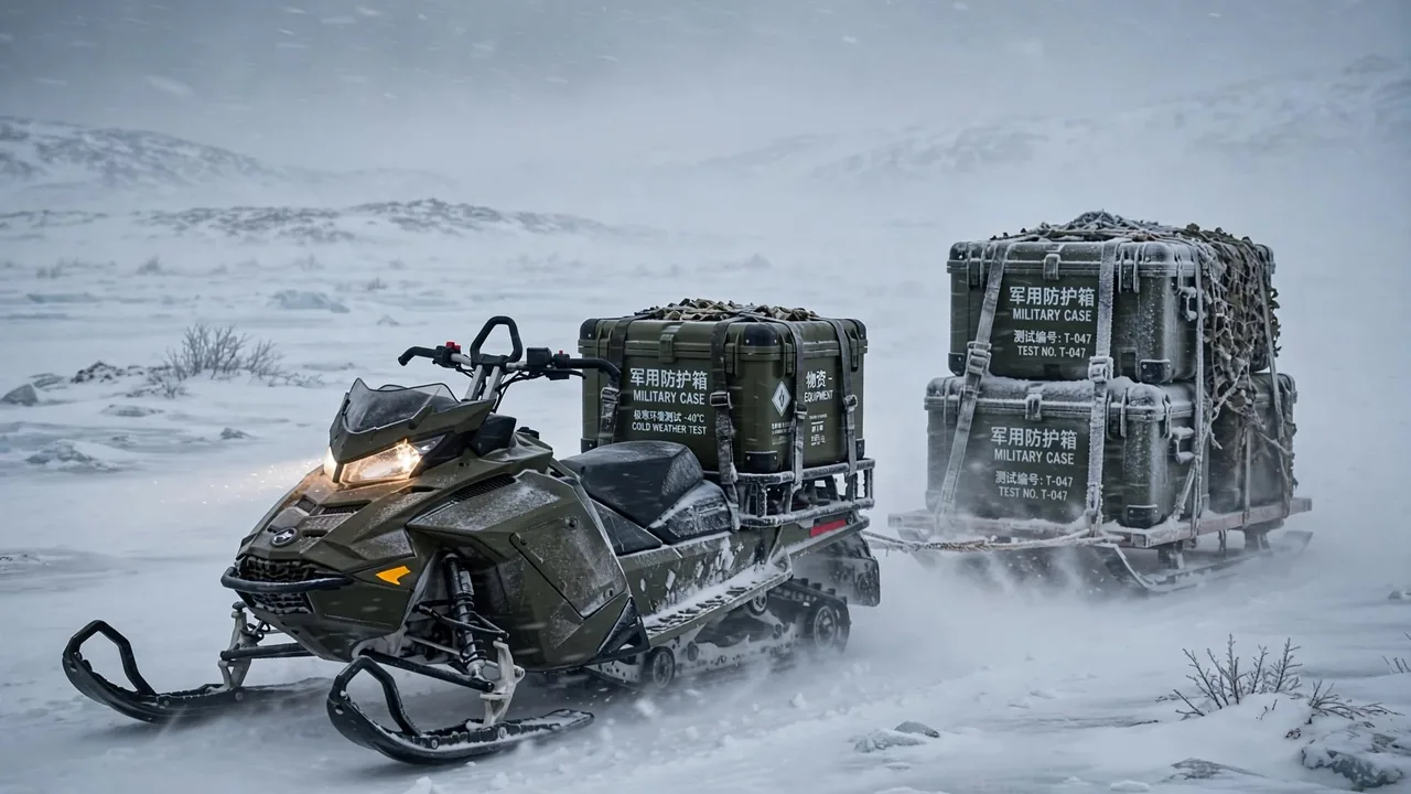
A power supply case is a specialized protective container built for field power equipment, portable power stations, distribution modules, and uninterruptible power supply components. Beyond the shock, vibration, dust, and water protection expected of a general equipment case, it must solve problems unique to electrical supply gear: many cables, mixed connectors, heavy modules, and concentrated heat. A qualified power supply case combines shell strength, internal cable routing, module fixation, thermal ventilation, and sealed protection into one coordinated system, and it can integrate with equipment cases, communication cases, and spare parts cases into a standardized field power support unit.
Definition and Scope of the Power Supply Case
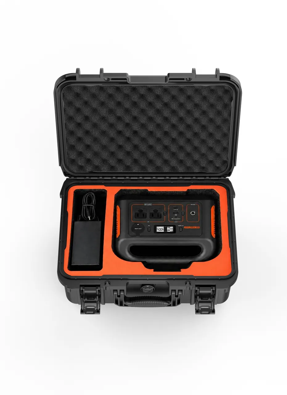
From a container engineering standpoint, a power supply case is a protective case whose purpose is to carry, protect, and organize power-related equipment. What sets it apart from a plain storage box is that its interior is deliberately divided into an equipment bay, a cable bay, and an accessory bay, with provisions for cable pass-through holes, grounding markings, and ventilation openings. Typical payloads include inverters, switched-mode power supplies, distribution modules, battery packs, charging power modules, and the adapters or measuring instruments needed for field work. For missions that must deliver electricity far from grid power, the power supply case often works alongside a protective case for outdoor power stations, where the former supplies a stable enclosure and environment control while the latter handles energy output and dispatch.
On the boundary of applicability, a power supply case always discusses the container level, that is, the shell and the internal layout, and never the circuit design, electrical parameters, or operating principles of the loaded equipment. Users must still confirm, based on local regulations, electrical codes, and transport requirements, whether a specific device may enter the case, how it should be wired, and whether extra isolation is needed. Keeping this boundary clear prevents treating the case supplier as an electrical solution provider and keeps both responsibility and technical discussion focused on structural protection.
Typical Risks for Field Power Equipment
Field power equipment faces more complex risks than indoor equipment. The first is mechanical risk: bumps, drops, and stacked loads during transport can shift heavy power modules, deform the shell, or loosen internal connections. The second is environmental risk: sand and dust infiltrate connectors and cause poor contact, rain and moisture degrade insulation, and day-night temperature swings create condensation inside the case. The third is maintenance risk: cables that are not secured will rub against each other or pull on connectors under vibration, and ventilation openings blocked by debris or stacking will let local temperature climb quickly.
Understanding these risks lets protection design hit the right points. For mechanical risk, reinforce the reinforcement ribs of the case and the stacking corners; for environmental risk, rely on seal strips and reasonable ventilation filtration; for maintenance risk, invest detail in cable trays and fixation structures. Listing the risk inventory clearly is the starting point for all subsequent selection and acceptance work, and it is also the most basic guarantee of field safety.
Shell Material and Structural Selection
The shell material of a power supply case is usually weighed between engineering plastics and aluminum alloy. ABS, PP, and PC engineering plastics are light, freely formed, and well insulated, suiting most field power scenarios; the trade-off described in the difference between PP, ABS, and PC cases directly determines how the shell behaves between low-temperature brittleness and high-temperature creep. Aluminum alloy shells offer higher stiffness, stronger impact resistance, and some electromagnetic shielding potential, fitting occasions that demand both vibration resistance and shielding. Regardless of material, attention should go to the weatherability grade and long-term aging of common plastic materials for protective cases.
Structurally, a power supply case needs more attention to wall thickness and rib coordination than an ordinary case. Heavier power modules mean the box bottom and side walls bear larger concentrated loads, and walls that are too thin will creep or even crack under long-term stacking. The reasonable approach is to determine critical thickness based on the relationship between wall thickness and strength, then use ribs to spread stress across the whole structure. For field cases that open and are carried frequently, the connection strength of hinges, latches, and handles also belongs to structural selection and must be considered together.
Internal Cable Routing and Tray Design
The most overlooked yet most usability-defining part of a power supply case is the internal wiring. Cables left unmanaged tangle into a ball inside the case, multiplying failure points and turning every repair into untangling. A proper power supply case pre-installs cable trays, tie points, and pass-through holes in the lining or frame, routes strong current, weak current, and signal lines in separate zones, and distinguishes them by color or label. Good tray design also keeps cables stationary when modules are removed, so only the device is replaced, shortening the time to restore field power.
The edges of trays and pass-through holes must be deburred and rounded to prevent cutting the cable jacket. For cables that must exit the case, a compressible sealed cable gland should be fitted, fixing the cable while maintaining the protection rating. Borrowing the zoning logic from equipment case and gear case layout, managing power, control, and accessory bays separately lets a power supply case keep clear electrical order even in complex tasks and reduces the probability of misoperation.
Fixation and Shock Isolation of Power Modules
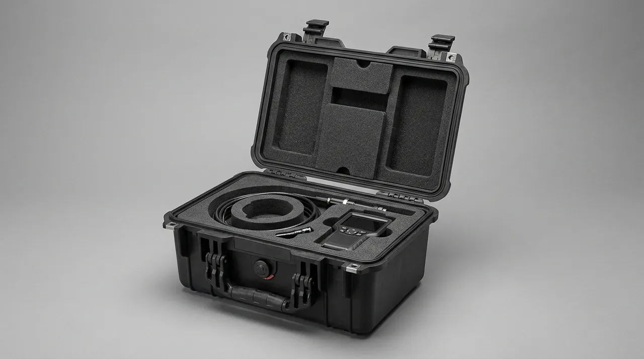
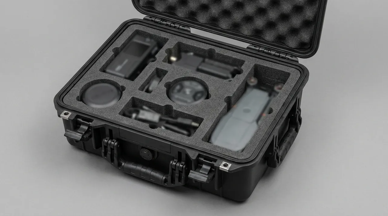
Power modules are often small in volume but high in density, with a concentrated center of gravity, making them movable heavy objects during transport. Therefore fixation is the first priority: the module bottom should be constrained by limit blocks, straps, or quick-lock pressure bars so it does not shift noticeably in any orientation. The fixation itself must not damage the device shell and must not block heat dissipation openings. Shock isolation relies on foam lining for cases to convert the rigid contact between module and case into flexible contact, absorbing impact energy from road conditions and drops.
Fixation and isolation must be designed together. Fixation without cushioning lets impact pass directly through the hard connection into the module; cushioning without fixation lets the module rattle inside the foam and hit the wall. A mature approach is limit plus cushion: use a harder limit structure to control the displacement range, and a softer foam to absorb the remaining impact. For power cases with multiple modules side by side, mutual isolation between modules should also be considered to avoid one loosening and colliding with the neighbor, creating chain damage.
Thermal Ventilation Structure Design
Power equipment generates heat when working, and a closed case lets heat accumulate. Cooling a power supply case must balance ventilation against protection. The passive option is to open dust-proof and water-proof ventilation windows on the case, relying on natural convection to carry heat away; the active option introduces small fans, air ducts, or heat-conductive pads to direct heat outside. Either way, the ventilation path should avoid direct rain direction and be fitted with filtration or louver structures to reduce dust ingress.
Special attention is needed because ventilation openings weaken sealing integrity. The inlets and outlets should be placed on the side or bottom leeward of the case, and the seal strip of the case should maintain overall protection elsewhere. For modules with particularly concentrated heat, a heat-conductive frame between the module and the wall can spread heat evenly. If the mission environment is extremely sensitive to temperature, the ideas in temperature-controlled case thermal stability can be referenced to add passive insulation or active temperature control at the container level.
Sealing Protection and Dustproofing
Power supply cases are often used in open and muddy environments, so sealing is a baseline requirement. The core of sealing is a continuous, compressed, aging-resistant seal strip and a flat, well-matched case lid surface. Reaching the level of an IP67 protective case means the case can be briefly immersed without water ingress, which is critical for sudden heavy rain or wading transport. But a high protection rating often comes with tighter sealing that may hinder heat dissipation, so sealing and ventilation must be coordinated as described above.
For dust prevention, besides the main seal strip, all cable glands, ventilation windows, and connector covers should be dust-proof, with filter cotton added where necessary. For power cases used long-term in salt spray or strong ultraviolet environments, the weather resistance of the sealing material should be considered, with regular checks for hardening, cracking, or permanent flattening. Making seal inspection part of the routine before and after every deployment is the most direct way to keep the protection of the power case from decaying, and it also relates to the long-term reliability of the internal electrical equipment.
Latch Configuration and Theft Resistance
A power supply case often holds valuable power equipment, so the latch must both resist theft and bear pressure. Bearing pressure means the latch points must not fail before the case body under stacking and handling loads; theft resistance means the latch should have some pry-proof and accidental-opening-proof ability. A common practice is to place multi-point latches on the long side of the case, combined with a compression lid, so the seal strip is evenly stressed. The configuration of case latch pressure and theft resistance directly determines the closing reliability of the case under harsh handling.
In the field, the latch should also balance quick opening with loss prevention. Anti-drop chains can be added to avoid the lid falling, and universal keys or quick locks reduce personnel burden. For high-value equipment, a seal or simple lead seal position can be added on the outside for handover confirmation. Latch maintenance is equally simple but critical: lubricate moving parts regularly and correct deformed latch catches in time to avoid the hidden danger of appearing locked but actually not, which would surface at a critical moment.
Stacking Load and Transport Fixation
Field power supply is often multi-case coordination, so the power case needs stable stacking and fixation to the transport platform. Stacking relies on case stacking corners to transfer upper-layer weight evenly to the lower case and box bottom, avoiding local crushing. The stiffness of the bottom and side walls and the distribution of ribs together determine the stackable layers and single-layer load. Exceeding the rated stacking height not only deforms the case but may also damage internal modules under sustained compression.
Transport fixation focuses on inertia. Emergency braking, turning, and bumps turn an unsecured case into a sliding heavy object. The power case should be equipped with strap loops or fixed frame interfaces, constrained on the vehicle or platform with webbing or fasteners. For power cases transported by vehicle, confirm a centered, low center of gravity before loading and add anti-slip pads between cases. Making stacking and fixation standard actions significantly reduces the probability of equipment damage and personnel injury during transport.
Identification System and Electrical Safety Prompts
A power supply case carries electrical energy, so clear marking is part of safety. The outside of the case should indicate content category, rated conditions, prohibitions, and responsible person; the internal trays should mark the route, voltage level, and interface definition of each cable bundle. Such markings help rapid deployment and avoid accidents from incorrect connection by non-professionals. Combined with the common numbering rules of an equipment case, a multi-case system can also be uniformly identified and located on the dispatch console.
Marking materials must be weather-resistant and scratch-resistant, not blurring after a couple of deployments. For power cases connected to grid or generator, grounding and disconnect steps should be marked in a prominent position; for modules with residual battery or capacitor voltage, discharge and isolation prompts should be marked. Writing safety prompts on the case rather than only in the manual is basic field engineering literacy and an effective way to reduce human error in complex, fatigued, and urgent environments.
Integration with Other Equipment Cases
A power supply case is rarely used in isolation; it usually needs to form a field support unit with communication cases, control cases, and spare parts cases. The key to integration is dimensional modularity and interface compatibility: when various protective cases adopt consistent external modules and stacking structures, they can be quickly combined into a functionally complete power support array on a transport platform. For example, place a power distribution cabinet case next to the power supply case, the former completing distribution and the latter providing energy reserve, supplemented by a UPS battery cabinet case to guarantee uninterrupted power, forming a graded supply capability.
Integration is also reflected at the information management level. If each case has unified coding and status marking, the command system can see the position, content, and health status of each box, achieving refined support. This systemic benefit from container standardization is often more valuable than a single-box performance improvement. Planning the power supply case into the overall equipment case system at the planning stage is much easier than patching afterwards, and it also passes acceptance and handover more easily.
Acceptance Criteria and Daily Maintenance
Accepting a power supply case cannot rely on appearance alone; verifiable indicators around the actual scenario should be set. It is recommended to require suppliers to provide protection rating test reports, stacking load data, and lining cushioning scheme descriptions, and to arrange sample cases for drop, vibration, and immersion verification for critical uses. Referencing the ideas in MIL-STD-810 testing coverage, environmental tests can be turned into specific acceptance clauses to avoid claims of compliance without evidence. For military or special uses, the compliance and testing requirements of a GJB military standard case should also be checked.
Daily maintenance should be simple and executable. Check the seal strip, latch, tray, and fixation before and after every deployment; ventilate and dehumidify power cases stored long-term every quarter; establish a spare parts list for wearing parts, and carry common replacements with the team when necessary using a spare parts case. Maintenance records should be bound to the case code to form a traceable life archive. Making maintenance a system rather than an occasional thought is the cheapest guarantee of long-term reliability for the power supply case.
Selection Checklist and Procurement Advice
Procuring a power supply case should start from the use scenario: clarify transport mode, environmental temperature and humidity, stacking layers, and turnover frequency before determining shell material, protection rating, and lining type. Weighing price alone, before the scenario is fixed, tends to end in either under-protection or over-specification. Establishing a scenario-based selection checklist that separates must-haves from options can significantly improve decision efficiency and facilitate objective comparison among multiple suppliers.
The second is to verify the real capability of suppliers rather than just the publicity. Require verifiable test evidence and sample physical tests, and arrange third-party or self-tests for critical uses. The third is to consider the whole-life-cycle cost: a power case that costs somewhat more up front yet seals durably, has a replaceable lining and can be serviced is usually more economical than a cheap, fragile one. Finally, do not ignore integration and traceability needs; confirm in advance the dimensional and coding compatibility with adjacent systems such as a communication shelter case, laying a good foundation for subsequent management.
Transport Packaging and Handling
Beyond the case itself, how a power supply case is packed and handled decides whether its built-in protection is actually realized. Before loading, confirm that internal modules are fixed and cable glands are tightened so nothing shifts during movement. Loose accessories should return to their dedicated pockets rather than be left loose, because a small loose object can travel far under vibration and dent a module or jam a latch. A final visual check of the seal and latch before closing the lid is a habit worth building, and it takes less than a minute.
For road transport, the case should sit on a flat, anti-slip surface and be tied down with rated straps through the provided loops. Straps should be tensioned evenly so one side does not bear the whole load, and edge protectors can keep webbing from cutting into the shell. When several cases are stacked, align the stacking corners precisely and keep the stack height within the rated limit, because a leaning stack is far more likely to topple during a sudden maneuver. If the route includes air or sea legs, consult the relevant transport norms for restraint and cushioning, since the shock and humidity profiles differ from road conditions and may require extra desiccant or bracing.
Handling by personnel also matters. Use the provided handles or, better, a two-person lift for heavier loaded cases, and avoid dragging a case across abrasive ground that would scuff the shell and eventually breach the coating. When using forklifts or dollies, align the forks with the reinforced bottom channels so the load is supported where the case is strongest. After arrival, inspect the case for impact marks, check that the latch still closes with even pressure, and confirm the internal modules have not shifted before powering up. These handling disciplines turn a well-built power supply case into a reliably delivered one, and they are as important as any feature designed into the shell.
During long storage between missions, the case should be kept in a ventilated, dry place; if the equipment permits, leave the lid slightly ajar, or if it must stay closed place a desiccant pack inside, to prevent prolonged condensation on electrical contacts. Labels on the outside should remain readable so handlers know the content class and orientation arrow without opening the case. For high-value or sensitive payloads, a tamper-evident seal across the lid joint gives a quick visual confirmation that the case was not opened in transit. Combining careful packing, disciplined handling, and sensible storage extends not only the life of the case but also the reliability of the power equipment it protects, which is the ultimate measure of a good container.
Frequently Asked Questions
Q: What is the biggest difference between a power supply case and a general equipment case? A: The core difference is that the interior of a power supply case is deliberately divided into an equipment bay, a cable bay, and an accessory bay, with provisions for cable pass-through holes, grounding markings, and ventilation openings. A general case focuses on universal storage and basic protection, while a power supply case must solve exclusive problems such as cable management, module fixation, thermal ventilation, and electrical safety prompts. In addition, a power supply case often has to balance sealing against ventilation, providing dust and water protection while avoiding heat buildup. Understanding this difference prevents using a plain storage box as a power case, which would cause wiring chaos, blocked cooling, or even safety hazards. For this reason, the requirements of a power supply case in material, latch, and stacking structure are usually higher than those of a general equipment case, and it must be treated as the container of a power system from the very start of design.
Q: How should cables inside a power supply case be organized? A: Cables inside a power supply case should be zoned, fixed, and identifiable. First, pre-install cable trays and tie points in the lining or frame, route strong current, weak current, and signal lines in separate zones, and distinguish their purpose and voltage level by color or label. Second, all cables must be secured with ties or clips to avoid rubbing against each other or pulling connectors under transport vibration. Cables exiting the case should use compressible sealed glands that both fix and maintain protection. The edges of pass-through holes need deburring and rounding to prevent cutting the jacket. Finally, keep a wiring diagram inside the case or in accompanying documents so every repair can locate quickly. A proper tray design also keeps cables stationary when only the device is replaced, shortening field power restoration time, which is key to the usability of a power supply case which is key to the usability of a power supply case. Taking the time to route cables correctly at the build stage pays back every time the case is opened in the field, because a clear layout turns a stressful repair into a routine task that any trained operator can complete.
Q: Should the case be ventilated if the power module generates heat? A: Whether to open ventilation depends on the module heat and ambient temperature. If the device is heat-concentrated and the environment is stuffy, a fully closed case will accumulate heat and damage equipment, so dust-proof and water-proof ventilation windows or fans and air ducts should be opened. But ventilation openings weaken sealing integrity and must be placed on the leeward side with filtration or louver structures, while other parts still use seal strips to maintain overall protection. A steadier approach is passive first, active supplement: use natural convection and heat-conductive frames to remove routine heat, and add active cooling only in extreme scenarios. If the mission is extremely temperature-sensitive, borrow ideas from temperature-controlled cases to add passive insulation or active control at the container level. In short, ventilation and protection must be coordinated, not sacrificed for cooling at the expense of dust and water protection at the expense of dust and water protection. Documenting the thermal design and the measured temperature rise gives operators confidence and provides a baseline for comparing different case models before purchase, so the cooling decision is evidence-based rather than guessed.
Q: Is a higher sealing rating always better for a power supply case? A: A higher sealing rating is not always better and should match the use environment. Basic dust protection is enough if the case only turns over indoors or in a dry carriage; a higher dust and water rating should be considered if it often meets sand, rain, or wading transport. But a high rating usually means tighter sealing that may hinder heat dissipation and must be weighed with temperature control design. Blindly pursuing the highest rating often brings ventilation difficulty, condensation risk, and higher cost without real benefit. It is recommended to reference successful cases in similar scenarios, conduct immersion and dust verification at the sample stage, and document the chosen rating for traceability. Achieving what is applicable rather than infinitely higher is the rational logic of protection rating selection is the rational logic of protection rating selection. A rating chosen by matching real conditions avoids both the waste of over-engineering and the danger of leaving protection genuinely short of what the route demands from the enclosure.
Q: How can a power supply case coordinate with distribution and UPS cases? A: Coordination among power, distribution, and UPS cases is built on dimensional modularity and interface compatibility. When various protective cases adopt consistent external modules and stacking structures, they can be quickly combined into a power support array on a transport platform. A typical practice places the power supply case next to a power distribution cabinet case, the former providing energy reserve and the latter completing distribution, supplemented by a UPS battery cabinet case to guarantee uninterrupted power, forming a graded supply capability. Coordination is also reflected in information management: unified coding and status marking let the command system see each box position and content. Planning these cases into the overall equipment case system at the planning stage is easier than patching afterwards, and it passes acceptance, handover, and cross-unit dispatch more easily, realizing the systemic benefit of container standardization realizing the systemic benefit of container standardization. When the cases share a common footprint, a single transport pallet can carry a complete power node, which simplifies logistics and reduces setup time at the destination for the whole team.
Q: What are the safety points when stacking power supply cases? A: Safe stacking hinges first on the enclosure's corner geometry and wall rigidity; ribs and stacking corners pass the upper load down evenly into the lower case and the floor, so nothing gets crushed locally. Once loaded, keep the center of gravity central and as low as you can to limit any chance of tipping. Where several layers are stacked, put anti-slip pads, stop blocks or straps at the bottom to prevent the whole stack from sliding. During transport, cases must be constrained with straps or fixing frames to avoid inertial impact during emergency braking or turning. If the power case needs ventilation, stacking should leave space before and after openings to avoid completely covering the heat dissipation surface and affecting temperature control. In addition, checking the stacking corners for cracks before each load prevents slow failure from uneven stress distribution. Making these actions standard significantly reduces equipment damage and injury probability significantly reduces equipment damage and injury probability. Treating stacking and fixation as standard procedure rather than optional habit is what keeps a power convoy safe across thousands of kilometers of rough road and unpredictable weather.
Q: What evidence should procurement require from suppliers? A: Procurement verification should start from both documents and physical samples. For paperwork, ask suppliers for protection-rating test reports, stacking-load data and a description of the lining cushioning plan; for hardware, set up sample drop, vibration and immersion trials where the duty is critical, to test whether the claims hold. The ideas in MIL-STD-810 testing coverage can be referenced to turn environmental tests into specific acceptance clauses. In addition, maintenance convenience, spare part availability, and service capability should be scoring items rather than just unit price. Establishing a signed acceptance checklist prevents vague claims from being treated as verified performance in later disputes. Recording transport and maintenance in a life archive also supports long-term reliability evaluation supports long-term reliability evaluation. A short acceptance checklist signed by both parties prevents vague supplier claims from being treated later as verified performance during disputes and warranty discussions. Recording the outcomes in the case life archive then closes the loop and supports future procurement decisions with real field evidence.
Q: Can a power supply case hold power-electronics parts such as charging modules? A: From the container perspective, a power supply case can hold power-electronics parts such as charging power modules, inverter modules, and switched-mode power supplies, provided the internal space, fixation, and heat dissipation meet the requirements of such equipment. However, this article discusses only the shell and internal layout at the container level, and does not touch the circuit, parameters, or operating principles of the loaded electrical equipment. Whether a specific power-electronics part can enter the case, and how to isolate and mark it, should be confirmed based on local regulations, transport norms, and manufacturer instructions. As a container supplier, we provide a controlled, organized, and traceable storage environment that supports safe handling, without replacing the compliance judgment of electrical equipment. Users must still confirm before loading that their payload meets all applicable transport and electrical rules.
*This article discusses only the structural and protective design at the packaging container level, and does not address the circuit principles or electrical parameters of any loaded equipment. Compliance with local regulations, electrical codes, transport requirements, and applicable export controls remains the responsibility of the user and should be confirmed before any deployment or shipment.*