

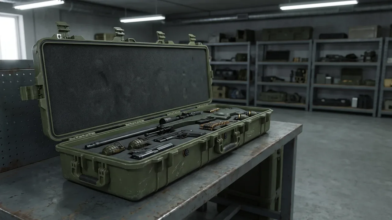
In field handling, vehicle transport, airdrop carry, and warehouse turnover, protective cases are constantly exposed to mechanical shocks such as drops, collisions, and blunt impacts. The IK impact rating grades the shell's ability to withstand mechanical shock in joules of energy; the higher the rating, the greater the margin the case has to protect internal equipment during drops, impacts, and handling knocks. This article focuses on the case itself and systematically explains the grading logic of IK codes, the influence of shell material and reinforcement structure, verification test methods, selection advice, and maintenance points, helping procurement and engineering staff build a practical, verifiable impact-acceptance standard. The grading directly references IEC 62262 (domestic equivalent GB/T 20138) and can be read alongside the IK impact rating case selection and IK impact protection explained articles, combined with the case shell selection guide for structural implementation. A protective case is a system whose impact resistance is decided jointly by shell material, wall thickness, ribs, latches, hinges, and liner; understanding this is the basis for all later selection and acceptance work.
1. Definition and Grading Logic of the IK Rating
The IK code uses two digits to express the enclosure's ability to resist external mechanical impact; the larger the number, the higher the impact energy it can withstand. This grading originates from the international standard IEC 62262, with the domestic equivalent GB/T 20138; the test uses a specified hammer released from a defined height to apply a nominal impact energy to designated points on the sample. The IK rating of a protective case concerns the ability of "the outer shell not to crack or deform to the point of affecting sealing and opening", not the protection of contents by internal cushioning - the latter belongs to liner and vibration-damping design. Understanding this division matters: a high IK rating means the shell resists knocks better during handling, but precision contents inside still rely on the liner to absorb shock energy. Engineering commonly writes the IK rating together with drop height and stacking load into the technical agreement so the impact requirement is quantifiable and verifiable. For stronger structural needs, see the high-strength case structure design notes. In custom practice, the target IK grade is usually set first by loaded mass and environment, then material, wall thickness, and reinforcement are derived backward to meet the impact requirement from the design source.
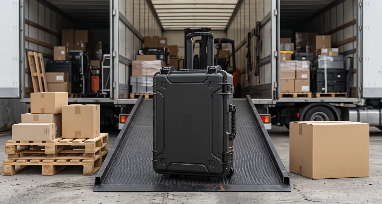
2. IK Codes and Their Joule Energy Correspondence
IK codes rise stepwise from IK00 (no protection) to IK10 (20 joules). Common grades include IK07 at 2 joules, IK08 at 5 joules, IK09 at 10 joules, and IK10 at 20 joules. Each grade specifies hammer mass, impact velocity, and number of impact points, applied repeatedly at weak locations such as case corners, near latches, and the lid centerline. The joule is an energy unit equal to mass times gravity times drop height, so the same energy can be achieved with different hammer combinations, but the standard unifies hammer shape to avoid unfair damage from sharp impacts. Buyers should not merely ask "does it have an IK rating" but rather "which IK grade, under which standard, and how were impact points arranged". These details determine comparability and are the acceptance points repeatedly stressed in the IK impact protection explained article. Note that IK10's 20 joules is roughly the energy of a 2 kg object dropped from 1 meter; this intuitive conversion helps buyers judge whether the grade matches the real drop risk rather than selecting a number blindly. For quick reference, the table below maps common IK codes to nominal impact energy:
| IK code | Nominal energy | Typical use | Intuitive analogy |
|---|---|---|---|
| --- | --- | --- | --- |
| IK07 | 2 joules | Light handling knocks | ~0.2 kg dropped 1 m |
| IK08 | 5 joules | General vehicle turnover | ~0.5 kg dropped 1 m |
| IK09 | 10 joules | Frequent loading | ~1 kg dropped 1 m |
| IK10 | 20 joules | Field drop, hard fall | ~2 kg dropped 1 m |
Emphasize that the table values are nominal energy; actual case performance also depends on material, wall thickness, and reinforcement, so the code alone is never the whole story.
3. Why a Protective Case Shell Needs an IK Rating
A protective case experiences many handling, loading, and transport-vibration events across its life; once the shell cracks or severely deforms, the result ranges from compromised sealing and appearance to loss of protection or even failure to close. The IK rating turns the vague requirement "impact resistant" into a measurable metric: at the same drop, an IK10 case should show no functional crack under 20 joules, while a low-grade case may break after a single hard fall. For high-frequency knock environments such as vehicle, cabin, and field carry, the IK rating is a more reliable basis than "looks sturdy". Note that the IK test targets the empty or specified-state shell; if the case is fully loaded, the actual drop impact becomes more severe due to greater total mass, so selection should work backward from the loaded state rather than the empty rating. The wall-thickness and stiffness relationship is covered in case wall thickness and strength. Only by including the loaded duty in the assessment does the IK rating gain field meaning and avoid the hidden danger of "passing empty but cracking loaded" that undermines the whole purpose of the grade.
4. Distinguishing IK from IP and MIL-STD-810H Shock
IK addresses shell mechanical-impact resistance, IP addresses dust and water ingress, and the two evaluate completely different dimensions that cannot substitute for each other. An IP68 case may excel at sealing, yet if the shell material is brittle and lacks reinforcement it can still crack on a drop; conversely a high IK case is not necessarily sealed. MIL-STD-810H method 516 shock/drop testing, starting from equipment environmental adaptability, specifies more mission-like drop heights, orientations, and counts that complement the laboratory grading of IK. Engineering selection should place the three side by side: use IP for environmental sealing, IK for shell impact resistance, and MIL-STD-810H for overall transport adaptability. For transport adaptability verification, see MIL-STD-810H case compliance and MIL-STD-810H explained. When the three cooperate, the case can both resist environment and withstand impact in real missions, forming complete environmental-mechanical protection instead of favoring one metric and leaving a gap that fails under combined stresses encountered in the field.
5. Influence of Shell Material on the IK Rating
Material is the foundation of the IK rating. Among engineering plastics, modified PP and PE rotomolded have good toughness and impact resistance, suiting low-to-mid energy shocks; ABS and PC alloys are rigid but relatively brittle and need ribs; metals (aluminum alloy, stainless steel) resist deformation strongly, but thin-wall aluminum can still dent under localized heavy blows. Rotomolded cases, being seamless with uniform wall thickness, often perform more stably on impact. Material choice must also consider low-temperature brittleness: some plastics lose impact toughness below -20 C, so cases for cold regions need low-temperature impact verification. For light yet impact-resistant needs, combine the lightweight protective case guide with case engineering versus normal plastic. In custom projects, material is usually recommended by loaded mass and ambient temperature, with corresponding grade verification documents provided so the claimed rating is backed by evidence rather than assertion. Emphasize that after material selection, a drop-weight test should confirm performance; inferring impact behavior from the resin grade alone is unsafe because molding process and wall thickness matter equally. For selection, the table contrasts common shell materials:
| Material | Impact trait | Energy band | Caveat |
|---|---|---|---|
| --- | --- | --- | --- |
| Modified PP/PE rotomold | Tough, seamless | Low-mid | Stiffness via wall and ribs |
| ABS/PC alloy | Rigid, stable | Needs ribs | Brittle, watch cold |
| Aluminum alloy | Strong, light | Mid-high | Thin wall may dent |
| Stainless steel | Strongest | High | Heavy, costly |
After material is chosen, a drop-weight test must still confirm performance, because molding process and wall thickness matter as much as the resin grade itself for the final result.
6. Role of Ribs and Corner Structure in Impact Resistance
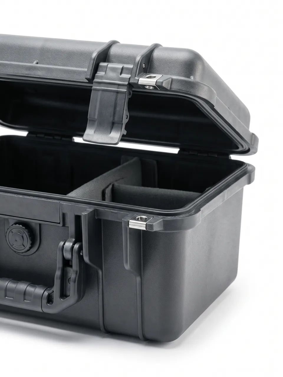
Ribs are the most cost-effective structural means to raise the IK rating. Longitudinal and transverse ribs inside the wall, thickened fillets and corner caps at case corners spread localized impact force over a larger area, avoiding stress concentration that causes cracking. The corner is the most frequently impacted location (corners usually touch ground first on a drop), so corners often use double walls, internal structural foam, or external protective caps. Latch and hinge areas are also stress concentrators and should be locally thickened with rib transitions to distribute load. The design pursues "equal strength" so the weakest point also meets the target grade rather than only reinforcing one face. For structural detail, case reinforcement ribs gives rib layout and section-choice experience, and case rounded corner stresses the value of fillets in lowering stress concentration. These structural measures and material choice jointly determine the final IK rating. In batch customization, finite element analysis should also check corner and latch-point stress to ensure reinforcement truly lands where force is highest, avoiding formalistic "ribs that do not carry load" designs that look strong but fail under real impact.
7. Relationship Between Wall Thickness and Stiffness
Wall thickness directly affects the case's bending stiffness and impact resistance. Once material is fixed, increasing wall thickness raises the section moment of inertia, making the case deform less and stress lower under impact. But thicker is not always better: excess thickness adds weight and cost and may backfire through internal sink marks and uneven residual stress. Rotomolded cases commonly use 3 to 5 mm walls, with key areas (corners, latch points) locally thickened to 6 to 8 mm; injection cases use 2.5 to 4 mm, relying on ribs. Finite element analysis is commonly used to check stress distribution under impact, confirming maximum stress below the material allowable with a safety margin. The quantified wall-thickness and stiffness relationship is detailed in case wall thickness and strength. For large cases, also consider mid-span supports on long sides to avoid overall collapse after impact. Experience shows that each 1 mm of added wall thickness yields limited stiffness gain; the more economical route is moderate wall thickness plus rational ribs, a combination widely used to reach the target IK grade without excessive weight penalty on the final product. The table gives wall-thickness experience by forming method:
| Method | Common wall | Local thicken | Reinforce |
|---|---|---|---|
| --- | --- | --- | --- |
| Rotomold | 3 to 5 mm | 6 to 8 mm at corners | Inner ribs, caps |
| Injection | 2.5 to 4 mm | Latch points | Outer ribs |
| Metal stamp | 1.5 to 3 mm | Hemmed edge | Welded ribs |
Wall thickness is only one stiffness factor; real impact resistance comes from the systematic cooperation of wall, ribs, and material rather than any single dimension tuned in isolation by the designer.
8. Latches and Hinges as Weak Points Under Impact
Latches and hinges are relatively weak connectors on the case; if a latch loosens or a hinge breaks under impact, the lid may open and sealing fails. Improving impact resistance takes three routes: first, choose metal or reinforced-nylon latches to avoid brittle fracture; second, increase latch count and even distribution so impact load spreads; third, use double-axis or thickened-pin hinges with local reinforcement at the mount. In vehicle or airdrop duty, latches should also have an anti-accidental-open self-lock. Latch and hinge durability and materials are covered in case lock customization options and case latch selection, with structural strength in hinge latch design durability. In custom high-IK cases, the latch-point region is usually locally thickened and dual latches are configured to spread corner impact, because a single latch failure can cascade into total protection loss. Note that latches and hinges, though small, are the most failure-prone links in the impact chain and deserve the same attention as the shell during selection and maintenance; otherwise a single connector failure drags down the whole case's protective performance despite an otherwise strong design.
9. Liner Cushioning as Secondary Shock Energy Absorption
The shell's job is "not to break"; the safety of internal equipment depends more on the liner and damping layer's secondary absorption of shock energy. Common liners such as EVA, PE foam, PU foam, and pre-cut foam lower peak transmitted force to an acceptable range through elastic deformation. The liner should conform to the equipment contour to prevent the contents from shifting and causing secondary impacts; for extremely fragile devices, a "hard shell plus soft pad plus locating" combination lets impact first disperse in the shell then absorb in the liner. For liner selection, custom foam lining guide and case internal foam types provide material and structure comparisons. Note that liner cushioning cannot compensate for a cracked shell; the IK rating and liner design must both pass, forming a two-layer "shell resists impact plus liner absorbs energy" relationship that no single layer can replace. In custom projects, liner thickness and hardness should be calculated from the equipment fragility; for example G-sensitive electronics should use foam with a lower rebound threshold so the impact is fully attenuated before reaching the device and causing latent damage.
10. IK Verification Tests: Pendulum, Spring Hammer, and Drop Weight
IK verification commonly uses three devices: a pendulum impactor swings to strike the sample at a specified energy; a spring hammer (bouncing hammer) applies standardized impacts to small enclosures; a drop weight impacts designated points via free-falling mass. Before the test, samples are conditioned at standard temperature and humidity, and impact points cover weak areas such as corners, edges, flat faces, and near latches, with multiple strikes per point followed by inspection for cracks, deformation, or functional failure. The pass criterion is typically "no effect on protection function or opening"; severe cracks or latch detachment is a fail. For batch supply, first-article full IK verification is advised with periodic sampling in production. For test detail, see drop test guide and drop height by weight. Emphasize that the test state (empty or loaded, closing torque) must be stated in the report, otherwise conclusions are not comparable across suppliers or batches. For critical-duty cases, add one full-case drop sample at goods receipt and file the result in the supplier performance record as the basis for later order allocation and claims, closing the loop between lab grade and field reality.
11. IK Rating Selection by Application Scenario
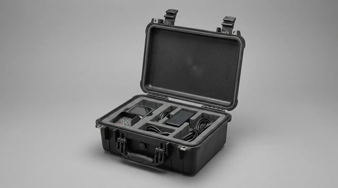
Selection should work backward from the real duty: ordinary warehouse turnover and occasional handling usually suffice with IK07 to IK08; vehicle transport and frequent loading suggest IK09; field carry or possible drops and blunt impacts should reach IK10; airdrop and high heavy-fall risk need overall verification against MIL-STD-810H method 516. Beyond the grade number, consider total case mass - the heavier the load, the greater the impact energy at the same drop height, so the required IK rating should rise accordingly. For medical, communication, and surveying precision equipment, even with a passing IK shell, pair it with liner and locating design. The selection checklist can combine the IK impact rating case selection. Recommend writing the four elements "duty - drop height - loaded mass - target IK" into the procurement technical condition so the grade is not chosen by feel. For tasks crossing temperature zones or transport modes (land, air, sea), take the most severe duty's grade as the acceptance baseline to ensure reliability throughout the whole mission profile rather than only at the easiest segment. The table maps typical duty to target IK:
| Duty | Suggested IK | Extra verification |
|---|---|---|
| --- | --- | --- |
| Warehouse occasional handling | IK07-IK08 | Basic drop |
| Vehicle frequent loading | IK09 | Stack plus vibration |
| Field carry, possible drop | IK10 | Corner edge face drop |
| Airdrop heavy-fall risk | IK10 plus MIL-810H | Method 516 |
Write duty, drop height, loaded mass, and target IK together into the technical condition so the grade is not chosen by feel and the acceptance basis is explicit for both parties.
12. Factory Impact Inspection and Site Sampling
Beyond full IK verification, the line can add simplified drop or knock quick-tests: for example, corner, edge, and face drops from a specified height by loaded mass, checking shell and latch condition. Such quick-tests are low cost and can run 100%, fitting high-volume flow. At goods receipt, buyers can sample a few for the same drop and cross-check the grade and test state against the supplier's IK report. If shell cracks or latch failure appear, re-inspect the whole batch and trace the process. For durability and load inspection, the principle of toolbox durability and load test transfers to case impact acceptance. Be clear that quick-tests do not replace standard IK verification; the two should form a "quick-test controls process, certification controls compliance" partnership, and critical batches should still run the complete IEC 62262 grading test. Recording sample results in the supplier file gradually builds a credible anti-impact quality baseline and reduces later goods-receipt risk, turning inspection data into a continuously improving control rather than a one-time gate.
13. Impact Protection in Transport Stacking and Drops
Transport and stacking amplify impact risk: the higher the stack, the greater the static pressure on bottom cases; sudden braking or careless forklift operation produces instantaneous shock. The case should be designed so stacking corners distribute load evenly, with height limits and "no throwing" marks on the outer case. For air or long-haul land transport, use palletized shipping and lashing to reduce case-to-case collision and sudden-braking shock. If contents are fragile and high-value, add a buffer surround or wooden crate outside the case for "case plus transport outer pack" double protection. For stacking structure, case stacking structure and case stacking corner guide provide corner-load design experience. Managing transport shock as a whole risk avoids the awkward "case itself passes but transport breaks it" outcome that wastes the rating. For multi-parcel consolidated shipping, also use dividers and fill to prevent mutual knocking and sliding that accumulates damage across a long logistics chain and silently degrades the case before it reaches the user. The table summarizes transport shock controls:
| Stage | Risk | Control |
|---|---|---|
| --- | --- | --- |
| Handling | Rough throw | Mark no-throw on case |
| Stacking | Bottom load | Corner load, height limit |
| Transit | Brake shock | Palletize and lash |
| Consolidation | Mutual knock | Dividers and fill |
Treating transport shock as a design input protects the IK grade result at the very end of the logistics chain rather than only at the factory gate.
14. Labeling, Maintenance, and Selection Checklist for IK Cases
A case that reaches the target IK rating should display the actual grade (such as IK10), the executing standard, and manufacturer information in a visible location, and ship with a copy of the verification report so users know its impact boundary. For maintenance, inspect the shell for old cracks, dents, and loose latches before each use; even a non-through crack should be retired or repaired early because micro-cracks propagate under later impacts. For metal cases, also treat rust at corners where the base material is exposed from knocks. The selection checklist should include: duty and drop height, loaded mass, target IK grade and standard, material and wall thickness, ribs and corner caps, latch and hinge specs, liner plan, and verification document requirements. For customers procuring at scale, model-specific seal kits, custom liners, and test documents can be bundled from the first unit so the impact requirement lands on the physical product. Only by closing the loop of labeling, maintenance, and selection does the IK rating deliver across the lifecycle rather than only at the test bench. A per-case maintenance log recording drop count, visual checks, and repairs keeps the impact capability traceable through the service life. At acceptance, write the IK declared grade, the test standard, the impact-point layout, and the pass criterion into the procurement technical agreement, and treat the first-article full verification report as a precondition for batch release. This converts a claim into an enforceable contract clause rather than a slogan on the box. For fleets needing recurring deployment, bundle model-specific seal kits and custom liners from the first unit so the impact requirement lands on the physical product. When staff rotate, these case-attached records keep the rating alive through the archive instead of degrading into an uncontrolled state, letting the real value of IK persist across many years of service rather than only at the acceptance bench.
Lifecycle cost should also enter the selection review. A case with reliable impact resistance and convenient maintenance may carry a slightly higher unit price, yet it amortizes that premium through fewer shell repairs, less lost equipment, and a lower total cost of ownership than a cheap case replaced repeatedly after drops. Procurement teams that score suppliers on verified IK performance, spare-part availability, and documented maintenance guidance see fewer surprises in the field. In practice, organizations that treat IK as a managed process rather than a one-time rating report fewer field failures and a more predictable budget across the equipment service life, which is the ultimate proof that the grade was worth specifying. Documenting each drop event and inspection in the per-case log also builds a dataset that predicts when a case should be retired, turning maintenance from reactive to planned. A practical acceptance habit is to photograph the IK label at goods receipt and store the image with the batch record, so years later the exact declared grade is still known without opening the archive. For organizations procuring at scale, asking the supplier to bundle model-specific seal kits, custom liners, and test documents from the first unit turns labeling, traceability, and maintenance into physical deliverables instead of paper promises, which is the most reliable way to keep the rating meaningful over many years of field service and rotating personnel.
FAQ
Q: Are the IK rating and "drop proof" the same thing? A: Not exactly. The IK rating, per IEC 62262 / GB/T 20138, grades the shell's ability to resist mechanical shock in joules of energy, focusing on whether the outer shell cracks or deforms to affect function under impact; "drop proof" is a more colloquial combined claim that often also includes the liner's protection of internal contents. Simply put, a high IK means the shell resists knocks, but precision contents inside still depend on the liner to absorb energy. Therefore selection should evaluate the IK rating (shell impact) and liner cushioning (internal absorption) separately, and both must pass to be truly drop resistant. A case that only labels "drop proof" without a specific IK grade and standard makes its impact ability hard to verify, so buyers should demand the explicit grade and test state. Writing both metrics into the technical agreement turns them into enforceable, auditable constraints rather than marketing phrases, and gives a clear basis for acceptance inspection at goods receipt.
Q: How do I judge whether an IK rating is genuine when purchasing? A: Check three things. First, the report should cite IEC 62262 or GB/T 20138 and state the specific IK code such as IK10. Second, the test state must be clear, including empty or loaded, closing torque, impact-point layout, and strikes per point. Third, the impact energy and hammer parameters should match the target grade. Missing any element makes the conclusion incomparable. Ask the supplier for a third-party or first-article full verification report and agree the sampling method in the contract. At goods receipt, run a sample re-test per the drop test guide and cross-check the grade against the report to avoid being misled by vague "high impact resistance" claims. Only when standard, state, and parameters all appear in the report does the grade become verifiable rather than decorative, and only then can it serve as the basis for acceptance and downstream warranty or claim actions between the buyer and the supplier.
Q: Is a heavier case always more impact resistant? A: Not necessarily. Greater mass does mean greater impact energy at the same drop height and a harder test on the case, but "impact resistance" depends on material, wall thickness, ribs, and structural design, not merely weight. A well-designed light rotomolded case may outperform a thin, unribbed metal case; conversely an over-heavy case with uneven structure may crack more easily from stress concentration on a drop. Selection should look at the IK rating and verification documents, not the feel of the weight. Also work backward from the total loaded mass, because the heavier the contents, the more severe the real drop impact. Quantified structural strength can be referenced in case wall thickness and strength and high-strength case structure. Using grade and verification as the criterion avoids being misled by surface weight and truly selects an impact-reliable case instead of one that merely feels solid in the hand during a showroom check.
Q: Can a liner replace a high-IK shell? A: No. The liner and damping layer absorb the shock energy transmitted to the equipment, protecting the "internal objects"; the IK rating protects the "outer shell from breaking or deforming to affect sealing and opening". If the shell cracks or the latch detaches under impact, no liner can stop water, dust, or contents scatter. The two form a "shell resists impact plus liner absorbs energy" two-layer relationship that must both pass. Engineering recommends first setting the target IK grade by duty to secure the shell, then designing liner conformance and locating by equipment sensitivity to form complete protection. For extremely fragile devices, a hard shell plus soft pad plus locating combination lets impact disperse first then absorb. Shell and liner each play their role; missing either creates a weakness, so verify both metrics separately at selection and never let one substitute for the other during the specification or the field use of the case. A practical rule is to verify the shell grade by impact test and the liner by drop-testing the loaded case, so both layers are proven rather than assumed, which prevents the common mistake of trusting a high IK number while ignoring a poorly fitted liner that lets the contents rattle and crack on the first real drop.
Q: Does the IK rating change in low-temperature environments? A: Yes. Many plastics lose impact toughness at low temperature, showing "cold brittleness"; an IK10 case at -30 C may perform markedly worse. Therefore cases for cold regions or high-altitude and arctic duties should require the supplier to run IK verification after low-temperature conditioning, not just provide a room-temperature report. On material, rotomolded modified PP and PE generally have better low-temperature toughness than ordinary ABS; metal cases are unaffected by cold brittleness, but surface coating and liner still need low-temperature consideration. Write the operating temperature range into the technical agreement and note the verification temperature to truly match cold-region duty and avoid the hidden danger of passing at room temperature but failing when cold. For cross-temperature transport, use the most severe temperature segment's verification as the acceptance basis so the rating does not silently degrade across the mission and leave the contents exposed to an unverified condition. Requesting the cold-temperature report up front is far cheaper than discovering brittle failure after a winter deployment in the field, where a cracked shell can mean a total loss of the protected payload. In practice, specifying the low-temperature verification up front costs almost nothing yet prevents the most expensive possible failure, so it should be a standard line in every cold-region procurement clause and a routine check during incoming inspection for arctic or high-altitude missions.
Q: Does a broken latch or hinge affect the IK rating? A: Greatly. Although the IK test evaluates the shell as a whole, latches and hinges are the key parts connecting lid and body; if a latch loosens or a hinge breaks under impact, the lid may open and sealing fails, equaling total protection loss. Therefore high-IK cases must locally thicken the latch-point region and use metal or reinforced-nylon latches, thickened-pin hinges, and dual latches when needed to spread corner impact. In daily maintenance, replace a loose latch or abnormal hinge promptly; never use it while defective. For latch and hinge selection, see case lock customization options and hinge latch design durability. Managing connectors as a life item keeps the IK rating effective long term, because a single-point failure can drag down the whole case's protection performance and waste all the earlier investment in a strong, well-reinforced shell that was supposed to earn the grade. As a practical rule, record latch and hinge inspection in the per-case maintenance log and the pre-deployment checklist, so any wear is caught before it turns into an open-lid failure in the field. Treating those small parts as scheduled service items is the cheapest insurance that the certified impact grade survives real use.
Q: How do I reduce impact damage during transport? A: Treat transport shock as part of overall risk control. First, mark height limits and "no throwing" on the outer case to avoid rough handling; second, use palletized shipping and lashing to reduce case-to-case collision and sudden-braking shock; when stacking, let stacking corners distribute load and do not exceed the marked height. For fragile high-value contents, add a buffer surround or wooden crate outside the case for "case plus transport outer pack" double protection. For stacking structure, case stacking structure provides corner-load experience. After receipt, sample re-test per the drop test guide to catch hidden transport damage before use. Treating transport shock as a design input rather than an afterthought maximizes protection of internal equipment and preserves the value of the IK rating through the whole logistics chain, so the case that passed the lab still performs when it finally reaches the field user after a long, punishing journey. A simple pre-shipment photo of the case condition and a signed transport checklist also deters rough handling and gives a clear record if a claim becomes necessary after delivery, closing the loop between the verified grade and the received condition.