

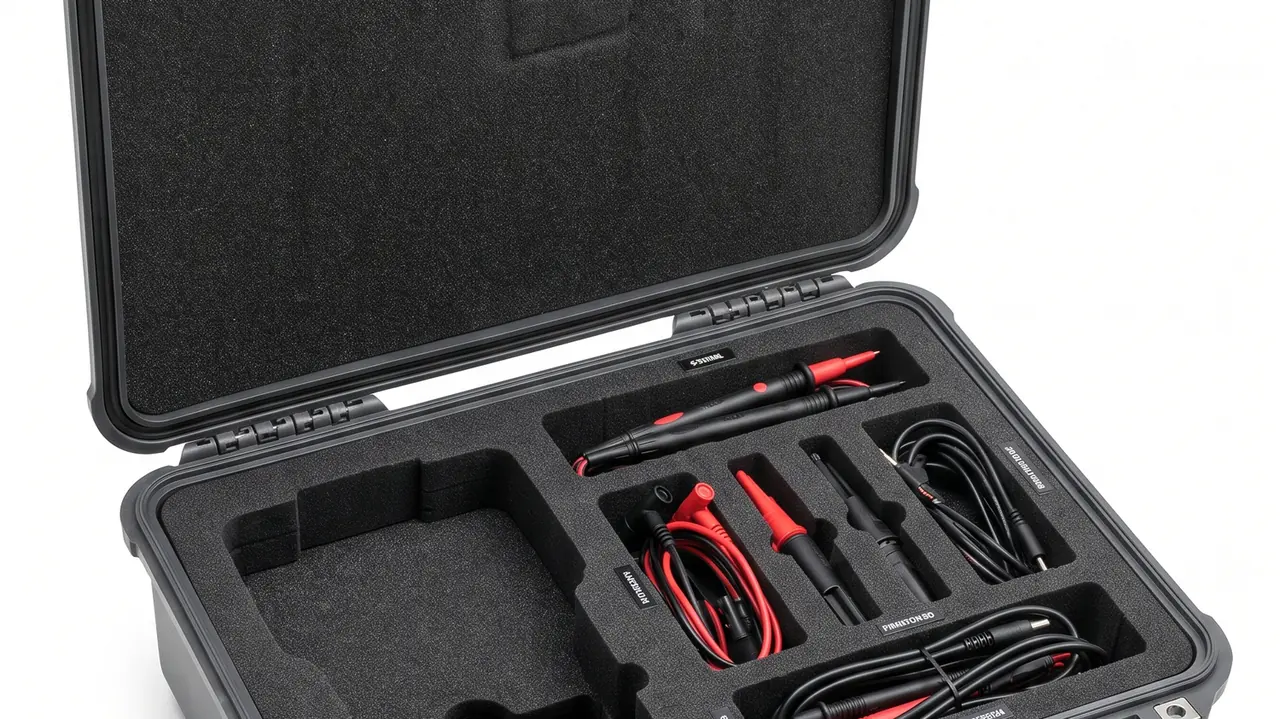
Reactor coolant pump assemblies, gate and safety valve internals, instrument tubing and control rod drive mechanisms all belong to the class of parts that leave no room for a second attempt once they arrive. Protecting them in transit is not simply a matter of padding. Cleanliness, vibration control and moisture control have to hold at the same time: a single hard particle can bruise a sealing face, a sustained resonance can alter pump shaft straightness, and one condensation cycle can leave a stainless surface already pitted on arrival. The conclusion up front: a nuclear power component case should treat cleanliness, vibration isolation and foreign material exclusion as its first design targets, locating every item in a contour-machined compartment liner, governing packing environment and internal passages under ISO 14644 and ISO 4406 respectively, and holding a stable microclimate behind IP67 sealing and a pressure equalization valve, with lift points and locating features calculated for tonne-class items. The sections below work through each component family with the structure, material, test and acceptance details that follow from it.
Failures in this field rarely originate on the manufacturing floor. After cleaning and dimensional release, a part usually travels by road, sea and air into a station warehouse, then moves again to the building during an outage window, passing through repeated hand-offs, short open-air holds and climate swings. A wooden crate with stretch film and a trestle neither restrains a tonne-class casting nor keeps out moisture and dust, and by the time the lid comes off the correction costs far more than a purpose-built case would have. Putting the case into the procurement specification, and managing it with the same process discipline as the part itself, is one of the highest-yield steps available in nuclear island spares management. Procurement engineers and equipment owners can use this article as a selection and acceptance checklist.
Table of Contents
- 1. Three Constraints in Nuclear Island Component Transit
- 2. Cleanliness Control: ISO 14644 and ISO 4406
- 3. Lifting and Locating Heavy Parts: Pump Casing and Shaft
- 4. Vibration Isolation: Shaft, Impeller and Inline Instruments
- 5. Gate and Safety Valves: Seats and Sealing Faces
- 6. Instrument Tubing and Fittings: Anti-Buckling and Port Capping
- 7. Control Rod Drive Mechanism: Slender Parts and Vertical Transit
- 8. Moisture, Pressure Differential and the In-Case Microclimate
- 9. Material Compatibility, Outgassing and Restricted Substances
- 10. Case Frame, IP Sealing and the Lightweight Trade-Off
- 11. Environmental Test Methods: MIL-STD-810H and GB/T 4857
- 12. Acceptance, Inspection Documents and OEM/ODM Delivery
- 13. Selection Table and Typical Applications
- Frequently Asked Questions
1. Three Constraints in Nuclear Island Component Transit
A nuclear station asks more of arrival condition than most industries do. Parts are typically released clean, dimensionally verified and packed at the works, then go straight into an installation sequence with no room to rework in between. The four families named above span a mass range from a few kilograms to several tonnes and a geometry range from thin-wall tube to eccentric casting, yet they share the same three constraints.
The first is cleanliness. A hard particle embedded in a sealing face or a ferrule cone can create a dent that cannot be repaired, and such damage usually only shows up at hydrostatic test. Debris generated by the case itself, coating flakes and foam dust are just as much foreign material, which is why nuclear work manages all of it under a foreign material exclusion (FME) regime built on denying foreign material any route in and any place to lodge, rather than on cleaning up afterwards.
The second is vibration. Shafts and impellers are sensitive to straightness and balance, inline instruments are sensitive to shock and mounting stress, and a safety valve derives its set pressure from a spring, so a single over-threshold shock is enough to shift the set point in a way no visual check will reveal before installation.
The third is moisture. Stainless steel is not immune; it pits and suffers crevice attack in humid atmospheres carrying chloride or sulphur species. Since parts often sit in store and in transit for a long time after cleaning, once the dew point crosses the internal surface temperature, condensation appears exactly where it must not: at the root of a seal groove, on the bore of a bolt hole, in the clearance between a stem and its packing.
One point should be stated plainly. A protective case is not nuclear safety-related equipment, and nothing described here constitutes a nuclear grade qualification or certification claim. What the case contributes is structural strength, cleanliness discipline, microclimate control and material and test records that can be tied to a lot number.
2. Cleanliness Control: ISO 14644 and ISO 4406
Cleanliness is not an adjective describing how something looks; it is a graded, quantified specification. Packing and boxing areas can follow the ISO 14644 air cleanliness class concept, specifying a permitted particle count per unit volume in the working zone. Internal passages such as hydraulic circuits and actuator bores are better governed by ISO 4406 cleanliness codes, which set particle size bands and population levels for the fluid or the wetted volume. The two address different objects and should appear as separate clauses in the specification, with the applicable part families named, rather than being collapsed into one vague sentence.
Four hard requirements follow for the case itself. The liner must not shed: machined foam faces should be sealed at the edge or film-faced so that sustained vibration cannot release dust. Nothing friable goes inside: paper labels, loose foam blocks and wood shavings all break down into particles in transit and should be replaced with wipeable soft pouches. Every opening is capped: flanges, pipe ends, ferrules and nozzles receive a plug or dust cover of the correct size, and the plug itself must not become a contamination source. Cavities must be wipeable: internal corners are radiused so there is no dead pocket to trap debris.
Verification belongs upstream of the shipment. A high-cleanliness part can carry a cleanliness indicator label inside the cavity, or be subject to a wipe sample to an agreed procedure, so the reading is available the moment the lid opens, while contamination is still easy to deal with. The boxing area should be physically separated from grinding, abrasive cutting and sawing, and operators should work a tool-accounting and cavity recheck routine consistent with FME practice. That routine is the same discipline applied when the part itself was built, and a case, being one link in the logistics chain, should be inside that discipline rather than an exception to it. Liner machining practice is covered in EVA foam insert custom process, and tolerancing and material choice in custom foam inserts guide.
| Component family | Critical surface | Cleanliness basis | In-case provision |
|---|---|---|---|
| --- | --- | --- | --- |
| Pump casing, flanges, nozzles | Seal grooves, machined faces | Capped ports, visually particle free | Contour cradle, face covers, non-shedding cavity |
| Gate and safety valve internals | Hardfaced seats, guide faces | ISO 4406 code by agreement | Soft shrouds, VCI paper, individual cells |
| Instrument tubing and ferrules | Tube ends, ferrule cone | Single-item caps, item count | Length-keyed slots, size-keyed bins |
| Control rod drive shaft | Fits, plated surfaces | Particle free, oil free | Multi-point equal spacing, wrap film |
3. Lifting and Locating Heavy Parts: Pump Casing and Shaft
A reactor coolant pump casing is a tonne-class casting with an offset centre of gravity, nozzles and flange bosses, and it sets the most demanding load case in the whole case design. Design should work backwards from the load path: part weight travels through the contour cradle into the case base, the base spreads it into the ribs, and the lift corners and forklift slots then carry the dynamic load. Lift points are sized on loaded case weight multiplied by a dynamic factor, not on static weight, because the shock at a set-down is routinely several times the static figure, and that is the single most under-estimated number in heavy case work.
A pump shaft poses a different problem. It is slender, carries fitted diameters and a plated surface, and two supports at mid-length leave self-weight enough to bend it by an amount that is hard to see. The workable arrangement places three to five equally spaced V-cradles along the shaft, lines the cradles with soft facing, and adds axial restraint at both ends so that braking cannot slide the shaft and score a fitted diameter. Impellers and diffuser rings get their own cavities and are never stacked in the same cavity as a shaft.
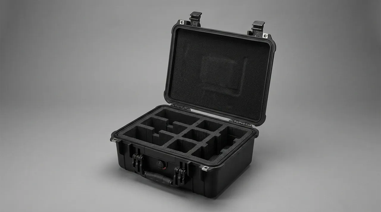
For very heavy assemblies, splitting the shipment is the practical answer: casing, shaft, impeller and seal package travel in separate cases, so each unit needs smaller handling gear on site, fewer lifting operations and a shorter exposure window. Casters and handles are also sized with margin against loaded weight; heavy castors suit short in-plant moves, while long-haul transport removes the castors or fits a rigid brace so the wheel set does not become a vibration transfer path. General heavy-part practice is set out in pressure vessel component case and hoist component case.
4. Vibration Isolation: Shaft, Impeller and Inline Instruments
Vibration risk on nuclear components is largely cumulative. No single excursion is dramatic, but hours or days of road and sea vibration produce fretting at fitted surfaces, loosened fasteners and drifted instrument calibration. Damping therefore has to be verified against an environmental test method rather than settled by adding foam thickness.
Two stages are normal. Stage one is the cavity cradle, where foam working with a rigid backing cradle carries part self-weight so the item neither hangs nor shifts. Stage two is a buffer layer between liner cavity and outer shell that absorbs residual energy from a drop or impact. The two must have an explicit division of labour: the cradle handles location and static load, the buffer handles energy absorption. Blending them into a single undifferentiated layer usually fails both tests at once.
Inline instruments such as transmitters, level probes and temperature elements are better served by their own cavity, isolated on their own damping, with a Faraday layer in the case so that friction against tools or metal parts during transit cannot build static charge. The approach parallels ESD shield case. When selecting vibration and shock conditions, refer to the method basis described in MIL-STD-810H case compliance, noting that the standard is used here as a test method only.
5. Gate and Safety Valves: Seats and Sealing Faces
Valve protection comes down to three faces and one spring. The three faces are the hardfaced seat, the guide face on the disc or gate, and the flange ring groove. The spring is the safety valve set spring. Seat and guide rely on metal-to-metal fit for sealing and guidance, so any impact leaves a consequence that cannot be corrected in the field. The spring is subtler: stored under compression for a long period it relaxes, and a drop can change its free length, either of which moves set pressure away from the design value.
A workable in-case arrangement puts body, bonnet, disc, stem, spring and packing in separate cells, with the spring stored free and never pre-compressed. Seat faces and flange ring grooves take a soft shroud lined with vapour-phase inhibitor paper. A slender stem rides in multiple cradles with axial restraint. Dissimilar metals must be separated: bodies are commonly cast or forged carbon or low-alloy steel while stems and seats are stainless or nickel-based hardfacing, and poor division inside a liner, combined with a damp environment over a long store, creates a galvanic couple.

General valve practice is described in refinery valve case. Where a project requires a valve to travel fully assembled, the liner should be a contour cradle built to the assembled outline, restrained laterally with webbing, and it must still carry a stem-end protective sleeve: a bent stem is far more than the cost of a packing replacement.
6. Instrument Tubing and Fittings: Anti-Buckling and Port Capping
Instrument tubing looks slight but generates a disproportionate share of rework. Small-bore stainless tube, commonly a quarter inch to one inch, has a thin wall and is scrapped once bent past its allowable radius. A ferrule cone or nut that takes a knock may still leak after make-up. And ferrules, back ferrules and nuts of different sizes, mixed together in a parts tray, are effectively indistinguishable at site.
Three rules govern packing: slot by length, bin by size, cap every item. Tubing is laid in slots milled to the measured length with continuous support at the base so no span is left unsupported. Ferrule bodies, front ferrules, back ferrules and nuts go into separate labelled bins with the size marked. Every tube end gets a correctly sized plastic cap. For nipples, stubs and tees that carry a weld bevel, end protection matters most, because a bevel is a weld interface and a burr raised by contact with a hard object means remachining.
Transmitters, pressure switches and similar small instruments are better shipped in a separate case or a separate compartment, because the exposure differs: tubing fears bending, while instruments fear shock and static. Where they must share a case, leave a full buffer around the instrument and never let tubing lay weight onto an instrument face.
7. Control Rod Drive Mechanism: Slender Parts and Vertical Transit
A control rod drive mechanism comprises slender rods, a travel housing, a seal housing and coil assemblies. It combines a high slenderness ratio, tight fits and a surface treatment that cannot be scratched. For parts in this class, the transport attitude matters more to the outcome than the strength of the case.
Under horizontal transit, a long rod sags at mid-span under its own weight. If support spacing is too wide, a small permanent set can remain after unloading and then disturb assembly and running clearance. Support spacing should therefore be derived from the slenderness ratio so that a number of equally spaced, coaxial cradles share the load, with an adjustable support at mid-span where needed. Vertical transit is more robust: a dedicated frame with a base cradle and an upper guide ring loads the rod predominantly in compression and removes self-weight bending at its source.
For surface protection, fitted diameters and plated sections are wrapped in neutral film and interface threads get protective sleeves. No loose metal parts or tools are carried inside the case, because anything free will find a way to collide. General actuator practice appears in linear actuator case and shaft support thinking in shaft coupling case. The vertical frame must be rigidly tied into the case frame; foam alone cannot be trusted to hold a vertical assembly, since the failure mode there is overall toppling rather than local movement.
8. Moisture, Pressure Differential and the In-Case Microclimate
Storage and transit cycles in nuclear work are long, which makes humidity the more persistent threat than temperature. Condensation forms when the dew point of the case atmosphere exceeds internal surface temperature, and three situations trigger it: a shipment from a cold region into hot humid air, repeated day-night temperature swings on a sea leg, and a part that leaves the works still warm after cleaning.
Each needs a different response. Cross-climate transport is handled with desiccant and a humidity indicator card, the desiccant quantity calculated from internal volume and expected transit duration and the card positioned where it reads at first opening. Sea legs depend on sealing class being genuinely delivered, plus a salt-resistant breather element on a defined renewal interval. Residual heat is a process problem: a part should cool to near ambient before the lid is closed, and where the outage schedule will not allow that, the case must carry a pressure equalization valve so expanding and contracting air can move in and out while an ePTFE membrane blocks water and dust.
The pressure equalization valve matters especially for air freight and long hauls. A case closed in a cold or low-pressure location will gain internal pressure in a hot destination, and the rush of air at opening can carry external dust into a cavity that was clean. The reverse case, contraction drawing a vacuum that grips the lid, invites damage when someone forces it, permanently deforming the gasket. Structure and selection detail is covered in case pressure equalization valve and IP67 protective case.
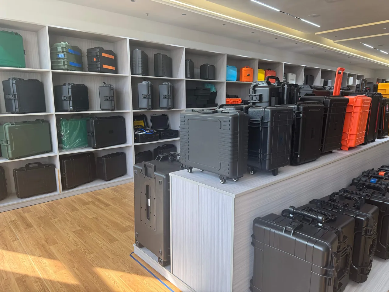
Desiccant belongs in a lid mesh pouch or a dedicated cell, physically separated from the parts so that once it takes up moisture its powder cannot settle on a sealing face. For machined surfaces prone to rust, vapour-phase inhibitor paper can establish a local protective atmosphere at the same time, but VCI does not absorb moisture and is not a substitute for desiccant; the mechanisms are complementary, not interchangeable. A colour change on the humidity card means the part was exposed to moisture and should be dried to procedure and logged before it goes onto the plant.
9. Material Compatibility, Outgassing and Restricted Substances
Materials that touch a part, directly or indirectly, are participating in its corrosion control, so selection cannot rest on mechanical properties alone. The first principle is avoiding galvanic coupling: the material combination of cradle, divider, fastener and part body should be checked in advance, and zinc-plated or plain carbon steel items should not sit against stainless parts over long periods, particularly where chloride is present.
The second principle is controlling outgassing and corrosive volatiles. Foams, adhesives and gaskets should be low-VOC and low-outgassing grades, sulphur free and halogen free. Sulphur-bearing rubber is actively harmful to silver-plated and copper-alloy terminals, and halogen-bearing materials release ions in damp conditions that accelerate pitting. Closed-cell foam, unlike open-cell, does not absorb water or shed particles and suits long-term storage better.
The third is flame retardance and static control. Case and liner materials should meet UL94 flame requirements to reduce risk near electrical cabinets or powered equipment. Where a part carries an electronic tag or a sensitive circuit, the liner should be a static-dissipative grade, with surface resistivity held in the dissipative band rather than the insulating band. Material trade-offs are compared in case foam material comparison and case seal materials. Every material supplied with the case should come with a material statement, issued as part of the delivery file so that station receiving can reconcile it against the packing list.
10. Case Frame, IP Sealing and the Lightweight Trade-Off
The strength ceiling of a case frame is set by its load path, not by wall thickness. The right approach routes load along ribs into lift points and the case base, keeping concentrated stress away from latches and hinges, which should only be asked to close and hold. Tonne-class items need the base and lift corners calculated in their own right; for hand-carried cases, the priority shifts to local reinforcement where the handle meets the wall.
Sealing class is normally specified to IP67 (IEC 60529 / GB/T 4208), covering dust-tightness and short immersion. The difficulty sits in a large lid: the gasket must be a continuously moulded EPDM or silicone ring seated in a machined groove, and latches must be spaced so the ring is loaded evenly from end to end, verified by sampled spray or immersion testing rather than by feel. Hinges and latches are high-cycle parts whose structural strength and sealing function are two separate design problems, addressed in toolbox hinge latch seal.
Weight reduction involves a real trade-off. Air-freight projects are sensitive to gross case weight and can be optimised with an aluminium frame and thinned non-structural panels, but weight must not come out of the load path, or the freight saved returns as a cracked case at the first lift. Road and sea projects weigh stacking strength and weather resistance more heavily, and external finish should be an epoxy primer under polyurethane topcoat, assessed to the GB/T 10125 neutral salt spray method and reported as hours to red rust.
11. Environmental Test Methods: MIL-STD-810H and GB/T 4857
Transit verification for these cases should cover vibration, shock, temperature-humidity cycling and salt spray. MIL-STD-810H is used here purely as an environmental test method basis, to standardise conditions and pass-fail language, and it does not constitute any military certification; that wording appears explicitly in the delivery documentation. Domestic projects can combine the GB/T 4857 series of transport packaging test methods, with ISTA or ASTM D4169 distribution cycle simulation selected according to project requirements.
| Test | Method basis | Typical condition (experience values) | What is judged |
|---|---|---|---|
| --- | --- | --- | --- |
| Random vibration | MIL-STD-810H Method 514 (method reference only) | 5-500 Hz, road and air profiles set separately | No cavity collapse, no part movement, no cradle crushing |
| Drop and shock | MIL-STD-810H Method 516, ISTA series | 1.2 m corner-edge-face drop, graded by weight | No frame cracking, buffer not pierced, lift points undeformed |
| Temperature-humidity cycling | MIL-STD-810H Method 507 | High-humidity hot dwells with cold transitions | No internal condensation, card unchanged, gasket not permanently set |
| Neutral salt spray | GB/T 10125 | Agreed exposure cycle with recorded result | Hours to red rust on metal fittings and fasteners |
The value of testing is that it turns design assumptions into comparable records. A drop test exposes weld quality at a lift corner; a vibration test reveals excessive clearance between cradle and liner. The test plan should be fixed at design stage rather than retrofitted afterwards, because once a load path needs changing, what changes is liner tooling and base structure, not a strap. Related method notes appear in ISTA transport testing procedure and GB/T 4857 transport packaging.
12. Acceptance, Inspection Documents and OEM/ODM Delivery
Acceptance of a production batch turns on what can be reconciled, not on what looks good. A risk-based item check with AQL sampling works well: confirm that each item has its own cavity, that dissimilar metals are separated, and that frame and lift corners are rated for loaded weight; check material statements for cradles, dividers and fasteners; check the sealing verification record; check results for the agreed cleanliness items; and check that the pressure equalization valve, desiccant and humidity cards are all present.
Documentation is a line item in its own right and must be bound to the lot number: material certificates, salt spray records to GB/T 10125, vibration and drop records to the agreed method, flagged to note that MIL-STD-810H is a method reference and not a military certification, cleanliness inspection results, and the packing list with the boxing record. A lot without records should not be released to store as a matter of principle. Sampling detail is described in custom case acceptance AQL.
Two delivery routes are available for this work. An OEM programme applies a customer drawing and brand to a standard shell and suits projects that already have a settled cavity design and want fast supply of identical cases for spares across several stations. An ODM programme begins at cavity measurement and load-path design, which suits main pump castings and slender rod assemblies that need a dedicated liner built to the real outline. Both routes can be delivered with material and test files, support wholesale, agency and global supply, and define cavity tooling ownership and reuse up front. Factors for evaluating a works are listed in how to choose case OEM factory.
13. Selection Table and Typical Applications
Protection requirements differ sharply between component families, and forcing them into one specification tends to fail on exactly the item that mattered. The table gives the configuration direction by family, for use when drafting a specification.
| Item | Mass class | Liner form | Frame and lifting | Sealing and microclimate |
|---|---|---|---|---|
| --- | --- | --- | --- | --- |
| Pump casing | Tonne class | Contour cradle plus locating pins, face covers | Forklift slots and four lift corners, dynamic load basis | IP67 with pressure equalization valve |
| Pump shaft, impeller | Hundreds of kg | Multiple V-cradles with axial restraint | Multi-point horizontal supports or dedicated vertical frame | Moisture control with VCI paper |
| Gate and safety valve internals | Tens to hundreds of kg | Separate cells with soft shrouds | Reinforced base and webbing rings | Moisture control with cleanliness card |
| Instrument tubing, ferrules | A few kg | Slots by length, bins by size | Reinforced hand-carried shell | Moisture control with capped ports |
| Control rod drive shaft | Tens to hundreds of kg | Multi-point equal spacing, coaxial cradles | Vertical transit frame tied into the frame | Moisture control with wrap film |
Three application patterns cover most demand. The first is the long-haul movement from works to an outage site, where cumulative vibration and temperature-humidity cycling dominate and the case must accept sea stacking and repeated lifting. The second is long-term storage in a station spare warehouse, where gasket durability and the desiccant and card renewal interval matter most, and where a wipeable, recheckable cavity counts for more than strength. The third is short in-plant transfers during an outage window, where fast opening and lifting efficiency dominate and the ergonomics of latches, hinges and lift points feed directly into schedule. The three can share one outer shell specification, but liner and accessory sets should be defined per pattern. Cleaning and reuse practice is covered in how to clean protective case, and service life assessment in protective case service life years.
Frequently Asked Questions
Q: What really separates a nuclear component case from a precision instrument case? A: The difference is in the governing specification and the control targets, not the outline. An instrument case mainly answers one question, whether the item survives transport intact, and the criteria are appearance and basic function. A nuclear island component case has to satisfy cleanliness, vibration and moisture simultaneously, so the criteria extend into particle control in the working zone, a cleanliness code for internal passages, and pitting resistance for stainless steel over long damp storage. Structurally, an instrument case is often one foam layer with dividers, while this class needs a rigid backing cradle carrying tonne-class self-weight, a separate buffer layer absorbing shock energy, and an individually wipeable cavity per item. Procedurally, packing an instrument case is a logistics action; packing a nuclear case is a process control action requiring FME tool accounting, opening-cap records and cleanliness inspection results. Put those three clauses into the specification rather than the phrase shock, water and corrosion resistant. A case that answers only the transport question can pass a visual check and still fail the cleanliness one.
Q: How should in-case cleanliness be specified and verified? A: Two object classes are governed differently. The boxing environment follows the ISO 14644 cleanliness class concept, specifying permitted particle counts per unit volume in the working zone. Internal passages and hydraulic bores are better governed by ISO 4406 cleanliness codes, which set particle size bands and population levels. Verification leans on visual inspection, indicator labels inside the cavity and wipe sampling, with particle counting for higher-risk items. Two mistakes recur. The first is treating ambient cleanliness as part cleanliness and ignoring debris the case generates itself as liners wear. The second is inspecting once and reusing indefinitely, ignoring cumulative shedding and trapped debris. Practical countermeasures are sealing machined foam edges, radiusing internal corners, capping every opening, keeping friable paper and timber out of the case, and binding every inspection result to the lot number so a receiving check can follow the trail. The two bases should be written as separate clauses naming the part families they govern, because one figure that satisfies an air cleanliness class says nothing about particles resting inside a machined bore.
Q: How are tonne-class items such as a main pump casing lifted and secured? A: Three things carry the load: a contour cradle, multi-point restraint, and lift points sized on dynamic load. The cradle is machined to the measured casing so the centre of gravity rests on a load-bearing face rather than hanging, the base carries forklift slots and lift corners, and ribs under the base spread the concentrated load into the case walls. Webbing through fixed internal rings limits lateral and vertical movement, and locating pins through flange bolt holes stop rotation. Lift points are calculated on loaded case weight times a dynamic factor, never on static weight, because a set-down shock can be several times the static figure. For very heavy assemblies, split the shipment: casing, shaft, impeller and seal package in separate cases lowers unit weight, reduces the handling gear needed on site and cuts the number of secondary lifts. Close with a physical recheck, rocking the case by hand for rattle, confirming webbing tension and checking lift corners for deformation, and log the result.
Q: Why do stainless steel parts still need moisture control? A: Because the corrosion resistance of stainless steel depends on a passive film that chloride or sulphur species in a damp atmosphere can break down locally, driving pitting and crevice attack. Crevices are the most dangerous locations. Bolt hole bores, the root of a seal groove and the clearance between a stem and its packing accumulate condensation and salt, and they are poorly ventilated, so corrosion starts there first. Nuclear spares often sit in store for months and move across climate zones, and one sea leg is enough to push internal humidity across the dew point repeatedly. The response combines desiccant with a humidity indicator card behind IP67 sealing, a pressure equalization valve to stop the air rush at opening from carrying dust inward, and VCI paper for local protection of machined surfaces prone to rust. VCI does not absorb moisture and cannot replace desiccant, so the two are used together rather than one instead of the other.
Q: How do you keep a control rod drive shaft from bending in transit? A: Support spacing and transport attitude decide the outcome. Under horizontal transit, a long rod sags at mid-span, and wide support spacing leaves a small permanent set that later disturbs assembly clearances, so spacing should be derived from the slenderness ratio with multiple equally spaced, coaxial cradles, soft-faced cradle mouths and axial restraint at both ends to stop braking from sliding the rod and scoring a fitted diameter. Vertical transit is more robust still: a dedicated frame with a base cradle and an upper guide ring loads the rod predominantly in compression and removes self-weight bending at source. The vertical frame must be rigidly connected to the case frame, because foam alone cannot restrain a vertical assembly whose failure mode is overall toppling rather than local movement. For surface protection, wrap fitted and plated sections in neutral film, sleeve interface threads, and keep loose metal and tools out of the cavity entirely. These steps cost little against realigning a shaft whose running clearance has already closed up.
Q: Is MIL-STD-810H a certification for a nuclear component case? A: No. It is used only as a basis for environmental test methods, and it grants no certification of any kind. Its practical value is standardising vibration, shock and temperature-humidity conditions so that results from different batches and different suppliers can be compared on the same terms. Method numbers are cited to set conditions, and every delivery note and acceptance file states explicitly that this is a method reference and not a military certification; no military or nuclear grade qualification is claimed anywhere in the documentation. Domestic projects can combine the GB/T 4857 series for transport packaging, and distribution cycle simulation can follow ASTM D4169 or an ISTA procedure. Judgement should land on specific features: whether a cavity collapsed, whether a cradle crushed, whether a lift corner deformed, whether condensation appeared inside the case. Citing a method is not the same as holding a certificate, and procurement documents should not blur the two. Keep the method citation and the disclaimer in the same paragraph of the test report, so no reader can quote one without the other.
Q: Can the materials inside the case become a contamination source? A: Yes, and it is the easiest source to overlook. Three risks need separate handling. The first is debris: foam cut faces that are not edge-sealed or film-faced shed dust under sustained vibration and contaminate sealing faces directly, while paper labels, timber and loose foam blocks break down the same way and should give way to wipeable soft pouches. The second is outgassing and corrosive volatiles: adhesives and gaskets should be low-VOC and low-outgassing, sulphur free and halogen free, because sulphur-bearing rubber attacks silver plating and copper-alloy terminals and halogen-bearing materials release ions that accelerate pitting in damp conditions. The third is static and flame performance: parts with electronic tags get a static-dissipative liner, and case materials should meet UL94 flame requirements. Every material travelling with the case should come with a material statement so station receiving can reconcile it against the packing list. Any material substitution made during production needs written approval before the case leaves the works.
Q: How is a batch inspected and documented before it enters the store? A: Work item by item against the risk classes, sample with AQL, and treat documentation as its own line item. Structure first: each item in its own cavity, dissimilar metals separated, frame and lift corners rated for loaded weight, casters and handles sound. Materials next: statements for cradles, dividers and fasteners, with particular attention to anything sitting against stainless parts. Performance after that: the sealing spray or immersion record, salt spray hours to GB/T 10125, and vibration and drop records to the agreed method. Cleanliness items close the technical list: results for the agreed basis, plus confirmation that port plugs and face covers are all present. Bind every record to the lot number, require corrective action and re-inspection before a non-conforming unit is accepted, and hold back any lot that arrives without records until the gap is closed. Where one cavity map covers several part numbers, spot-check the liner cavity for a second item as well as the first.
Conclusion and Related Reading
Component value in nuclear work rests on fit accuracy and surface condition, and logistics is where both are lost. Locate each item in a contour liner, hold a stable microclimate behind IP67 sealing with a pressure equalization valve, and let measurable records replace judgement. JUNZHIJIA supplies liner and lift point design under OEM/ODM and claims no nuclear grade qualification.
Related reading