

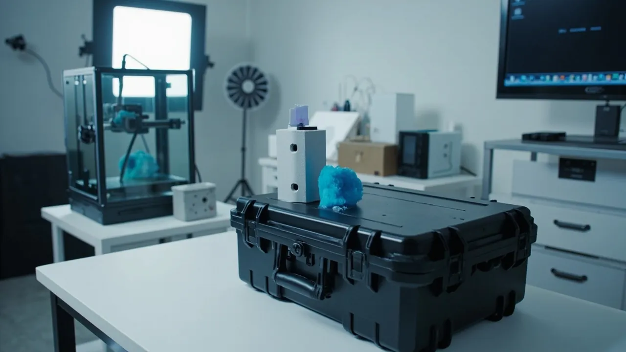
A 3D printer is a machine whose accuracy lives inside its structure: it does not protect precision with its enclosure, it maintains precision through frame stiffness, rail straightness, belt tension and leadscrew concentricity. That means transport damage is rarely a visible break - it is accuracy drift: a slightly twisted gantry, a few micrometres of bow in a linear shaft, a change in belt tension, a small angular error at a coupler. The machine still powers on, still homes, still "prints", but first-layer adhesion degrades, XY dimensional error grows, and Z layers show banding or layer shifts. For industrial users, this hidden damage is harder to diagnose than a dented housing and considerably more expensive.
This article is written for 3D printer brands, additive manufacturing distributors, industrial users and education or research procurement teams. It breaks transport protection for fused deposition modelling (FDM) machines, large industrial printers and resin (SLA, DLP, LCD) systems into actionable engineering items: how frames and baseplates deform, straightness requirements for rails, shafts and leadscrews, motion system and belt tension control, the fragile points of extruders and hot ends, transport posture and posture locking, vibration G-level design, moisture, dust and residue handling, custom insert design for long parts, sealing to IEC 60529 and GB/T 4208, pressure equalization, ISTA and GB/T 4857 transport testing, and the receiving inspection flow including re-levelling and first-layer testing. All figures are typical industry values and empirical ranges; confirm against physical validation and the manufacturer's transport requirements.
Contents
- 1. Why a 3D printer needs a dedicated transport case
- 2. Machine types and vulnerability decomposition
- 3. Frame and baseplate: how deformation actually happens
- 4. Rails, shafts and leadscrews: straightness determines accuracy
- 5. Motion system and belt tension control
- 6. Protecting the extruder, hot end and heated bed
- 7. Transport posture and posture locking
- 8. Vibration design: G levels and long cantilever structures
- 9. Moisture, dust and residue handling
- 10. Custom inserts: long-part support and locating design
- 11. Sealing, IP ratings and pressure equalization
- 12. Transport testing and receiving inspection
- 13. Compliance, marking and safety boundaries
- 14. Selection checklist, cost and OEM/ODM collaboration
- Frequently Asked Questions (FAQ)
- Conclusion and Related Reading
1. Why a 3D printer needs a dedicated transport case
The sales and delivery chain for a 3D printer is long: factory to master distributor, master distributor to dealer, dealer to end user, with LTL freight, parcel sorting, forklift handling and repeated manual lifts in between, plus 30 to 45 days of sea freight on export orders. Each transfer exposes the machine to random vibration and drop shock, and its accuracy class typically sits in the 0.05 to 0.2 mm range, making it highly sensitive to structural displacement.
One underrated fact: the transport ruggedness of a 3D printer depends not on its enclosure but on the slenderness ratio of its internal structure. A 220 x 220 x 250 mm desktop machine has a near-cubic frame and is relatively robust. A 500 x 500 x 500 mm industrial machine has an X-axis beam and Z leadscrews that behave as long cantilevers or slender members, where vibration can produce deflections of several tenths of a millimetre - enough to push first-layer height outside tolerance.
Typical transport scenarios and risks:
| Transport scenario | Dominant load | Typical risk | Protection focus |
|---|---|---|---|
| --- | --- | --- | --- |
| Factory to dealer (LTL) | Repeated sorting drops of 60 to 90 cm | Frame corner deformation, screen cracking, bed glass fracture | Reinforced corners, full-unit locating, soft facing on screen |
| Dealer to user (parcel or truck) | 5 to 200 Hz random vibration | Rail bowing, belt tension change, cable abrasion | Long-part support, posture locking |
| Export sea freight (25 to 45 days) | High humidity, salt spray, day-night temperature swings | Board moisture, rail corrosion, resin residue leakage | Barrier packaging, desiccant, drained resin vat |
| Trade show and lab-to-lab moves | One-sided lifting, case tumbling | Gantry twist, coupler misalignment | Two-person handling design, casters plus handle |
| Long-term storage | Static stacking load, humidity cycling | Insert compression set, belt relaxation | Stack load design, moisture control, periodic maintenance |
Three signals that a dedicated case is justified: print volume larger than 300 mm or positioning accuracy better than 0.1 mm; a route that includes sea freight, multimodal transfer or more than two handling points; or a machine that must return to the factory for repair or travel the trade show circuit. Any one condition is normally enough for the case to pay back within six to twelve months through fewer accuracy-related returns and faster delivery. If the shipment also includes optically calibrated items such as machine vision cameras and lenses, which many industrial machines integrate for monitoring, the protection level must rise again.
2. Machine types and vulnerability decomposition
Structures differ enormously between 3D printing technologies, and so do the vulnerabilities. Decompose the structure before designing any insert.
| Machine type | Typical mass | Critical vulnerable points | Insert contact strategy |
|---|---|---|---|
| --- | --- | --- | --- |
| Desktop FDM (i3 gantry) | 6 to 15 kg | Gantry uprights, Z shafts, heated bed glass, screen | Support both gantry uprights, full support under the bed |
| Desktop FDM (CoreXY or cross-axis) | 8 to 20 kg | XY belts, linear rails, tool head, frame corners | Load at frame corners, lock tool head at its park position |
| Industrial FDM (large format) | 40 to 300 kg | Long beams, dual Z leadscrews, platform, sheet-metal base | Multi-point multi-layer base support, independent pressure bars on beams |
| Resin (SLA, DLP, LCD) | 10 to 60 kg | Resin vat, release film, LCD screen, Z leadscrew, build plate | Vat must be drained and packed separately, clearance above screen |
| Powder bed (SLS) | Above 100 kg | Rails, recoater roller, thermal elements | Treat as powder equipment, separate cavities |
| Accessories (spools, nozzles, tools) | 0.5 to 10 kg | Nozzle bore, thermistor wiring, spool deformation | Separate small cavity, nozzle protection cap |
Three hard rules:
- Long parts need multiple support points. Beams, shafts, leadscrews and glass platforms are slender structures; supporting only the two ends leaves maximum deflection in the middle. Use two to four support points across the span, with soft contact faces.
- Moving parts must be locked at their park position. If the tool head, bed or spool holder can move freely in transit, they will repeatedly strike end stops or rail ends under vibration, causing deformation and motor load spikes. Lock the tool head in the position the manufacturer specifies, usually with a transport lock or strap points.
- Never change the transport posture. The manufacturer normally specifies it - upright for most machines, a specific orientation for some large models - because Z leadscrews and gantry structures are orientation sensitive. Changing posture introduces additional bending moments, as discussed below.
Other equipment in the same "accuracy held by structure" category includes measuring instruments covered in the instrument case selection guide, where the insert design logic is very similar: decompose vulnerabilities first, then discuss materials.
3. Frame and baseplate: how deformation actually happens
The frame is the skeleton of a 3D printer, and its deformation propagates into every motion axis. There are three common frame constructions:
| Frame construction | Stiffness | Deformation-sensitive areas | Transport concern |
|---|---|---|---|
| --- | --- | --- | --- |
| Aluminium extrusion plus corner brackets | Medium | Bracket joints, long member mid-span | Align insert support blocks with the brackets |
| Folded sheet-metal base plus uprights | Medium to low | Fold lines, baseplate flatness | Multi-point base support, no unsupported spans |
| Cast or welded monolithic frame | High | Machined interface faces | Full-unit locating, prevent twisting |
| Resin machine body (base plus Z column) | Medium | Column perpendicularity, base levelness | Support column at both top and bottom |
Three main sources of deformation:
- Static bending from self-weight. If the case is tilted in transit, long beams and uprights experience bending moments in directions they were never designed for; prolonged tilt can cause plastic deformation.
- Cyclic stress from vibration. Random vibration from 5 to 200 Hz keeps the frame under alternating load; bracket screws can gradually loosen, and once loose the frame loses stiffness, creating a feedback loop where more movement loosens screws further.
- Impact load from drops. In a corner drop, shock travels through the case and insert into the frame; if the insert supports only from below with no lateral restraint, the machine tumbles inside the cavity and takes concentrated impacts at its corners.
Structural countermeasures:
- Load at the corners. Place insert support points at frame corner brackets and base reinforcement zones, not on thin outer panels. Thin panels dent under load, damaging appearance and potentially pressing into internal parts.
- Anti-twist locating. Add locating blocks on the diagonal of the frame so the machine cannot rotate about the vertical axis and drive a long edge into the insert.
- Screw torque verification. Check the torque of frame bracket and rail mounting screws before shipping and record it; sample-check on arrival as one indicator of whether the shipment exceeded limits.
For enclosure material and overall structure selection, see plastic protective case construction and case seal material selection.
4. Rails, shafts and leadscrews: straightness determines accuracy
This is the most critical and most frequently overlooked section of 3D printer transport protection. Straightness error in rails and leadscrews shows up in the printed part at roughly one-to-one, or even amplified.
| Component | Typical accuracy requirement | Transport risk | Protection requirement |
|---|---|---|---|
| --- | --- | --- | --- |
| Linear rail (ball type) | Straightness 0.01 to 0.05 mm per 300 mm | Brinelling of the carriage under side load, rail bowing | Multi-point support along length, no side loading |
| Round shaft | Straightness 0.05 to 0.2 mm per 500 mm | Bending that does not recover, XY dimensional error | Support across the full span, never hang loads on it |
| Ball screw | Lead error in the tens of micrometres | Bending that produces periodic Z banding | Support at both ends plus mid-span, no axial shock |
| Timing belt | Tension stability | Tension change causes dimensional error and ringing | Set to manufacturer's tension before shipment, re-check on arrival |
| Coupler | High concentricity requirement | Angular error after shock, Z axis judder | Avoid axial shock, never lift the machine by the uprights |
Four key insights:
- Straightness damage is irreversible. Once a shaft or leadscrew has plastically bowed, re-levelling cannot restore it; the part must be replaced. The protection goal is therefore not "reduce damage" but "stay within the elastic limit".
- Rails tolerate axial load, not side load. Ball carriage load capacity is directional; a side impact presses the balls into the raceway, leaving Brinelling marks that produce a notchy feel and accuracy fluctuation. The insert must provide soft lateral restraint so the machine cannot swing sideways.
- Mid-span deflection of long parts is the real danger. A 500 mm shaft supported only at its ends can sag tens of micrometres under its own weight when horizontal, and vibration amplifies that in transit. Where possible, orient long parts in their stiffest direction - usually vertical for rails - or support them continuously.
- Check straightness on arrival. Industrial users should have a dial indicator plus V-blocks or a dedicated fixture ready and sample-check the critical axes; desktop users should at minimum do a full-travel hand-feel check and a first-layer test.
Concrete packaging measures:
- Place two to four V-shaped or U-shaped soft cradles along the rail span, faced with EVA or polyurethane, so no hard plastic contacts the rail surface.
- Add locating ribs on both sides of the rail with 1 to 2 mm clearance per side and soft contact on the pressure bar.
- Never place spools, tool boxes or other heavy items on top of a beam or rail.
5. Motion system and belt tension control
The motion system of an FDM machine consists of stepper motors, timing belts, idlers and tensioners. Belt tension is a parameter that is "set at the factory, disturbed in transit, and must be re-checked".
How transport affects the motion system:
| Effect | Mechanism | Symptom on arrival | Action |
|---|---|---|---|
| --- | --- | --- | --- |
| Belt tension loss | Idler or tensioner creeps under vibration | Ringing at corners, dimensional error | Re-measure and re-tension |
| Belt tracking drift | Side impact on idler bearing | Running noise, edge wear | Inspect idler mount for deformation |
| Stepper losing position | Tool head forced to move in transit | Homing faults | Dry-run test and re-home |
| Cable chain wear | Cables rubbing inside the chain | Damaged cable jacket, intermittent open circuit | Visual inspection of chain and cables |
| Bearing lubrication loss | Heat or prolonged tilted storage | Increased running noise | Re-grease per maintenance schedule |
Three insert design requirements:
- Lock the tool head at its park position. Most FDM printers have X and Y park positions or accept a transport lock. Use the manufacturer's lock if supplied; if not, add a soft pressure bar that gently holds the tool head at park.
- Restrain the heated bed. Spring steel or glass beds can lift or slide in transit; add a retaining lip on the insert so the bed cannot strike the gantry or the nozzle.
- Do not compress the cable chain. The chain is a wear item; never clamp it with the insert. Cut a relief channel around it instead.
Tension re-check. On arrival, re-measure belt tension to the manufacturer's recommendation - some vendors specify a sonic tension gauge method, others allow an approximate pluck-frequency method. For industrial buyers ordering in volume, put "belt tension re-check" on the acceptance checklist, because this single item drives corner accuracy and surface finish.
General cushioning and locating practice is covered in cushion liner case design and sealed shock-resistant case structure.
6. Protecting the extruder, hot end and heated bed
The extruder and hot end are among the most fragile, most expensive and cheapest-to-protect parts of a 3D printer, and also the most likely to be struck in transit.
| Component | Vulnerable point | Common transport damage | Protection measure |
|---|---|---|---|
| --- | --- | --- | --- |
| Nozzle | Bore diameter and end face | Bent tip, debris blocking the bore | Fit a protection cap, nozzle facing inward |
| Heater block and cartridge | Wiring and terminals | Broken wire root, loosened terminal | Secure the wiring separately, never tug it |
| Thermistor or thermocouple | Extremely thin lead wires | Broken lead (shows as a temperature error) | Coil and fix the lead, avoid tension |
| Fan and heat break | Blades, cooling fins | Deformed blades, bent fins | Cut relief around them |
| Glass bed | Flatness | Glass fracture, chipped edges | Soft liner above, locating on all four sides |
| PEI or spring steel sheet | Coating | Coating scratches | Non-woven or soft film on the surface |
| Resin vat and release film | Film tension | Film rupture, resin leakage | Drain resin, pack the vat separately |
Three practical points:
- The hot end is a precision assembly - remove and pack it separately where possible. On industrial machines, remove the whole hot end assembly (nozzle, heater block and heat break) and pack it in a dedicated cavity box. If removal is impractical, at minimum fit a nozzle cap and secure the wiring.
- Glass parts need soft support above and below plus side locating. Glass is brittle and point-load sensitive. Provide soft liner both above and below and use locating blocks to restrain horizontal movement, so the glass cannot slide and strike metal parts during a drop.
- Resin machines must be drained before shipment. Residual resin seeps along gaps in transit, contaminating the screen, rails and electronics, and some resin components are irritants to skin and respiratory tract. Drain, clean the vat and plate with the manufacturer's recommended cleaner, let them dry, then pack; transport resin bottles separately in a light-blocking package.
On consumables storage. Protecting the printer and protecting its consumables are two separate problems: filament is moisture sensitive and resin is sensitive to both light and moisture, requiring dedicated humidity-controlled, light-blocking storage with silica gel and UV-cure material handling rules. That is a different design problem and is not covered here, but note that you should never pack filament spools in the same case as the printer - spools press on the frame under vibration and are more likely to absorb moisture.
7. Transport posture and posture locking
This is the most commonly mishandled and most consequential section of 3D printer transport. A printer is not a machine that "can be shipped any way up".
How posture matters:
- Z leadscrew and coupler. The leadscrew primarily carries axial load in service. If the machine is laid on its side or inverted, the screw carries a radial bending moment, and for a slender screw with a high length-to-diameter ratio this can cause plastic bowing, producing periodic Z banding.
- Gantry uprights. The upright-to-base joint is designed for an upright machine; laying it down subjects the joint to combined shear and bending.
- Bed and platform. When laid on its side, the platform weight forms a cantilever through its mounting points and can deform the platform bracket.
- Liquid and powder residue. If resin, grease or powder remains inside, changing posture sends it to places it should never reach.
Four posture management rules:
- Follow the manufacturer's transport requirement. Most vendors state "upright transport only, no inversion or side placement", and some large models specify a particular face up. Obtain the requirement in writing at the procurement stage.
- Mark orientation on all four sides of the case. Apply "this way up" arrows plus "do not invert or lay on side" icons, and state "contains precision rails - do not tilt beyond XX degrees".
- Design the insert for the specified posture only. Do not design an insert that claims to work in any orientation; multi-orientation compatibility leaves every direction under-supported and is more dangerous overall.
- Limit the tilt angle. For large machines, state a tilt limit in the markings (an empirical value often quoted is no more than 30 degrees, but follow the manufacturer). Ask the carrier to use air-ride or air-suspension vehicles to reduce road shock and rollover risk.
How to implement it in the insert: in the specified posture, place load-bearing points under the base reinforcement zones and frame corner brackets; add soft lateral restraints at 2 to 3 mm clearance on the sides and a light compression layer on top, giving a three-sided constraint of "base carries load, sides locate, top lightly presses". For very heavy machines, add independent straps and metal fittings, but never run a strap directly across a rail or cable.
8. Vibration design: G levels and long cantilever structures
Vibration protection for a 3D printer must balance overall machine mass against long cantilever behaviour.
| Item | Typical requirement or empirical value | Notes |
|---|---|---|
| --- | --- | --- |
| Allowable peak acceleration (whole machine) | Empirical target 25 to 50 g | Scales with mass; heavier machines tolerate more |
| Drop height by total mass | Under 10 kg: 76 to 90 cm; 10 to 20 kg: 60 to 76 cm; 20 to 40 kg: 45 to 60 cm; above 40 kg: per vendor and contract | Following ISTA and GB/T 4857 logic |
| Cushion layer thickness | 25 to 60 mm per side | Increase for long cantilever structures |
| Insert static compression | 15 to 30 percent | Too soft bottoms out, too hard transmits |
| Packaging system natural frequency | Must avoid the 10 to 200 Hz excitation band | Tune by thickness and density |
| Number of drops | 6 to 10 impacts across corners, edges and faces | Corner drops are the most severe |
Two special problems with long cantilever structures:
- Local amplification at the tip. The free end of a long beam or upright can see higher acceleration than the machine average, so those locations need independent supports or pressure bars rather than relying on whole-unit locating.
- Insert stiffness distribution. If the insert has uniform hardness, the contact pressure on a heavy machine concentrates at a few points. A practical approach is gradient support: higher-density EVA (60 to 90 kg/m3) in heavily loaded zones and lower density (38 to 50 kg/m3) in lightly loaded zones.
| Cushion material | Density (kg/m3) | Rebound behaviour | Under sustained vibration | Best position |
|---|---|---|---|---|
| --- | --- | --- | --- | --- |
| EVA (moulded or CNC-cut) | 38 to 90 | Fast rebound, good set | Low compression set | Preferred for custom inserts |
| PE foam | 25 to 45 | Slow rebound, soft | Collapses after repeated drops | Low-cost secondary cushion |
| EPP (expanded polypropylene) | 30 to 60 | Excellent rebound | Strongest against repeated impact | Base filling for heavy machines |
| Polyurethane (PU) | 20 to 60 | Soft and conforming | Moderate fatigue resistance | Conforming layer for rails and odd shapes |
A practical verification method: place pressure-sensitive or carbon-copy paper at the insert load points, load the machine, simulate one corner drop, then unload and inspect the impression pattern. A few deep spots mean uneven support; a broad shallow pattern means the design is sound. This low-cost check is very effective at the prototype stage.
9. Moisture, dust and residue handling
Moisture. Motherboards, stepper driver boards and connectors are all moisture sensitive, and 30 to 45 days at sea can cause surface leakage on boards and corrosion on rails. Control is layered:
- Barrier layer. Heat-sealed aluminium foil laminate with water vapour transmission around 0.1 g/(m2 per 24 h); ordinary PE bags are often above 5 g/(m2 per 24 h).
- Absorption layer. Silica gel sized against free air volume; for a target below 40 percent RH, use 30 to 60 g per 30 litres, taking the upper end for sea freight.
- Indication layer. Humidity indicator card or electronic logger for arrival assessment.
Rails and leadscrews should be coated with anti-corrosion grease before shipment, and sulphur- or chlorine-containing materials should be avoided inside the package because they can promote metal corrosion.
Dust. Dust contaminates the rail lubricating film and accelerates wear, most noticeably on powder bed machines. Avoid shedding liner materials; never let unsealed corrugated board or textile fabric touch the machine directly.
Residue handling, a frequently missed step:
| Machine type | Pre-shipment action | Reason |
|---|---|---|
| --- | --- | --- |
| FDM | Clear debris and filament remnants, remove spools | Prevents remnants jamming the motion system |
| Resin | Drain the vat, clean and dry the plate and vat | Prevents leakage onto electronics and the screen |
| Powder bed | Clear unmelted powder, seal the powder chamber | Dust leakage and explosion risk, requiring dangerous-goods compliance |
| All types | Clean rails and re-grease, inspect cable jackets | Reduces corrosion and wear |
Cleaning and maintenance. On arrival, dust the machine and clean the rails before running the levelling procedure. Cleaning and care for the case itself is covered in protective case cleaning and maintenance; for machines going into long-term storage see protective case service life and maintenance.
10. Custom inserts: long-part support and locating design
Insert design for 3D printers has a distinctive long-part character: support across long spans while leaving clearance for moving components.
Six-step process:
- CAD or physical capture. Prefer the vendor STEP model; otherwise 3D scan and model with 3 to 5 mm allowance for tool head position, cabling and cable chain.
- Vulnerability marking. Mark no-compression zones (bed glass, screen, resin vat, fan intakes), must-support zones (long beams, shafts, base reinforcement) and must-locate zones (frame corners, diagonal directions).
- Layer structure. Common stack is base support plus locating layer plus compression layer, 60 to 160 mm total; heavy machines get a double base with gradient density.
- Finger clearance and assembly tolerance. Finger notches 25 to 35 mm wide and 20 to 30 mm deep; 1 to 2 mm clearance per side against soft liner, plus 3 to 5 mm relief for long parts.
- CNC carving or mould sampling. CNC for small batches, moulding for large ones. Laminated inserts may be glued or mechanically joined, but adhesive layers must not touch rails or optical parts.
- Physical fit validation. After loading, perform a full case rotation at 1 m within the manufacturer's permitted posture range plus lift tests, confirming no displacement, no insert tearing and no evidence of side loading on rails.
| Insert process | Suitable batch size | Unit cost | Revision flexibility | Consistency | Notes |
|---|---|---|---|---|---|
| --- | --- | --- | --- | --- | --- |
| CNC-carved EVA | 1 to 500 | Medium | Very high | Medium | First choice for sampling, no tooling |
| Compression-moulded EVA | Above 1000 | Low | Low | High | Requires aluminium or steel tool |
| Multi-layer laminated | Any | Medium-high | High | Medium | Suits deep cavities and long-part zoning |
| Removable divider system | Any | Medium | High | Medium | Helps cover several machine models |
Three long-part support techniques:
- V-shaped soft cradle. For shafts and leadscrews; face it with soft material and keep contact width at least 10 mm to avoid line contact.
- Independent pressure bar. For long beams; at least 15 mm wide, soft contact, limiting inertial displacement without applying preload.
- Removable dividers. If one case must accommodate several machine models, a removable divider system can resize cavities, but each model still needs individual validation; see case removable divider system.
On 3D printing projects, JUNZHJIA typically develops inserts from customer CAD models or scanned physical units, supports both CNC-carved and moulded EVA routes, matches gaskets and latches to the case size, and can provide dimensional reports and drop validation records. If you are comparing insert options, start with the custom foam inserts guide and the EVA foam insert custom process.
11. Sealing, IP ratings and pressure equalization
IEC 60529, mirrored nationally in China by GB/T 4208, is the international basis for enclosure protection ratings, coded IPXY: the first digit covers solid particles and dust (0 to 6), the second covers water (0 to 9K).
| Rating | Dust | Water meaning | Fit for 3D printer scenarios |
|---|---|---|---|
| --- | --- | --- | --- |
| IP54 | 5 | Splash from any direction, no harmful effect | Indoor handling |
| IP65 | 6 (dust tight) | 6.3 mm nozzle jet from any direction | Rainy docks, brief outdoor exposure |
| IP66 | 6 | 12.5 mm nozzle, powerful jets | Washdown environments |
| IP67 | 6 | Temporary immersion, 1 m for 30 minutes | Sea freight, flooding risk |
| IP68 | 6 | Immersion conditions agreed between supplier and buyer | Requires explicit parameters |
| IP69K | 6 | High-temperature, high-pressure jet | Food and cleaning industries |
Three misconceptions to correct:
- IP67 and IP68 are not equivalent. IP68 immersion depth and duration are not fixed and must be agreed.
- Dust and water are tested separately. Passing IP6X does not imply passing IPX7.
- Seal performance decays over time. EPDM and silicone gaskets age under ultraviolet, ozone, oils and repeated compression; replacement is usually assessed at three to five years.
Why the pressure equalization valve is necessary. Above IP65 the internal air is sealed in, so temperature change converts directly into a pressure differential. With 30 litres of free air and a 70 K swing, the theoretical differential reaches the order of 20 kPa. The consequences include difficult opening, the gasket being pumped out of its groove, and moisture being repeatedly drawn in so the desiccant is exhausted quickly. The solution is a pressure equalization (breather) valve, whose core is a hydrophobic, oleophobic ePTFE microporous membrane: gas passes slowly, liquid water and dust do not.
| Parameter | Suggested value or concern | Notes |
|---|---|---|
| --- | --- | --- |
| Air flow rate | Matched to case volume | Large cases need a higher-flow valve or two valves |
| Opening and closing differential | Lower is more responsive | Typically a few kPa |
| Water protection contribution | Valve body itself should exceed IP67 | Otherwise it becomes the weakest point |
| Membrane temperature range | -40 to +125 degrees C common | Covers sea and air freight |
| Mounting position | High on a sidewall, out of direct water impact | Also keep clear of the equipment |
Note that a sealed case without a breather valve has usually lost its IP67 claim after one inter-climatic shipment. See case pressure equalization valve design and waterproof case IP implementation. Hinge, latch and gasket cooperation is detailed in case hinge, latch and seal structure.
12. Transport testing and receiving inspection
Protection capability must be demonstrated by test. At minimum, procurement should specify which standard, which items and to what level.
| Standard | Nature | Content | Meaning for 3D printer cases |
|---|---|---|---|
| --- | --- | --- | --- |
| ISTA Series 1 | Non-simulation performance test | Drop, vibration, compression basics | Basic screening for new designs |
| ISTA Series 2 | Partial simulation | Drop plus vibration plus compression | Common for single-parcel shipment |
| ISTA Series 3 | General simulation | Tailored to package format and route | Closest to cross-border courier and multimodal |
| GB/T 4857 series | National transport package tests | Stacking, vibration, impact, drop as separate items | Common for domestic projects and customer acceptance |
| ASTM D4169 | Distribution cycle performance test | Test sequence per distribution cycle | When full distribution-cycle evidence is required |
| MIL-STD-810H | Environmental test methods | Vibration, shock and temperature-humidity methodology | Borrow quantitative methods and levels; not a military certification |
| IEC 60068-2-52 | Salt spray test | Corrosion environment validation | Sea freight and coastal scenarios |
| IEC 60529 / GB/T 4208 | Enclosure protection | IP test methods and criteria | Shared language for sealing performance |
Wording on MIL-STD-810H must be rigorous. It is a set of environmental test methods; a manufacturer may reference its methods (for example Method 514 vibration, Method 516 shock) to structure a validation programme, but referencing a method does not confer military certification or equipment qualification. External documents should state "tested following MIL-STD-810H methods; not a military certification". See MIL-STD-810H compliance interpretation.
A recommended staged validation path:
- Design freeze (sample case). Loaded corner, edge and face drops at heights set by mass, plus 1 to 2 hours of random vibration and 24 hours of static stacking; afterwards inspect for cracks, gasket displacement and insert compression set.
- Design validation. Full ISTA 3A or ASTM D4169 sequence, focused on whether the machine inside still meets its factory accuracy specification.
- Production. First-article confirmation plus sampling of key dimensions and gasket hardness under an AQL plan.
Receiving inspection checklist, especially important for 3D printers:
| Inspection item | Method | Acceptance reference |
|---|---|---|
| --- | --- | --- |
| Frame and rail straightness | Dial indicator with V-blocks or a dedicated fixture | Compare with factory records; exceeding vendor tolerance is abnormal |
| Belt tension | Sonic tension gauge or vendor-specified method | Per vendor recommendation |
| Screw torque | Torque wrench, sampling frame brackets and rail screws | Consistent with factory records |
| Motion feel | Full-travel hand push and pull on each axis | No notchiness, no abnormal noise |
| Homing and end stops | Home each axis in sequence | No fault codes |
| Levelling and first layer | Run the levelling routine and print a first-layer test | Uniform first layer with normal adhesion |
| Dimensional accuracy | Print a standard test artefact and measure | Consistent with factory accuracy |
| Electrical and thermal | Heaters, temperature sensing, fans, screen | No temperature faults, no broken wiring |
Conclusion: for a 3D printer, "the case survived" is not the acceptance criterion - "the accuracy is unchanged" is. Put this table into the receiving acceptance clause of the purchase contract and require the supplier to provide test-related records. Test details are covered in ISTA transport testing procedures, GB/T 4857 transport packaging testing and ASTM D4169 distribution cycle testing.
13. Compliance, marking and safety boundaries
3D printers are generally not dangerous goods, but four boundaries must be stated clearly:
- Machines containing lithium batteries. Some printers include a UPS module or wireless module; if a lithium-ion pack is fitted, the package may fall under UN38.3 and lithium battery transport rules with packing instruction and state-of-charge requirements. Road ADR, sea IMDG and air IATA differ substantially and must be confirmed per mode; see hazmat-compliant transport cases.
- Resin and powder residue. Some photopolymer resin components irritate skin and respiratory tract, so the vat must be drained and cleaned before shipment. Metal powder is a combustible dust with explosion risk and must be strictly sealed under the applicable regulations. Powder equipment transport should be assessed separately rather than assuming the generic approach in this article applies.
- Wood packaging and ISPM 15. Wooden pallets or crates used for export reinforcement must meet ISPM 15 heat treatment or fumigation with the appropriate mark; a reusable plastic case normally avoids that step.
- Material compliance. EU exports require attention to RoHS and REACH, covering the case, the insert and labelling adhesives. Ask for material declarations in the contract.
Suggested marking list: case model and serial number, IP rating, stack limit, gross weight and external dimensions, machine name and quantity, up arrows plus do-not-invert and do-not-lay-on-side icons, and the tilt angle limit, keep-dry icon, desiccant replacement date, and the notice "contains precision rails - do not tilt or throw". For resin machines, also mark "resin drained and cleaned" so it can be verified on arrival.
14. Selection checklist, cost and OEM/ODM collaboration
Compressing the technical items into a scoring matrix you can take into negotiations substantially reduces the risk of choosing by feel.
| Scoring dimension | Suggested weight | What to assess | Typical deductions |
|---|---|---|---|
| --- | --- | --- | --- |
| Insert-to-machine fit | 25 percent | Vulnerability decomposition, long-part multi-point support, posture locking, finger notches | Generic pick-and-pluck foam |
| Long-part and posture protection | 15 percent | V-shaped cradles, independent pressure bars, diagonal anti-twist locating | Base support only |
| Sealing and IP performance | 15 percent | IP67 with itemised test records, gasket material | "Waterproof" with no data |
| Shock and cushioning design | 15 percent | Gradient material density, thickness, G-level target, drop validation | Wall thickness quoted without insert design |
| Structure and durability | 10 percent | Hinges, latches, wall thickness, stack load | Plastic hinges, thin walls |
| Ergonomics and marking | 10 percent | Handles, casters, label areas, orientation icons | No handle, no orientation marking |
| Compliance documentation | 6 percent | UL94, RoHS/REACH, test reports | Missing or delayed documents |
| Delivery and after-sales | 4 percent | Lead time, spare parts such as gaskets and inserts | Spares not sold separately |
Cost and delivery:
| Cost item | Drivers | Reduction levers |
|---|---|---|
| --- | --- | --- |
| Case tooling | Size, structural complexity, cavity count | Use a standard case size plus custom insert |
| Insert processing | Process (CNC or moulded), layers, material density | Move to moulding at higher volumes |
| Test validation | Number of test items, number of samples | Screen with a single case before full validation |
| Packaging accessories | Desiccant, indicator cards, seals, labels | Standardise procurement |
| Logistics | External dimensions and stacking efficiency | Optimise outline to raise container fill rate |
Lead time is usually set by three things: insert sampling and approval (often the longest), tooling fabrication, and test scheduling. For large-format 3D printers the case itself may also need tooling, so run all three workstreams in parallel.
OEM/ODM collaboration points: clarify ownership and confidentiality for insert models and case drawings; agree the scope of inspection documents (first-article dimension report, material declaration including UL94 and RoHS/REACH, seal performance and drop test records); confirm that gaskets, inserts, latches and casters can be ordered separately; and confirm peak-season capacity and minimum order quantity. For large cases, caster and handle load design is critical - see case wheels and trolley handle design and case lock customisation options.
JUNZHJIA, manufactured by Kexin New Materials (Guangdong) Co., Ltd., supplies wholesale, distribution and OEM/ODM customers, and can build inserts, posture locking components and seal sets matched to specific FDM and resin printer models, along with custom screen printing, orientation markings and seal schemes. For tooling economics see custom case mould cost analysis, for batch acceptance sampling see custom case AQL acceptance, and for supplier evaluation see how to choose a case OEM factory.
Frequently Asked Questions (FAQ)
Q: Can I just put a 3D printer in a big box with some foam? A: For a toy-grade desktop machine it is barely acceptable; for a machine with 0.1 mm class accuracy it is high risk. The reason is that a 3D printer's accuracy is maintained by slender structures - shafts, leadscrews and long beams - whose straightness error appears directly in the printed part. These structures do not fail because the housing was struck; they fail under side loading and mid-span deflection. A generic foam box cushions only from below, provides no multi-point support for long members, and cannot stop the machine rotating about its vertical axis inside the case; a single LTL shipment with several sorting drops can bow a rail irreversibly. Unlocked tool heads and beds also hammer their end stops under vibration. As a practical rule, any machine with a print volume above 300 mm, positioning accuracy better than 0.1 mm, or a route including sea freight or multimodal transfer, should use a dedicated case with long-part supports and posture locking, with accuracy re-check written into the acceptance clause.
Q: Can a 3D printer be shipped on its side or upside down? A: In principle no, and most vendors explicitly state "upright transport only". Z leadscrews, couplers and gantry uprights are designed for an upright machine. Laying the machine down subjects a slender leadscrew to a radial bending moment that can cause plastic bowing and periodic Z banding; the upright-to-base joint sees combined shear and bending that can loosen brackets or deform the interface; and the bed weight forms a cantilever through its mounts and can deform the platform bracket. If resin or grease remains inside, a posture change sends it toward the screen, rails or electronics. Follow the manufacturer's written transport requirement, mark up arrows and do-not-invert icons on all four sides of the case, state a tilt limit (an empirical value often quoted is no more than 30 degrees, but follow the vendor), and design the insert for the specified posture only.
Q: Does the machine need re-levelling after transport, and will accuracy recover by itself? A: It needs re-levelling, and not all deviations recover on their own. Small deformations within the elastic range may relax once the load is removed, but three classes do not: plastic bowing of shafts and leadscrews, Brinelling marks in ball rails, and permanent loss of belt tension. A sensible arrival sequence is: visual and cable inspection; full-travel hand push and pull on each axis to feel for notchiness or noise; re-measure belt tension and re-tension to the vendor value; run the levelling routine and print a first-layer test; then print a standard test artefact and measure XY and Z dimensions. Industrial users should additionally sample-check critical axis straightness with a dial indicator against factory records. If the first layer is uniform and dimensional accuracy matches the factory figure, transport can be judged not to have caused material harm; a regular pattern of first-layer deviation usually points to a rail or leadscrew problem.
Q: Should the hot end and extruder be removed and packed separately? A: Industrial machines should remove them; desktop machines should at minimum fit a nozzle cap and secure the wiring. The hot end assembly has many fragile points. A nozzle bore is only 0.2 to 0.8 mm, and even a light knock on the end face affects extrusion. The wire root on a heater block breaks easily after repeated flexing, showing up as a heating fault. Thermistor and thermocouple leads are extremely thin and break if put under tension, showing as temperature errors or jumps. Fan blades and heat break fins also bend under pressure. The safe approach is to remove the whole hot end assembly and pack it in a dedicated cavity box with a machined channel that locates it by shape; if it stays fitted, cap the nozzle, coil and secure the leads without tension, and cut relief in the insert around the fan and heat break fins. Check temperature stability and heating function on arrival.
Q: Must a resin 3D printer be drained before transport? A: Yes. Residual resin seeps along gaps in transit and contaminates the machine internals: on the LCD it can fog the screen or cure into a blockage, on the Z leadscrew and rails it captures dust and accelerates wear, and on electronics and connectors it causes leakage or poor contact. Most photopolymer resins also irritate skin and respiratory tract in their uncured state, so a leak is a safety issue for handlers. The correct flow is to drain the vat (the resin can be filtered and returned to its bottle), clean the vat and build plate with the vendor's recommended cleaner, dry them thoroughly, and then pack; transport resin bottles separately in a light-blocking package. Mark the case "resin drained and cleaned" so the receiver can verify. If cleaning cannot be done at the shipping site, state in the contract which party is responsible, to avoid disputes on arrival.
Q: Why does a sealed case need a pressure equalization valve? A: Because sealing and temperature change are in unavoidable conflict. Packaging temperature and in-transit temperature can differ by 40 to 70 K, so enclosed air expands when warm and contracts when cold, producing differentials from several kPa to tens of kPa. There are four consequences: the lid may spring open or be very hard to open, creating an injury risk; the gasket is pumped out of its groove and takes a permanent set; each pressure cycle exchanges a small volume of gas, continuously pumping moisture in and exhausting the desiccant; and inside a barrier bag, the differential presses the film against the machine and may rupture it. A pressure equalization valve uses a hydrophobic and oleophobic microporous membrane so gas passes slowly while liquid water and dust cannot, removing the differential without sacrificing the IP rating. Confirm that the valve body itself reaches IP67 or better, that flow matches case volume, and that it is mounted high on a sidewall away from direct water impact.
Q: Should the insert be EVA or PE, and what structure should long-part supports use? A: For a reusable 3D printer case, EVA is usually better: low compression set, stable rebound, easy to carve precisely and to conform, with surface resistivity tunable through formulation. PE foam is cheaper and softer, suitable for a secondary cushion layer or short-trip handling, but collapses after repeated drops. EPP has the strongest repeated-impact performance and suits base filling in heavy machines, though it is difficult to machine into fine locating features. PU conforms well for odd shapes such as rails, but absorbs moisture more readily, so it needs care on long sea voyages. For long-part support, combine three structures: V-shaped soft cradles for shafts and leadscrews with contact width of at least 10 mm to avoid line contact; independent soft pressure bars for long beams, limiting inertial displacement without applying preload; and two to four support points across the span instead of supporting only the ends, which leaves maximum deflection in the middle. Heavy machines benefit from gradient density: 60 to 90 kg/m3 in loaded zones and 38 to 50 kg/m3 in lighter zones.
Q: What tests should a 3D printer case undergo, and what should acceptance cover? A: Three stages are recommended. At design freeze, perform loaded corner, edge and face drops with heights set by total mass (commonly 76 to 90 cm below 10 kg, 60 to 76 cm for 10 to 20 kg, and 45 to 60 cm for 20 to 40 kg), followed by 1 to 2 hours of random vibration and 24 hours of static stacking; afterwards inspect for cracks, gasket displacement and insert compression set. At design validation, run the full ISTA 3A or ASTM D4169 sequence and focus on whether the machine still meets its factory accuracy. In production, combine first-article confirmation with sampling of key dimensions and gasket hardness. Acceptance must include an accuracy re-check clause: frame and rail straightness, belt tension, screw torque, motion feel, homing, levelling and first layer, and dimensional accuracy on a test artefact. For a 3D printer, "the case survived" is not the acceptance criterion - "the accuracy is unchanged" is. If a customer requires MIL-STD-810H, its vibration and shock methods may be followed, but documentation must state that it is not a military certification.
Conclusion and Related Reading
The core proposition in 3D printer transport protection is that accuracy is maintained by structure, and structure is vulnerable to posture and deflection. Unlike ordinary industrial equipment, the risk rarely shows up as a broken enclosure; it shows up as accuracy drift with no obvious cause. Effective solutions follow one logic: support and locate the slender structures properly - rails, leadscrews, beams, glass platforms - lock moving parts at their park positions, control transport posture strictly as the manufacturer requires, and then prove by drop and vibration testing that the machine inside still meets its factory accuracy.
For engineers and buyers, the most useful test is this: the value of a transport case is not that the case is intact, but that the first layer prints correctly straight out of the box. Start the insert, posture locking, sealing and moisture control, testing and receiving inspection workstreams in parallel at project kickoff, and attach the inspection checklist to the contract. That reduces repair and commissioning costs and creates a repeatable standard process for volume deliveries and trade show circuits.
Related Reading