

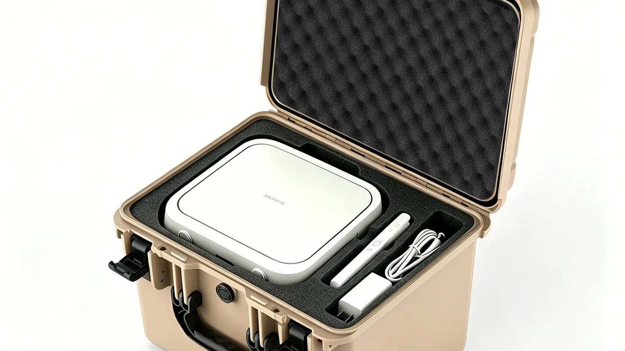
Six exhibitions a year, three cities, two ocean freight legs: that is the standard annual rhythm for many brands that tour their display hardware. The moments that actually damage exhibits rarely happen under the spotlights. They happen at the factory loading bay, in the line-haul trailer, on the convention center dock, at the freight elevator, and during the hurried repack in the forty minutes after the hall closes. A single three-stop tour exposes one case to a dozen full-case handlings, two long hauls, and six or more open-and-close cycles. Add one ocean or air leg and the shell also absorbs the heat and humidity of a sealed container plus the random impacts of a cargo terminal belt. JUNZHIJIA designs trade show cases as reusable logistics units rather than disposable packing consumables: verifiable structures, quantifiable cushioning and traceable identification turn every uncertainty on the touring route into a controlled variable inside one box.
The cost of failure is what separates a trade show case from an ordinary tote. When an ordinary tote breaks, you lose a tote. When a trade show case fails two hours before doors open, you lose the entire presentation, on top of booth rental and contractor labor already paid. The correct objective is therefore not the lightest shell or the lowest unit price, but determinism across a defined number of tours: every opening delivers intact exhibits. This article works through the touring scenario end to end, from the failure spectrum and quantified duty cycle to shell process, sealing, cushioning, cavity layout, hardware, handling ergonomics, asset control, climate response, test validation and the custom build path.
Table of Contents
- Failure Spectrum of Trade Show Cases: Six Damage Modes on the Touring Route
- Quantifying the Touring Duty Cycle: Handling Counts, Drop Heights and Vibration Spectra
- Shell Materials and Processes: Rotomolded PE, Injection PP and Aluminum Honeycomb Compared
- Sealing and Dust Protection: What IP65 and IP67 Really Buy You at a Venue
- Cushion Liner Design: EPE, EVA and IXPE Cavities with Bearing Stress Checks
- Cavity Layout for Exhibits: Odd Shapes, Lightbox Panels and Fragile Inserts
- Latches, Hinges and Stacking: High-Frequency Opening and Palletized Transport
- Wheels, Handles and Handling Ergonomics: The Airport to Aisle Chain
- Labels, Packing Documents and Touring Asset Control: The Case as a Logistics Unit
- Climate and Salt Fog: Coastal Venues, Ocean Freight and High Humidity
- Transport Testing and Acceptance Criteria: Applying ISTA, ASTM D4169 and GB-T 4857
- Selection Checklist and Custom Build Path: From Exhibit List to Production Tooling
- Frequently Asked Questions FAQ
- Conclusion and Related Reading
Failure Spectrum of Trade Show Cases: Six Damage Modes on the Touring Route
The load spectrum a touring case sees has little in common with a warehouse tote. It must survive random vibration on the highway, rough manual handling on the show floor, a fast repack at closing, and still deliver pristine exhibits at the next venue. Broken down across the full route, failures fall into six families: shell cracking or puncture, corner wear and stack collapse, liner creep that lets exhibits migrate, seal failure admitting dust and water, latch and hinge fatigue, and lost identification causing misrouted or missing cases. These six are rarely independent. A corner drop produces slight flange distortion; the distorted flange reduces seal compression; dust enters on the next leg; the dust settles on a lightbox panel and degrades the very thing the case was built to protect.
| Failure mode | Primary trigger | Visible consequence | Design countermeasure |
|---|---|---|---|
| --- | --- | --- | --- |
| Shell crack or puncture | Corner drop, sharp point loading, low-temperature embrittlement | Exhibits exposed, case scrapped | Uniform rotomolded wall, generous radii, low-temperature resin grade |
| Corner wear, stack collapse | Multi-layer pallet stacking, sustained top load | Top case sinks, lid will not open | Interlocking stack bosses, side ribs, marked stack limit |
| Liner creep, exhibit migration | Repeated drops plus long-term static load | Rattle inside cavity, scuffed surfaces | Density selected by bearing stress, allowance for compression set |
| Seal failure, dust and water ingress | Flange distortion, aged gasket, insufficient latch force | Fixture short circuits, moisture damage | Lip or hollow-bulb gasket, latch count and clamping force check |
| Latch and hinge fatigue | High-frequency opening, side loading in transit | Lid opens during transport | Cycle-validated hardware, metal hinge pins, anti-release features |
| Lost label, wrong or missing case | Decal peels off, number abraded | Wrong exhibit on site, delayed opening | Laser marking, recessed nameplate, color-coded zoning |
The practical reading of this table is that a touring case cannot be engineered only for the single worst drop. Shell strength governs the one-off limit; liner and hardware govern long-term consistency; labeling and documentation govern whether a fleet of cases still makes sense after many rotations. Miss any one of the three and the touring route develops a hole.
Quantifying the Touring Duty Cycle: Handling Counts, Drop Heights and Vibration Spectra
Getting protection right starts not with material selection but with numbers everyone can argue about. A touring case design input should cover at least five items: handling count, drop height, vibration spectrum, stack layers and climate window. Handling count sets the fatigue requirement for latches and hinges. At twelve full-case handlings per year with two openings each, that is twenty-four cycles annually and roughly seventy-two over a three-year service life. If the case is also used for routine warehouse access, the real number is far higher, which is why latch and hinge validation should be specified at five thousand open-close cycles rather than at touring counts.
Drop height scales with the handling method. Single-person carry drops land around 0.8 to 1.0 m; two-person shoulder carry or a trolley tip-over reaches 1.0 to 1.2 m; a belt end or a forklift attachment release produces 0.5 to 1.5 m, most often onto an edge or a corner. Touring cases are typically large and loaded between 15 and 60 kg, placing them in the category of manually handled but near the limit, which makes the corner drop the governing check.
On vibration, highway line-haul energy concentrates between 3 and 100 Hz, rail between 2 and 80 Hz, and air cargo holds present broadband random input from 5 to 200 Hz plus landing shock. Overall levels are usually taken as 0.4 to 0.7 Grms. For large thin panels such as lightbox faces and acrylic sheets, low-frequency large-displacement flexing causes fatigue cracking far more often than high-frequency shock, a point routinely missed in specification work.
| Design input | Typical touring value | Basis | Design elements affected |
|---|---|---|---|
| --- | --- | --- | --- |
| Handlings per year | 12 to 24 | Show calendar plus warehouse access frequency | Latch and hinge fatigue class |
| Drop height | 0.8 to 1.5 m | Manual handling limit and belt drop | Shell wall thickness, liner thickness |
| Vibration Grms | 0.4 to 0.7 | Measured road, rail and air spectra | Liner dynamic stiffness, divider stiffness |
| Stack layers | 3 to 4 static, 2 dynamic | Warehouse and trailer practice | Top ribs, interlock geometry |
| Climate window | -10 C to 50 C, 10 to 95 percent RH | Cross-season touring and ocean legs | Resin grade, gasket compound |
| Loaded mass | 15 to 60 kg | Exhibit and accessory list | Handles, wheel set, trolley load rating |
Stacking and climate deserve the same rigor. Static storage in a warehouse or trailer may run three to four layers; dynamic transport should be held to two layers with stretch film and corner protection. The climate window is set at minus 10 C to 50 C with 10 to 95 percent relative humidity, and any ocean leg adds a sealed container condition near 60 C and 95 percent RH plus a salt-laden atmosphere.
Shell Materials and Processes: Rotomolded PE, Injection PP and Aluminum Honeycomb Compared
Choosing a shell process is really a trade between dimensional precision, impact resistance, tooling investment and perceived quality. Three routes dominate: rotomolded polyethylene, injection molded polypropylene, and aluminum extrusion or honeycomb composite construction.
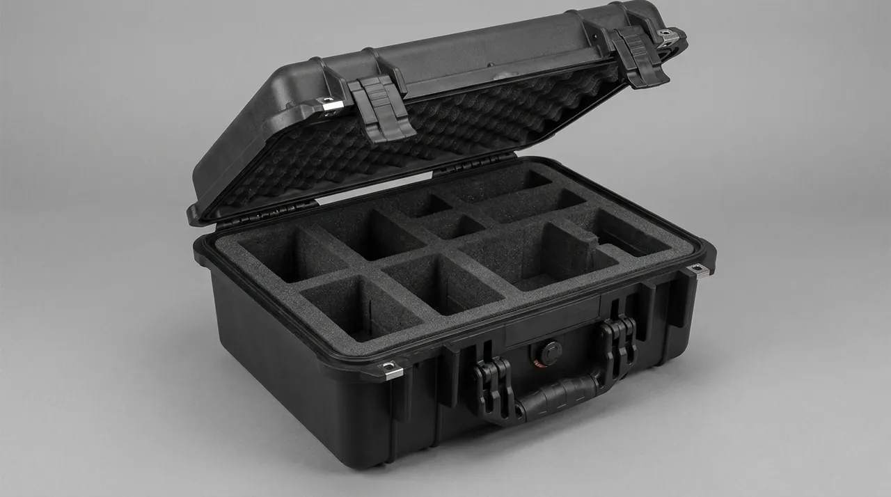
Rotomolding uses linear low-density polyethylene powder that fuses against a biaxially rotating heated mold. Wall thickness lands at 4 to 6 mm and is remarkably uniform, there are no weld lines, and corners come out as large radii, giving the best corner-drop performance of the three. Tooling runs only 15 to 30 percent of an equivalent injection tool, which suits large cases in volumes of hundreds to a few thousand, and the same tool readily integrates stack bosses, wheel bosses and molded-in inserts. The trade-offs are moderate dimensional accuracy, a matte orange-peel surface, and limited ability to form fine snap-fit features.
Injection molded polypropylene runs 2.5 to 3.5 mm wall, holds tight tolerances, accepts textured or polished surfaces, and supports complex ribs, snap fits, living hinges and raised lettering. It fits small to medium cases in the tens of thousands where appearance consistency matters. The penalty is very high tooling cost at large sizes, and weld lines become the mechanical weak points, so gate locations must be fixed during design and kept away from loaded corners. Cold-climate projects need copolymer or impact-modified grades to avoid embrittlement near minus 10 C. A systematic comparison is available in Rotomolded versus Injection Protective Cases.
Aluminum extrusion and honeycomb composite shells are extremely stiff, light, and visually premium, suiting image-critical display hardware and sample cases. Their weak points are corner joints and dent resistance: thin sheet takes permanent dents in a corner drop that spoil the appearance and cannot be repaired, while corner bracket and rivet or weld quality sets service life, and salt environments demand 304 or 316 stainless fasteners. Further material guidance is in Protective Case Plastic Materials and Aluminum Case Construction.
| Process | Typical wall | Dimensional accuracy | Corner drop resistance | Tooling cost | Appearance | Best fit |
|---|---|---|---|---|---|---|
| --- | --- | --- | --- | --- | --- | --- |
| Rotomolded PE | 4 to 6 mm | Medium | Excellent | Low | Medium | Large sizes, hundreds to thousands |
| Injection PP | 2.5 to 3.5 mm | High | Medium | High | High | Small sizes, tens of thousands |
| Aluminum honeycomb | 1 to 2 mm faces | High | Medium, dents easily | Medium | High | Image-critical and sample cases |
Sealing and Dust Protection: What IP65 and IP67 Really Buy You at a Venue
Sealing requirements at exhibition venues are routinely underestimated. During setup, crews cut timber, grind metal and lay carpet, so airborne particulate loads far exceed normal indoor levels. Outdoor pavilions and loading docks add wind-driven rain and splashing from standing water. For luminaires, power modules and display electronics, dust-induced contact failure and shorting is in practice more common than water damage. Under IEC 60529 and GB-T 4208, the first digit denotes solid ingress protection and the second water: IP6X is dust tight, IPX5 resists water jets, IPX6 resists powerful jets, IPX7 covers temporary immersion. IP65 is the mainstream touring target; IP66 or IP67 is warranted for open-air booths or deck cargo.
Sealing is a system property, not a component property. Gasket compounds are typically EPDM, silicone or thermoplastic elastomer at 50 to 70 Shore A. The governing properties are compression set and low-temperature recovery; measured to GB/T 7759 at 70 C for 22 hours, compression set should stay under 25 percent. Hollow-bulb or lip profiles maintain line contact across a slightly uneven flange far more tolerantly than solid sections.
Even the best gasket needs adequate clamping force and a flat flange. Latch count and spacing set how evenly that force distributes around the perimeter; place one near each corner and add points at 300 to 400 mm along long runs. Insufficient sidewall stiffness lets the shell bulge between latches and opens a visible gap. Pressure differentials from altitude or temperature are relieved through a Pressure Equalization Valve for Protective Cases, which also prevents hard-to-open lids and gasket damage. System-level thinking is covered in System Level IP67 Design and Outdoor Case Seal Ring Design.
Cushion Liner Design: EPE, EVA and IXPE Cavities with Bearing Stress Checks
A touring case liner is not foam stuffed into a box; it is a cushioning calculation. The governing parameters are the exhibit fragility level, expressed as the maximum permitted acceleration in G, the static stress carried by the pad, and the material cushion curve. Static stress equals exhibit weight divided by load-bearing projected area; the cushion curve for that material returns the resulting peak acceleration. The design target is a peak acceleration below the fragility level.
Representative fragility levels: glass lightbox panels and large acrylic sheets sit around 30 to 50 G, LED modules and drivers 40 to 60 G, precision instruments 20 to 30 G, and timber samples or metal parts 80 to 120 G. Drop height comes from the quantified duty cycle above. Pad thickness follows from the compression stroke required, initially sized so peak strain at maximum drop height stays below 70 percent, then corrected against the cushion curve.
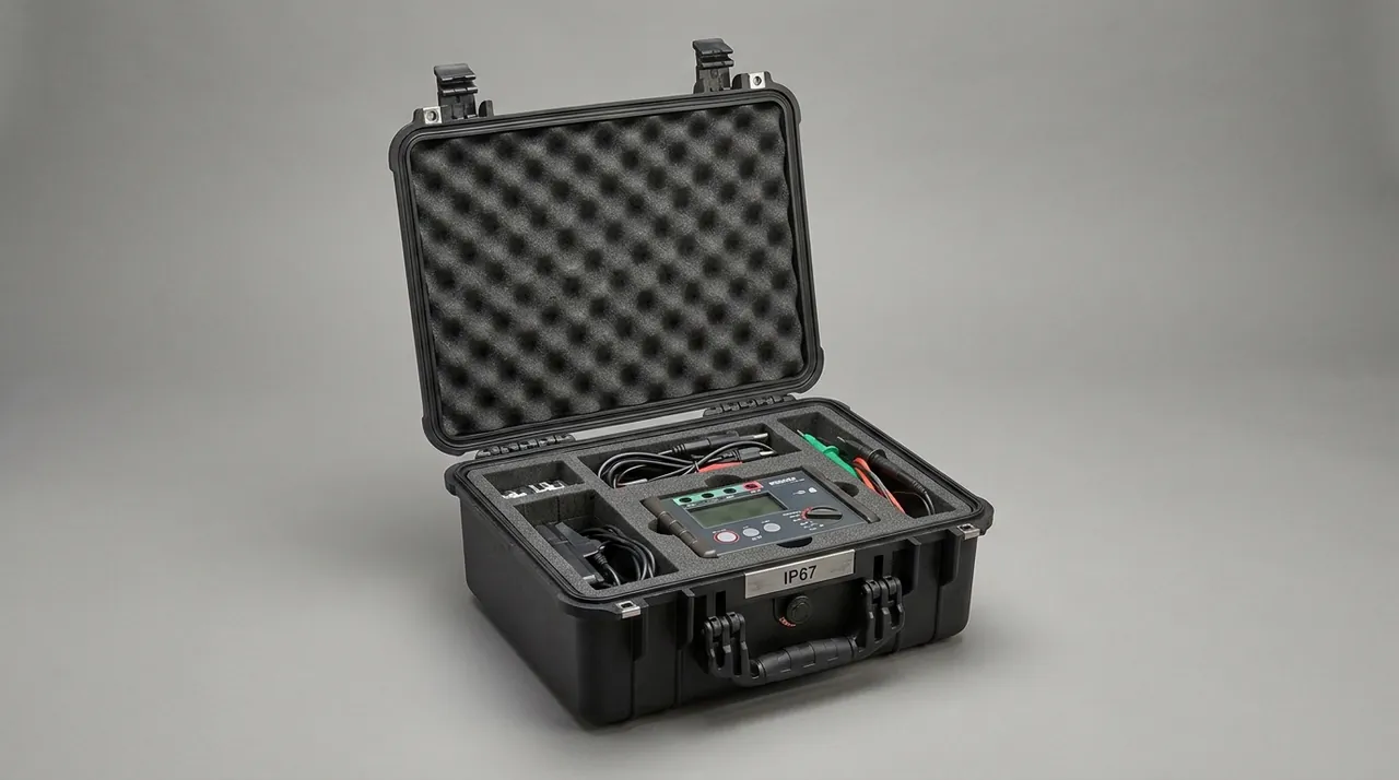
Material trade-offs are set out in EPE versus EVA Foam Toolbox Liners. EPE at 20 to 30 kg per cubic meter rebounds well, costs least and does not absorb water, suiting moderate bearing stress and use as a base pad. EVA at 60 to 120 kg per cubic meter thermoforms cleanly and cuts to a dense, non-shedding edge, making it the primary formed-liner material. IXPE at 30 to 60 kg per cubic meter has a fine closed cell structure, a smooth surface and excellent repeated-compression behavior, ideal against high-gloss exhibit faces. PU foam conforms beautifully but absorbs moisture and loses rebound faster under sustained load. The formed-liner workflow is described in EVA Foam Insert Custom Process, with broader context in Cushion Liner Protective Cases.
One more quantity is routinely ignored: accumulated creep. After sustained static load and repeated drops, foam loses 5 to 15 percent of its thickness, the liner loosens, and exhibits begin to micro-shift inside the cavity. Custom liners should therefore be built with 0.5 to 1.0 mm of interference compression around each exhibit, and validation should confirm retention after thirty drops rather than only in the as-new condition.
| Material | Density, kg per cubic meter | Useful static stress, kPa | Rebound | Shedding | Relative cost |
|---|---|---|---|---|---|
| --- | --- | --- | --- | --- | --- |
| EPE | 20 to 30 | 3 to 12 | Excellent | Low | Low |
| EVA | 60 to 120 | 10 to 30 | Good | Very low | Medium |
| IXPE | 30 to 60 | 5 to 18 | Excellent | Very low | Medium high |
| PU foam | 30 to 80 | 2 to 8 | Moderate | Low | Medium |
Cavity Layout for Exhibits: Odd Shapes, Lightbox Panels and Fragile Inserts
Exhibit sets are stubbornly irregular: slender aluminum extrusions, large thin lightbox panels, power boxes trailing cables, display samples of every geometry. The first rule of cavity layout is one exhibit per cavity, with no exhibit-to-exhibit contact. The second is a centered and low center of gravity so the loaded case does not roll during handling. The third is that removal order must follow setup order, with the first items needed sitting in the top layer.
Panels belong upright, not flat. Laid flat, a large thin sheet flexes repeatedly under random vibration, leading to fatigue cracking or chipped edges, and in a stack the lowest sheet carries the full weight of everything above while the contact faces scuff each other, which is fatal for gloss surfaces. Upright slotted storage turns gravity into an in-plane load, removing bending stress, and separates every sheet. Size the slot at panel thickness plus 1 to 2 mm, with depth no less than one fifth of panel width, and line the slot walls with IXPE or felt. Glass and high-gloss acrylic should not lie against foam over a large area for long periods, because heat and humidity leave pressure marks; the correct approach is to float the display face and locate the panel only by its edges.
Odd-shaped samples go into routed or thermoformed cavities with contact area held between 30 and 60 percent of total surface: less concentrates stress, more removes cushioning stroke. Cables, screws and clamps get bagged and placed in a dedicated accessory cavity so nothing loose can scratch a primary exhibit. Choosing between adjustable dividers and a fixed formed liner is covered in Removable Divider Systems for Cases and Pick and Pluck Foam Case Liners; when the exhibit list changes often, dividers win on flexibility, while a fixed list of high-value items favors formed liners, a trade analyzed in Dividers versus Foam Inserts.
Latches, Hinges and Stacking: High-Frequency Opening and Palletized Transport
Touring hardware faces high cycle counts and high abuse simultaneously. Draw-type latches are simple, inexpensive and one-hand operable, making them the touring default. Butterfly latches deliver high clamping force and accept padlocks, suiting heavy or pilferage-sensitive cases. Concealed push latches look clean for brand-critical builds but are harder to service. Opening force should fall between 40 and 80 N: higher fatigues crews across a setup day, lower risks vibration release in transit.
Hinge selection follows lid opening angle and load path. A full-length piano hinge spreads load across the entire case width and resists distortion best, the right choice above roughly 800 mm of hinge line; split hinges are easier to replace but leave shell regions between hinges prone to local twist in a drop. Specify 304 stainless pins, with nylon or polyoxymethylene bushings to cut squeak, and move to 316 for coastal or ocean service. A full hardware treatment is in Toolbox Hinge, Latch and Seal Construction.
Stacking is what separates a touring case from a generic one. Interlocking bosses on the lid engaging recesses in the base restrict relative sliding both in the warehouse and on the road, while vertical side ribs carry top load straight down to the base instead of letting walls bulge. On a 1200 by 1000 mm pallet, four cases per layer is typical, with two layers in dynamic transport and three to four in static storage, plus a clearly marked layer limit on the shell. Verification methods appear in Stackable Toolbox Design Benefits and Toolbox Durability and Load Testing.
Wheels, Handles and Handling Ergonomics: The Airport to Aisle Chain
A touring case normally travels in three segments: trailer to venue dock, dock to booth via ramp or freight elevator, and final positioning inside the booth. Wheels carry the first, wheels plus a trolley handle the second, and grab handles the third. Omitting any one of the three pushes crews into dragging and rolling the case on its edge, which does far more damage than any wheel boss ever will.
Wheel selection turns on diameter, tread compound and bearing. Diameters of 100 to 125 mm clear floor joints, carpet seams and small thresholds far better than anything under 80 mm. Polyurethane or thermoplastic elastomer treads at 80 to 90 Shore A balance rolling resistance against noise, and noise matters: hard nylon wheels are shrill on stone concourses. Sealed precision ball bearings keep setup dust out and prevent seizing. Wheels should be a replaceable module, because they are the fastest-wearing part of any touring case and a replaceable design converts end-of-life from "wheels failed" to "swap the wheels."
Handle geometry follows human scale. Specify a two or three stage telescoping handle adjustable between 900 and 1050 mm of grip height, and size the wheel-to-grip lever arm so the case trails at 30 to 45 degrees; steeper angles load the wrist unnecessarily. Provide at least one side handle and one end handle, and use recessed hidden grips to avoid snagging in stacks and trailers. Where cases travel with staff or cover long concourses, see Industries for Trolley Toolboxes and Travel Case Construction Essentials.
Labels, Packing Documents and Touring Asset Control: The Case as a Logistics Unit
Once a tour involves a dozen or more cases, management difficulty exceeds protection difficulty. Treating each case as a numbered, traceable logistics unit is the cheapest available way to cut show-day risk.
Use a three-part numbering scheme of project code, stop sequence and case sequence, so that P24-S2-07 reads as project 24, stop two, case seven. Give every case at the same stop the same color decal and change color between stops so loaders can sort at a glance. Put the number on the shell rather than only on a sticker: laser marking, a recessed nameplate or screen printing survive, whereas printed labels are usually gone after three tours. Fix a sealed document pouch inside holding the packing list, exhibit photographs and an assembly diagram, and repack against those photographs at closing to cut missing parts sharply.
External markings matter as much. Apply the fragile, this-way-up, stacking limit and keep-dry symbols per GB-T 191 on multiple faces, not one, so at least one is visible in any orientation. QR codes or RFID tags enable batch scanning at dispatch and receipt and tie the touring asset register to the physical case. For brand presentation, screen printing, film decals and aluminum nameplates each have their place, with options covered in Protective Case Color Customization and Plastic Functional Box Marking Design.
Climate and Salt Fog: Coastal Venues, Ocean Freight and High Humidity
The harshest leg of a tour is often environmental rather than mechanical. A shipping container in direct sun exceeds 60 C internally at near-saturation humidity, and the day-night cycle produces container rain that pours onto cases the moment doors open. Coastal venues add continuous salt deposition that attacks metalwork.
Metal protection combines material upgrade with surface treatment. Latches, hinges, pins and screws should be 304 stainless as a baseline, moving to 316 for ocean or coastal programs; where budget constrains, use Dacromet or zinc-nickel plating validated by neutral salt spray to GB/T 10125 with no red rust at 48 to 96 hours. Dissimilar metal contact drives galvanic corrosion, so aluminum shells with stainless fasteners need insulating washers or coatings.
Plastics need protection against ultraviolet and thermal-oxidative aging. Polypropylene and polyethylene undergo chain scission under UV, showing as fading, chalking and embrittlement, countered through masterbatch and hindered amine light stabilizer packages and evaluated by 200 to 400 hours of QUV accelerated weathering for color shift and retained tensile strength. Gaskets in humid service must resist mold, where silicone and EPDM outperform natural rubber. Shell design for wet and hot extremes is covered in Outdoor Rain and Humidity Case Design, Outdoor Case Temperature Extremes and Outdoor Case High Altitude Performance.
Transport Testing and Acceptance Criteria: Applying ISTA, ASTM D4169 and GB-T 4857
Protection claims on a touring case have to be settled by test. Internationally the references are ISTA 3 series and ASTM D4169; in China the equivalents are the GB/T 4857 family, with GB/T 4857.5 for drop, GB/T 4857.3 for stacking, GB/T 4857.7 and 4857.10 for vibration, and GB/T 4857.2 for conditioning. For selection, ISTA 3A suits single parcels under 70 kg moving by parcel or less-than-truckload, ISTA 3E suits unitized pallet loads, and ASTM D4169 allows custom severity by distribution cycle, which fits intercontinental touring.
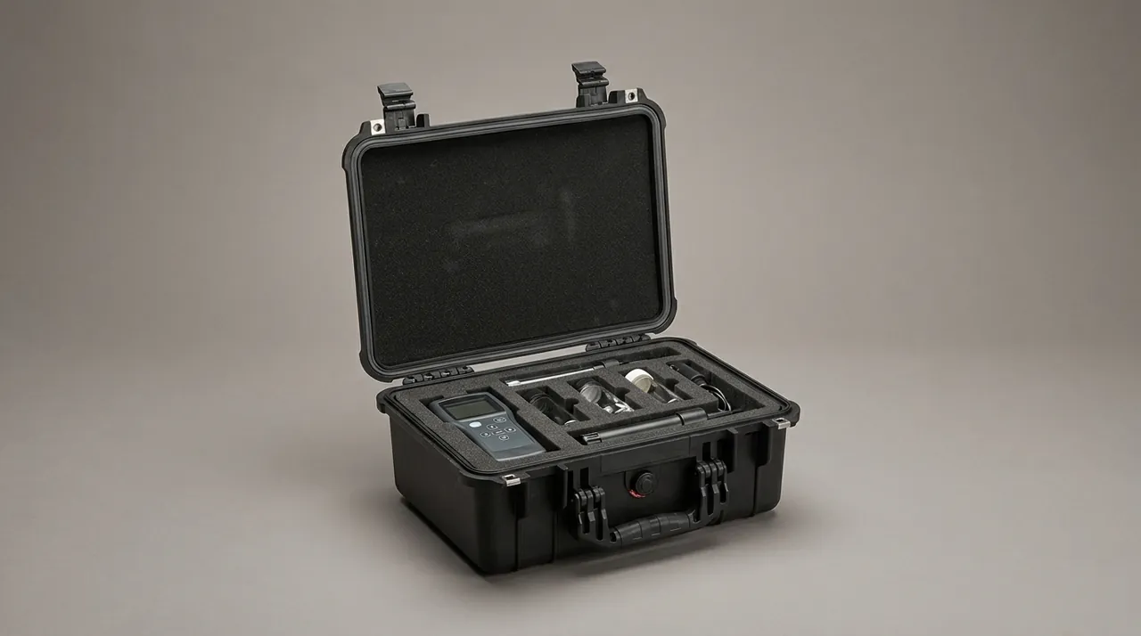
Drop testing runs one corner, three edges and six faces, with height graded by loaded mass: 0.8 m from 10 to 20 kg, 0.6 m from 20 to 30 kg, 0.5 m from 30 to 40 kg, and lower still for heavier cases with attention concentrated on edges and corners. Random vibration follows a measured or standard spectrum at 0.4 to 0.7 Grms overall for 60 to 180 minutes per axis, run on all three axes where the program justifies it. Stacking applies 1.4 times the actual stacked load for 24 hours.
| Test item | Reference method | Typical parameters | Pass criteria |
|---|---|---|---|
| --- | --- | --- | --- |
| Drop | GB/T 4857.5, ISTA 3A | One corner, three edges, six faces, 0.5 to 1.0 m | No through crack, lid stays closed |
| Random vibration | GB/T 4857.7, ASTM D4169 | 0.4 to 0.7 Grms, 60 to 180 min | Liner set 10 percent or less, exhibit functional |
| Stacking | GB/T 4857.3 | 1.4 times actual load, 24 h | Top residual deflection 3 mm or less, lid opens |
| Dust and water | GB-T 4208, IEC 60529 | IP65 or IP67 | No visible dust or water inside |
| Conditioning | GB/T 4857.2 | 40 C, 90 percent RH, 48 h | No softening, no gasket debonding |
| Salt spray | GB/T 10125 | NSS 48 to 96 h | No red rust on metal parts |
Acceptance criteria must be written as decidable clauses, never as "appearance acceptable." Specify that the shell shows no through crack and no crack longer than 50 mm; that post-seal-test interiors show no visible dust or water; that permanent liner set stays within 10 percent of original thickness; that every latch opens normally with clamping force loss under 15 percent; and that all exhibits pass functional checks. Lot sampling is addressed in Custom Case Acceptance and AQL, and immersion procedure detail in IP67 Submersion Test Method.
Selection Checklist and Custom Build Path: From Exhibit List to Production Tooling
Pulling every element together, a touring case program runs in twelve steps. First, compile an exhibit list with dimensions, weight, fragility and quantity for every item. Second, fix internal clear dimensions and the cavity plan. Third, choose the shell process from loaded mass and tours per year. Fourth, set the ingress rating and sealing approach. Fifth, make a first pass at liner material and thickness. Sixth, produce 3D models and prototype. Seventh, run drop and vibration validation. Eighth, correct liner and structure from results. Ninth, fix color, markings and case documents. Tenth, cut production tooling or build fixtures. Eleventh, run a pilot batch and recheck. Twelfth, deliver volume and archive documentation.
On schedule, programs built on an existing shell platform with a new liner are fastest, prototyping in two to three weeks. A new rotomolding tool typically takes four to eight weeks, which with prototyping and correction puts the program at six to twelve weeks; large injection tools take longer. Add one to two weeks where full transport testing and ingress validation are required. In practice, start custom work at least twelve weeks before the show, especially for first-time suppliers or ocean programs, and freeze the exhibit list early, because liner design depends entirely on exhibit dimensions and a changing list is the single most common cause of schedule slips.
Frequently Asked Questions FAQ
Q: Should a trade show case use rotomolding or injection molding?
A: The decision turns on three variables: size, volume and appearance expectations. When the longest side exceeds 800 mm, loaded mass runs above 30 kg, and volume sits between a few hundred and a few thousand units, rotomolded polyethylene is almost the only economical answer. Wall thickness lands at 4 to 6 mm and distributes evenly, there are no weld lines, and corners form naturally as large radii, giving the best corner-drop resistance of any route, while tooling costs only 15 to 30 percent of an equivalent injection tool. Below roughly 600 mm, at volumes in the tens of thousands, and where textured or polished surfaces plus complex snap fits and living hinges are needed, injection polypropylene wins. A third route, aluminum extrusion or honeycomb composite, is stiff, light and visually premium, but thin sheet dents permanently in a corner drop and its joints need 316 stainless fasteners in salt air. Always weight tour frequency too: above six tours a year, put impact resistance ahead of cosmetics.
Q: Is IP65 enough for a trade show case, and when is IP67 required?
A: For indoor halls and covered loading docks, IP65 covers nearly every realistic risk. The first digit 6 means dust tight, which blocks the airborne particles generated when crews cut timber and grind metal during setup, and the second digit 5 means protection against water jets, which handles rain at the dock and splashing from wet floors. Three situations justify moving to IP66 or IP67: booths in open-air or semi-covered pavilions where cases may sit in rain for hours, transport legs involving deck cargo or open port storage, and payloads such as high-value display panels or precision instruments where even minor ingress is unaffordable. Note that IP67 describes temporary immersion under a defined depth and duration; it is not a license for prolonged submersion and it does not substitute for drop and vibration validation. Achieving the higher rating requires coordinated work across gasket section, latch clamping force, flange flatness and pressure equalization, not simply a different seal strip. Where cases travel by air, specify an equalization valve alongside the rating so the lid does not bind at altitude.
Q: Should lightbox panels and acrylic sheets be stored flat or upright?
A: Upright, without exception. Flat storage has two clear faults. First, a large thin sheet flexes repeatedly under random vibration, which over a tour produces fatigue cracking or chipped edges. Second, in a stack the bottom sheet carries the entire weight of everything above it, and the contacting faces scuff against each other under vibration, which is effectively fatal for gloss finishes. Upright slotted storage converts gravity into an in-plane load, removing bending stress, and separates each sheet so nothing touches. Size the slot at panel thickness plus 1 to 2 mm, with depth at least one fifth of panel width, and line slot walls with IXPE or felt. For glass and mirror-finish acrylic, also avoid pressing the display face against foam across a large area for extended periods, since heat and humidity leave pressure marks; float the face and locate the panel by its edges only. Where a panel is too large to stand, the fallback is flat storage with interleaved separators and strict control of stack height.
Q: Foam liners loosen over time; how can that be delayed?
A: Loosening is compression set and creep, meaning the material cannot fully recover its original thickness after sustained load and repeated impacts. Four layers of mitigation exist. The first is correct density and material: compute static stress from exhibit weight and projected area, then pick a density placing the operating point near the bottom of the cushion curve rather than at its edge, remembering that EVA and IXPE resist creep better than low-density EPE or PU foam. The second is interference allowance: build 0.5 to 1.0 mm of compression interference around each exhibit so the liner still grips after losing some thickness. The third is validating the aged condition rather than the new one, checking retention after thirty drops or equivalent vibration instead of only as-new. The fourth is usage discipline: avoid long-term fully loaded stacking, avoid leaving cases in hot vehicles, and place rather than throw cases during repack. Applied together, these typically give three to five years of effective liner life at normal touring intensity.
Q: Do touring cases need wheels and a trolley handle, and does that weaken the shell?
A: Yes to both questions: fit them, and done correctly they do not weaken the shell. A touring case travels from trailer across a dock, up a ramp or freight elevator, and down a hall aisle, and without wheels crews resort to dragging or rolling the case on its edge, which causes far more damage than any wheel boss opening. Strength comes down to how the wheel boss is engineered. Mount bosses where base ribs intersect or on dedicated molded-in inserts so load transfers through ribbing rather than through a few self-tapping screws into flat panel, and make the wheel module replaceable, since wheels wear fastest of any component and a swap-out design extends case life from wheels-failed to replace-the-wheels. Wider treads also help, spreading load on soft hall carpet and reducing sink at thresholds and cable ramps. For the handle, keep grip height adjustable between 900 and 1050 mm and trail the case at 30 to 45 degrees; a steeper angle puts needless bending load on the operator wrist and increases the chance the case is dropped.
Q: What extra preparation does an ocean freight leg require?
A: Ocean adds three risks that road transport does not. The first is heat, humidity and condensation: a sealed container in sunlight exceeds 60 C at near-saturation humidity, and the day-night cycle produces container rain that wets cases the moment doors open. Fit desiccant and moisture barrier bags, specify IP65 or better on the shell, and ventilate cases promptly on return. The second is salt corrosion: upgrade metal parts to 316 stainless or apply Dacromet or zinc-nickel coatings validated by 48 to 96 hours of neutral salt spray to GB/T 10125, and fit insulating washers wherever aluminum contacts stainless to prevent galvanic attack. The third is handling shock: port lifting gear and yard forklift attachments deliver far more energy than manual handling, so corners and stack interlocks must be checked against a harsher drop height, with stack layers strictly limited and stretch film plus corner boards applied. Container bracing matters too: strap or dunnage cases so they cannot shift with vessel motion, because a loose case accumulates damage across a multi-week voyage.
Q: How do I verify that a batch of trade show cases meets the design, and how should sampling be set?
A: Verification runs in two tiers. Type testing addresses the design and follows the GB/T 4857 family or ISTA 3A and ASTM D4169, covering drop, random vibration, stacking, conditioning and ingress, with criteria written as decidable clauses: no through crack or crack longer than 50 mm, no visible interior dust or water after seal testing, permanent liner set within 10 percent of original thickness, latch clamping force loss under 15 percent, and all exhibits passing functional checks. Delivery inspection addresses the batch under GB/T 2828.1. Appearance and dimensions typically use general inspection level II with an acceptance quality limit of 2.5, while critical items such as sealing and function use a tighter limit of 1.0 or a zero-defect rule. Retain test reports and retain samples from every lot so any dispute can be settled by retest rather than argument. Also define the failure response in advance: one critical defect under a zero-defect plan should trigger full screening of the lot plus containment of the root cause, not a second sample.
Q: How long does a custom trade show case program take from brief to delivery?
A: Timing depends on whether new tooling is required and whether full validation is included, which gives roughly three bands. Programs built on an existing shell platform with only a redesigned liner are fastest, prototyping in two to three weeks and delivering volume two to four weeks after approval; this suits tight show dates or late exhibit-list changes. Programs needing a new rotomolding tool run four to eight weeks for tool design and manufacture, plus prototype and correction, putting the total at six to twelve weeks; large injection tools take longer still. Add one to two weeks wherever full transport testing and ingress validation are in scope. As a working rule, start custom work at least twelve weeks before the show, particularly for first-time suppliers or ocean programs, and freeze the exhibit list as early as possible, because liner design depends entirely on exhibit dimensions and a list that keeps moving is the most common reason programs slip.
Conclusion and Related Reading
A touring case proves its worth only when it delivers undamaged exhibits after a dozen handlings, two long hauls and one night of rain. JUNZHIJIA provides custom liner design, tooling, OEM and ODM service for touring cases.
Related Reading